SNBC BTP-R880NPI User manual

Receipt Printer
BTP-R880NPII
SERVICE MANUAL

BTP-R880NPII Service Manual
- 1 -
Revision Sheet
Date
Version
Description
Distributor
2014-3-7
V1.0
Primary version

BTP-R880NPII Service Manual
- 1 -
Declaration
Information in this document is subject to change without notice. SHANDONG NEW BEIYANG
INFORMATION TECHNOLOGY CO., LTD. (hereinafter referred to as “SNBC”) reserves the right to
improve products as new technology, components, software, and firmware become available. If users need
further data about this product or have any doubt about safety issues that might arise from using it, please
feel free to contact SNBC or your local agents.
No part of this document may be reproduced or transmitted in any form or by any means, electronic or
mechanical, for any purpose without the express written permission of SNBC.
Copyright
Copyright© 2014 by SNBC
Printed in China
Version 1.0
Trademarks
Our registered trademarks are
Warnings and Cautions
Warning: Items shall be strictly followed to avoid damages to body and equipment.
Caution: Items with important information and prompts for operating the printer.
Certifications
The control system of SNBC has been approved of the following certifications:
ISO9001 quality control system certification
ISO14001 environmental control system certification
OHSAS18001 occupational health and safety control system certification
IECQ QC080000 hazardous substance process control system certification
Technical Contact Information
Address: No.169 Huoju Road High-tech Zone, Weihai, China
Hot line: 400-618-1368 800-860-1368
Fax: +86-631-5656098
PC: 264209
Website: www.newbeiyang.com.cn

BTP-R880NPII Service Manual
- 2 -
Notes
1) Follow the steps in this manual hereafter during maintenance.
2) Make sure that the printer and the computer are turned off before plugging the communication cable,
changing print head or doing maintenance to the printer.
3) Be sure to protect it against electrostatic damage when maintaining print head and other electronics.
4) Time between turning on and turning off the printer is no less than 20 seconds.
5) Do not operate the printer when paper is end. Doing so can damage print head.

BTP-R880NPII Service Manual
- 3 -
Content
DECLARATION.......................................................................................................................................................................1
1 FEATURE..............................................................................................................................................................................1
1.1 OUTLINE……………………………………………………………………………………………………………….1
1.2 MAIN FEATURE……………………………………………………………………………………………………….. 1
1.3 TECHNICAL SPECIFICATIONS………………………………………………………………………………………….2
1.4 POWER SWITCH,FEED BUTTON AND INDICATOR…………………………………………………………………….2
1.4.1 Power switch ........................................................................................................................................................2
1.4.2 Feed button...........................................................................................................................................................2
1.4.3LED Indicator.........................................................................................................................................................3
2 PRINTER OVERVIEW AND MODULES.........................................................................................................................4
2.1 PRINTER OVERVIEW………………………………………………………………………………………………….. 4
2.2 MAIN CONTROL BOARD UNIT BLOCK DIAGRAM…………………………………………………………………….. 5
3 COMMUNICATION INTERFACE......................................................................................................................................6
3.1 RS232 SERIAL INTERFACE…………………………………………………………………………………………… 6
3.1.1 Connector and specification ..............................................................................................................................6
3.1.2 Signal definition....................................................................................................................................................6
3.1.3 Interface parameters...........................................................................................................................................6
3.1.4 Default Setting......................................................................................................................................................6
3.1.5 Timing sequence..................................................................................................................................................7
3.1.6 Error processing...................................................................................................................................................7
3.2 USB INTERFACE……………………………………………………………………………………………………… 7
3.2.1 USB Interface Connector and Specifications..................................................................................................7
3.2.2 Signal Define of the USB Interface Module.....................................................................................................7
3.2.3 Signal cable of USB interface module .............................................................................................................8
3.2.4 Parameters of the USB Interface Module........................................................................................................8
3.2.5 Troubleshooting of the Interface Module.........................................................................................................8
3.3 ETHERNET INTERFACE……………………………………………………………………………………………….. 9
3.3.1 Ethernet interface connector and specification ..............................................................................................9
3.3.2 Ethernet interface electric specification ...........................................................................................................9
3.3.3 Troubleshooting of the Interface Module.........................................................................................................9
4 DISASSEMBLY AND ASSEMBLY.................................................................................................................................10
4.1 MAINTAINANCE TOOLS……………………………………………………………………………………………….10

BTP-R880NPII Service Manual
- 4 -
4.2 DISASSEMBLE THE PRINTER…………………………………………………………………………………………10
4.2.1 Disassemble bottom and top covers..............................................................................................................10
4.2.2 Disassemble lower board cover......................................................................................................................13
4.2.3 Disassemble the main control board and the main control boardprotection film....................................13
4.2.4 Disassemble the power switch........................................................................................................................14
4.2.5 Disassemble top cover .....................................................................................................................................14
4.2.6 Disassemble the cutter still blade and platen roller .....................................................................................15
4.2.7 Disassemble the cutter.....................................................................................................................................15
4.2.8 Disassemble the print head module...............................................................................................................16
4.2.9 Disassemble paper house................................................................................................................................17
4.2.10 Disassemble feed button board ....................................................................................................................17
4.2.11 Disassemble hook...........................................................................................................................................18
4.2.12 Disassemble sensor........................................................................................................................................18
4.2.13 Disassemble the Paper End Sensor Module and its sensor....................................................................18
4.2.14 Disassemble the motor...................................................................................................................................19
4.2.15 Disassemble the gear.....................................................................................................................................19
4.2.16 Disassemble the latch.....................................................................................................................................19
4.2.17 Disassemble the Micro Switch......................................................................................................................20
4.3 PRINTER ASSEMBLY………………………………………………………………………………………………….20
5 MAINTENANCE OF MAIN PARTS................................................................................................................................21
5.1 PRINT HEAD CLEANING……………………………………………………………………………………………… 21
5.2 SENSOR CLEANING…………………………………………………………………………………………………..21
5.3 ROLLER CLEANING………………………………………………………………………………………………….. 21
6 TROUBLESHOOTING......................................................................................................................................................22
6.1 CUTTER ERROR TROUBLESHOOTING………………………………………………………………………………..22
6.2 PRINTER DOESN’T WORK…………………………………………………………………………………………….23
6.3 ERROR LEDAND BUZZER………………………………………………………………………………………….. 23
6.4 PROBLEMSDURING PRINTING……………………………………………………………………………………….23
APPENDIX .............................................................................................................................................................................24
APPENDIX 1COMMAND SET…………………………………………………………………………………………….. 24
APPENDIX 2SERVICE PARTS LIST……………………………………………………………………………………… 24
APPENDIX 3PRINTER EXPLODED VIEW………………………………………………………………………………… 27
APPENDIX 4PARTS LIST………………………………………………………………………………………………… 29
APPENDIX 5OVERALL DIMENSION……………………………………………………………………………………… 31
APPENDIX 6MAIN BOARD LAYOUT……………………………………………………………………………………….32

BTP-R880NPII Service Manual
- 5 -
APPENDIX 7BUTTON SETTING LIST…………………………………………………………………………………….. 33

BTP-R880NPII Service Manual
- 1 -
1 Feature
1.1 Outline
BTP-R880NPII is a high performance thermal printer, which can be widely used for real-time printing
application, such as POS system, restaurant system,ATM, etc.
BTP-R880NPII can be connected with other devices via parallel interface, serial interface, USB, Ethernet
or WIFI and is available for WINDOWS 2000/XP/Server 2003/VISTA/WIN7/ WIN8/Server2008, Linux and
MAC.
1.2 Main Feature
Printing
Low noise, high print speed
High print speed up to 230mm/s
Continuous paper or marked paper can be used
Can be used with different paper width
Auto paper cutting
Cash drawer control connector
Application software
Character printing:
1) Two inner ASCII fonts: FONTA and FONTB;
2) User-defined fonts;
3) Font size can be enlarged 1-6 times horizontally and vertically; rotating printing(00, 900,
1800, 2700)
Bar code printing: multiple one-dimensional barcode and one two-dimensional barcode;
Image printing: image can be downloaded into FLASH and SDRAM, supporting direct
bitmap print mode.
Printer Maintenance
Paper roll changes easily;
Print head can be cleaned easily;
Different features and parameters can be configured by software;
Easy paper loading;
Firmware program online updating.

BTP-R880NPII Service Manual
- 2 -
1.3 Technical Specifications
Item
Parameter
Print Method
Direct Thermal
Print Resolution
203×180DPI
Print Speed
Max. 230mm/s
Print Width
Max. 80mm
Paper type
Continuous paper, marked paper
Barcode Supported
One-dimensional bar code: UPC-A, UPC-E,JAN8 (EAN8), JAN13 (EAN13), CODE 39,
CODE 93, CODE 128, ITF, CODABAR, GS1-128, GS1 DataBar
Two-dimensional barcode: PDF417,QR,Maxicode,2D GS1 DataBar,Composite Symbology
Fonts Supported
Font A: 12 ×24
Font B: 9 ×17
Kanji font A: 24 ×24
Traditional Chinese, Simplified Chinese (GB2312/18030), Japanese, Korean, English, HK
(optional)
Character enlarged
Font size can be enlarged 1-6times horizontally and vertically.
Character Rotate
Printing can be rotated in four directions (00, 900,1800, 2700)
Paper detection
Photoelectric sensor (paper end)
Top cover detection
Micro Switch
Print head heat detection
Thermal resistance
Image process
Bitmap download
Direct bitmap print
Download buffer size:
RAM:128KB
FLASH:Max.512KB
Support bitmap and execute
quick print
Communication interface
RS232serial interface, USB interface, Ethernet interface
Cash drawer connector
1~2 cash drawers
Memory
RAM: 2MB, FLASH: 2M/4M
Output
24V±5% DC average current 2.0A
Max 8A(256 heating units work at the same time)
Print head lifetime
≥150Km(12.5% standard 12.5% printing ratio printing sample
Operation condition
5~45℃, 20%~90% (40℃)
Storage condition
-40~60℃, 20%~93% (40℃)
Dimensions
199mm×145mm×143mm(L×W×H)
Figure1.3-1 technical specifications
1.4 Power switch, Feed button and Indicator
1.4.1 Power switch
Power switch is on the right of printer.
“O” power is turned off, “—” power is turned on.
Figure1.4.1-1 Power switch
1.4.2 Feed button
1) In self-test status:

BTP-R880NPII Service Manual
- 3 -
Power on printer while pressing the FEED button will start the printing of the configuration table.
Press down the FEED button while power on printer, printer will start printing self-test page.
2) In normal status:
Theprinter will feed paper continuously when press the FEED button for longer time; the printer will
stop feeding paper when loosen the FEED button.
3) In printing status:
Printer will be no action when press the FEED button.
1.4.3LED Indicator
Name
Status
Description
Power
Indicator(Green)
On
Printer is powered on
Off
Printer is powered off
Error
Indicator(Red)
Flash
Printer is in error status
Off
Printer is in normal status (except
paper end or near end)
Buzzer
On
Printer is in error status
Figure1.4.3-1 LED, button label

BTP-R880NPII Service Manual
- 4 -
2 Printer overview and Modules
2.1 Printer overview
BTP-R880NPII printer is made up of the following major components: printer and power adaptor. Printer
consists of four main modules, including: Bottom cover board, Main control board, Printer mechanism,
Printer, Shell module.
The overview is shown as below:
BTP-R880NPII Service Manual
- 5 -
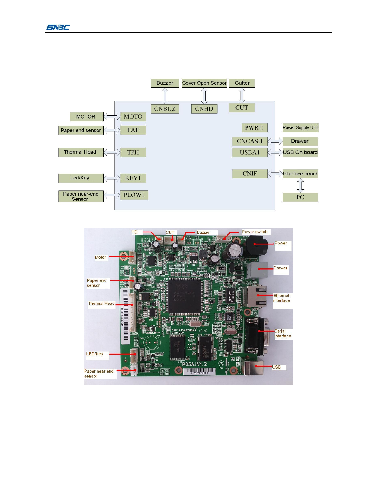
2.2 Main Control Board Unit Block Diagram
This printer uses main control board named POSJV1.2, the sensor, button, motor and cutter is connected
to main control board via connectors. The block diagram is shown as below:
Figure 2.2-1 Main control board unit block diagram
Figure 2.2-2 Position of each connector

BTP-R880NPII Service Manual
- 6 -
3 Communication interface
BTP-R880NPIIsupport RS232 serial interface, USB interface, Ethernet interface.
3.1 RS232 serial interface
3.1.1 Connector and specification
The printer serial interface is compatible with RS-232 standard, of which the outlet is 9PIN and the
connector is female DSUB-9 type.
3.1.2 Signal definition
Signal definition of 9pin interface is as below:
Pin
Signal name
Signal direction
Function
1
NC
—
NC
2
RXD
Input
Data Input
3
TXD
Output
Data input
4
DTR
Output
Require to Receive
5
GND
—
GND
6
DSR
Input
Require to send
7
RTS
Output
Require to Receive
8
CTS
Input
Require to send
9
+5V
Output
Not connected
3.1.3 Interface parameters
Parameters of the Serial interface module:
Item
Parameter
Data transfer
Serial
Synchronize method
Asynchronism
Handshaking
DTR/DSR or XON/XOFF
Pressure
MARK = -3 to –15 V: logic 1/ OFF
SPACE = +3 to +15 V: logic 0/ ON
Baud rate
1200,2400,4800,9600,19200,38400,57600,115200bps
Data bits
8bits
Stop bits
1bit
Notes:
All of the baud rates, data bits and parity bits of the serial interface can be configured by EEPROM.
3.1.4 Default Setting
Default configuration of the printer.(user can inquire the interface configuration by printing self test
page)
Baud rate: 9600bps
Data bits: 8bits
Parity bits: NO
Stop bits: 1bit

BTP-R880NPII Service Manual
- 7 -
Handshaking: Hardware
3.1.5 Timing sequence
The software handshake (XON/XOFF) timing sequence:
When XON/XOFF control is selected, the printer transmits XON or XOFF signals as follows.
Printer status
Action
XON
Transmission
1) When the printer goes online after turning on the power
2) When the receive buffer is released from the buffer full state
Transmit
Transmit
XOFF
Transmission
1) When the receive buffer becomes full
Transmit
Notes:
1) Definition of “receive buffer full”: default size of receive buffer is 4K (which can be set to 45Byte/64K).
When the buffer size is less than a certain amount (thenumber of bytes is n1) and the interface is serial,
receive buffer is full and keep full status. It is not full until the buffer size is increased to another certain
amount. (The number of bytes is more than n1).
2) Definition of XON/XOFF: XON is 0X11 and XOFF is 0X13.
The hardware handshake (XON/XOFF) timing sequence:
When hardware handshake is selected, the status of signal DTR/DSR is shown as below:
Printer status
Status
DTR
1) When power on the printer and the printer is on line.
SPACE
2) When receive buffer is released from full status.
SPACE
DSR
1) When receive buffer is full.
SPACE
3.1.6 Error processing
Error phenomena: Data can not be sent and received.
Error causes:
1) The cable is not connected reliably.
2) Theparameter setting is wrong.
3) The circuit is void welded or damaged.
Error detects and debugs:
1) Check whether the serial cable is connected reliably or not, if not, please connect it again.
2) Check whether the serial port setting of host is same as the printer configuration sheet or not, if
not, please configure the serial port setting again and send the data again.
3) Check whether the serial port signal is normal or not, If not, please check whether signal channel
is normal or not. If so, please check whether SU01 is void welded or not. If not, please replace
SU01.
3.2 USB interface
3.2.1 USB Interface Connector and Specifications
The USB Interface Connector is a standard USB B Interface Connector.
3.2.2 Signal Define of the USB Interface Module
Signal Define:

BTP-R880NPII Service Manual
- 8 -
Pin
signal
Signal define
1
VCC
Power
2
DATA+
Data +
3
DADA-
Data -
4
GND
Ground
3.2.3 Signal cable of USB interface module
USB interface cable adopts standard USBATO B cable, cable length1.5M. USB interface cable
accord with USB2.0 standard.
3.2.4 Parameters of the USB Interface Module
The USB interface supports USB2.0 protocol and can concatenate through USB HUB.
3.2.5 Troubleshooting of the Interface Module
Error phenomena: Data can not be sent out, data can not be received.
Error causes:
1) Cables are not connected securely.
2) Some parts on the USB interface circut are void welded or damage.
Error detects and debugs:
1) Change to a new USB cable and test again.
2) Check if the capacitors and resistors are welded normally. ReplaceU101 and testagain if they are
welded normally.

BTP-R880NPII Service Manual
- 9 -
3.3 Ethernet interface
3.3.1 Ethernet interface connector and specification
Theparameters of network interface socket match 10BASE-T standard of IEEE802.3.
3.3.2 Ethernet interface electric specification
Output signal: Efficient differential mode voltage more than 450mV, top voltage more than 13V.
Common mode alternating top voltage is less than 2.5V.
Input signal: differential mode voltage more than 160mV is regarded as efficient mode voltage.
3.3.3 Troubleshooting of the Interface Module
Detailed information please refer to Quick Reference to Ethernet Interface Module.
Pin
Signal name
Introduction
1
TX+
Data sending+
2
TX-
Data sending-
3
RX+
Data receiving +
4
NC
Reserve
5
NC
Reserve
6
RX-
Data receiving -
7
NC
Reserve
8
NC
Reserve

BTP-R880NPII Service Manual
- 10 -
4 Disassembly and Assembly
Caution:
1) Do not disassemble any parts of the printer or loosen any screw if it works properly;
2) When disassembling parts, please check carefully if the connecting lines are damaged or not;
3) When handling the thermal print head or electronic components, please make sure to use
antistatic gloves or bracelet;
4) During the disassembly, be careful not to leave small parts or screws inside the printer;
5) Don’t scratch the print head surface.
Assistant material: Lubricant, alcohol, absorbent cotton.
4.1 Maintainance tools
Screw Driver(Philips type)
Screw Driver (line type)
Wire clamp pliers
4.2 Disassemble the Printer
4.2.1 Disassemble bottom and top covers
Figure
Instruction
1.
Top view of printer
2.
Press the latch of the top cover and open it;
disassemble two ST2.6×6 self tapping screws.

BTP-R880NPII Service Manual
- 11 -
3.
Follow the arrows to push the hooks on the right and left
of the top cover so that it could be taken off the roller
bracket.
4.
Take off the top cover
5.
Follow the arrows to uplift the cutter cover and take it off

BTP-R880NPII Service Manual
- 12 -
6.
Unscrew two M3*5 screws which fix the middle body
7.
Take off the middle body
8.
Unscrew four M3*5 screws which fixthe lower body and
take off the lower body

BTP-R880NPII Service Manual
- 13 -
10.
Take off the lower body, separate it from the mechanism
and finish disassembling the printer housing
4.2.2 Disassemble lower board cover
Disassemble two ST2.9tapping screws and separate the
hook of the bottom circuit board cover from the circuit
board cover to take off the bottom circuit board cover.
4.2.3 Disassemble the main control board and the main control boardprotection film
Unscrew the four M3*5 screws fixing the main control
board and separate the main control board from the
mechanism.
Table of contents
Other SNBC Printer manuals


SNBC
SNBC KIOSK Series User manual

SNBC
SNBC BTP-R180II User manual

SNBC
SNBC BTP-R180II User manual

SNBC
SNBC BTP-R880NP Owner's manual

SNBC
SNBC BT-T080 Owner's manual

SNBC
SNBC BTP-M300 Owner's manual

SNBC
SNBC BK-S216 User manual

SNBC
SNBC BTP-2002NP User manual

SNBC
SNBC BTP-P33 User manual

SNBC
SNBC BK-T6112 User manual


