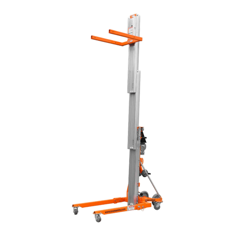
I
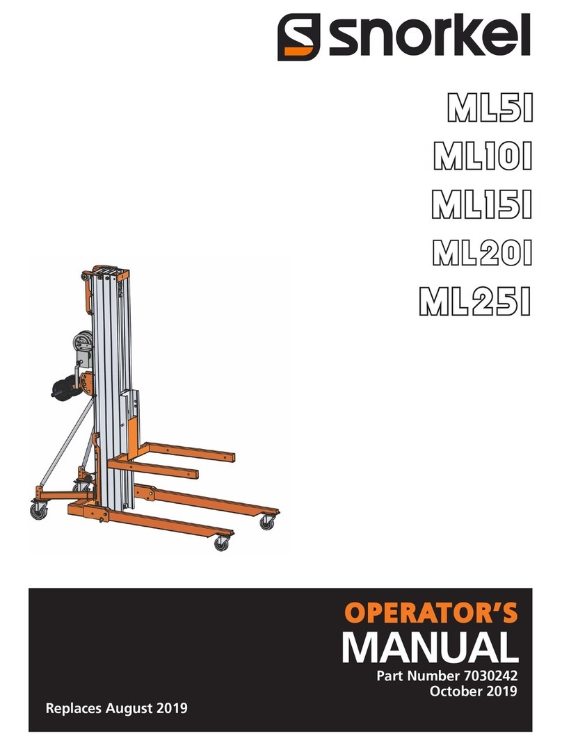
UL-25/32/40 Portable Personnel Lifts
Contents i
Section
Section Page
Number No.
Table of Contents
1.0 Introduction ............................................................. 1-1
Purpose of Equipment ........................................ 1-1
General Description............................................ 1-1
Platform............................................................ 1-1
Mast.................................................................. 1-1
Chassis.............................................................. 1-1
Operator Controls ............................................ 1-1
2.0 Introduction ............................................................. 4-1
Special Tools ...................................................... 4-1
2.1 Preventative Maintenance (Table 2-1) ................. 4-1
Preventative Maintenance Table Key............. 4-2
Preventative Maintenance Report................... 4-2
2.2 Lubrication............................................................... 4-3
Casters................................................................. 4-3
Chains ................................................................. 4-3
Screw Jacks......................................................... 4-3
Hydraulic Oil Reservoir (Figure 2-2) ................ 4-3
2.3 Battery Maintenance
(DC units only)........................................................ 4-4
Battery Inspection and Cleaning........................ 4-4
Battery Charging (Figure 2-3) ........................... 4-4
Battery Cell Equalization................................... 4-5
2.5 Mast Assembly (Figure 2-6,2-7) Disassembly ...... 4-6
Platform Assembly Removal
(Figure 2-6) ..................................................... 4-6
#6 Mast............................................................. 4-6
#5 Mast............................................................. 4-6
#4 Mast............................................................. 4-6
2.5 Mast Assembly (Cont.)............................................ 4-9
#3 Mast............................................................. 4-9
#2 Mast............................................................. 4-9
Assembly (Figure 2-7)........................................ 4-9
#2 Mast............................................................. 4-9
#3 Mast............................................................. 4-9
#4 Mast............................................................. 4-9
#5 Mast............................................................. 4-9
#6 Mast............................................................. 4-9
2.5 Mast Assembly (Cont.)............................................ 4-10
Platform Support Assembly ............................ 4-10
Sequencing Strap Installation ......................... 4-10
2.6 Cylinder Assembly .................................................. 4-10
Seal Replacement (Figure 2-8) .......................... 4-10
2.6 Cylinder Assembly (Cont.) ..................................... 4-12
Orifice Valve Cleaning ...................................... 4-12
Cylinder Removal (Figure 2-9).......................... 4-13
Installation .......................................................... 4-13
2.6 Cylinder Assembly (Cont.) ..................................... 4-14
Installation (Cont.) ............................................. 4-14
Fasteners ............................................................. 4-14
2.7 Torque Specifications.............................................. 4-14
Hydraulic Components....................................... 4-14
3.0 Introduction ............................................................. 5-1
General Procedure .............................................. 5-1
4.0 Introduction ............................................................. 6-1
Index.................................................................... 6-1
4.1 Electrical Schematics .............................................. 6-2
4.2 Hydraulic Schematic............................................... 6-4
Table Page
Number No.
1-1 Specifications ............................................................. 1-2
2-1 Preventative Maintenance ......................................... 2-2
2-2 Hydraulic Component Torque.................................. 2-14
2-2 Bolt Torque ................................................................ 2-14
3-1 Troubleshooting ......................................................... 3-2
4-1 Electrical Schematic Legend, AC ............................. 4-2
4-2 Electrical Schematic Legend, DC ............................. 4-2
4-3 Hydraulic Schematic Legend .................................... 4-4
Figure Page
Number No.
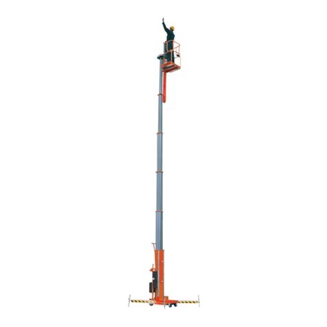
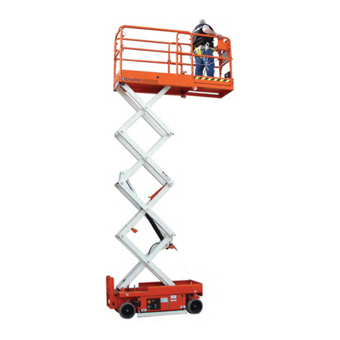
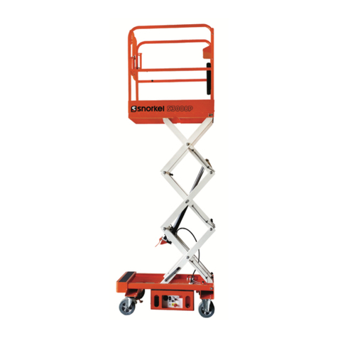
1-1 UL Portable Personnel Lifts ...................................... 1-1
2-1 Lubrication ................................................................. 2-3
2-2 Hydraulic Power Unit ................................................ 2-3
2-3 Battery Charger .......................................................... 2-5
2-4 System Relief Valve .................................................. 2-5
2-5 Lifting / Lowering UL Lift........................................ 2-6
2-6 Mast Assembly, Strap and Chain Detail ................... 2-7
2-7 Mast Assembly Bearing Detail ................................. 2-8
2-8 Lift Cylinder............................................................... 2-11
2-9 Chain Tensioning, Cylinder Installation................... 2-13
3-1 Circuit Board.............................................................. 3-5
3-1 Electrical Schematic, AC Models ............................. 3-3
3-2 Electrical Schematic, DC Models ............................. 3-3
3-3 Hydraulic Schematic.................................................. 3-4
List of Illustrations
List of Tables
