manuals.online logo
Brands
  1. Home
  2. •
  3. Brands
  4. •
  5. Solas
  6. •
  7. Fireplace Accessories
  8. •
  9. Solas SEVENTY2 LGS-72 User manual

Solas SEVENTY2 LGS-72 User manual

0
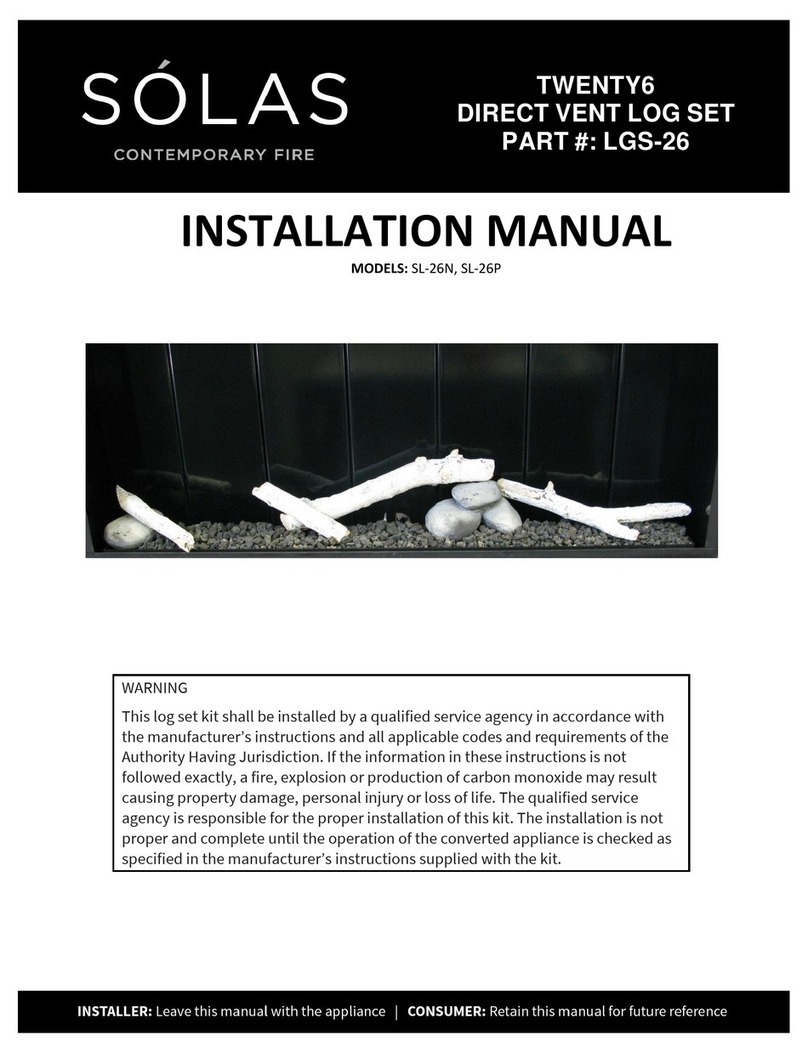
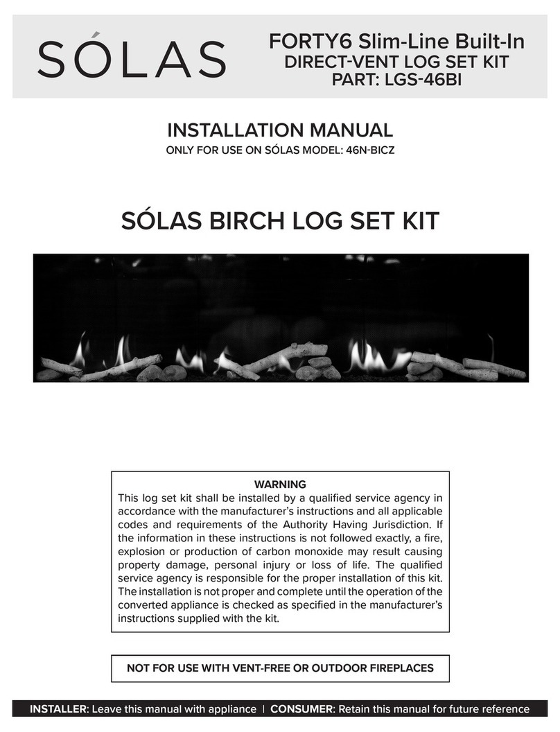
INSTALLATION MANUAL
ONLY FOR USE ON SÓLAS MODELS: 72N-SSL, 72P-SSR, 72N-ST, 72P-SSL, 72P-SSR, 72P-ST
SEVENTY2
DIRECT VENT LOG SET KIT
PART #: LGS-72
WARNING
This log set kit shall be installed by a qualified service agency in accordance with
the manufacturer’s instructions and all a licable codes and requirements of the
Authority Having Jurisdiction. If the information in these instructions is not
followed exactly, a fire, ex losion or roduction of carbon monoxide may result
causing ro erty damage, ersonal injury or loss of life. The qualified service
agency is res onsible for the ro er installation of this kit. The installation is not
ro er and com lete until the o eration of the converted a liance is checked as
s ecified in the manufacturer’s instructions su lied with the kit.
NOT FOR USE WITH VENT FREE OR OUTDOOR FIREPLACES
1
LOG SET INSTALLATION
Kit Contents:
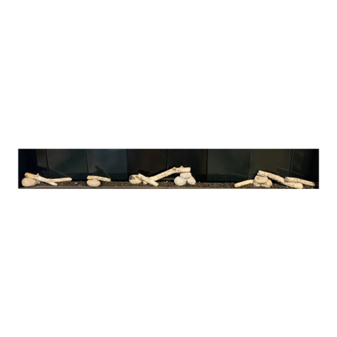
•(5) Ceramic Logs
•(6) Ceramic Rocks
•2lb 0oz Lava Rock
•Metal Logset burner set
Figure 01 - Burner Support locations
Step #1
Your fire lace will have shi ed from the factory with the Glass Media burners in lace, before
installing the logset burners, we need to remove the glass burners. The left and right burners are each
held in lace by 6 sheet metal screws, and a central link which ties the 2 burners together. Each burner
su ort is secured by 2 sheet metal screws, each burner has 3 burner su orts (see figure 01). In all, to
remove both burners, you will be removing 14 sheet metal screws. Begin by removing the central burner
link, which secures both burners to each other, identified by the large arrow in figure 03.
Step #2
To remove the left burner, begin by removing the burner link identified by the large arrow below.
Once the central burner link has been removed, remove the 6 sheet metal screws securing the left
burner, these screws are identified by the 6 smaller arrows below. Once all hardware has been removed,
slide the burner to the left and lift the burner out of the fire lace.
Figure 02
2
LOG SET INSTALLATION
Step #3
To remove the right burner, remove the 6 sheet metal screws securing the right burner, these
screws are identified by the 6 arrows below. Once all hardware has been removed, slide the burner to
the right and lift the burner out of the fire lace.
Figure 03
Step #5
Once the glass media burner has been removed, locate the Logset burner included in the kit LGS-72 and
install in the fire lace reusing the hardware removed during disassembly.
NOTE:
The logset burner can be configured for either Natural Gas or Pro ane by installing or removing
a collar on the burner venturi. Figure 04 shows the venturi inlet with the collar installed on a burner
configured for Natural Gas. Figure 05 shows the venturi inlet with the collar removed from a burner
configured for Pro ane. THIS ENTURI IS NOT ADJUSTABLE. If you need to convert your burner
from Pro ane to Natural Gas or vice-versa, lease order the a ro riate conversion kit for your
a liance.
Configured for
Natural Gas
Configured for Propane
IGURE 0
5
IGURE 0
4
3
LOG SET INSTALLATION
Step #6
Install the left logset burner within the firebox by lowering the burner into the firebox.(while kee ing the
burner ressed toward the left side of the firebox) then sliding the burner right towards the center of the
firebox to engage the burner orifice. Confirm that the burner inlet tube has engaged the burner orifice.
Secure the burner using the (6) sheet metal screws set aside from ste s 1-3.
Figure 06
Step #7
Install the right logset burner within the firebox by lowering the burner into the firebox.(while kee ing
the burner ressed toward the right side of the firebox) then sliding the burner left towards the center of
the firebox to engage the burner orifice. Confirm that the burner inlet tube has engaged the burner
orifice. Secure the burner using the (6) sheet metal screws set aside from ste s 1-3.
Figure 07
Step #8
Secure the central burner link using the (2) sheet metal screws from ste #2.
Figure 08
4
LOG SET INSTALLATION
Step #9
Install the 3-rock cluster on the 2 ins located at the far left of the firebox as shown in figure 09.
Figure 09
Step #10
Install these two rocks shown in figure 10 on the ins slightly to the right of the 3-rock cluster you
installed in ste 9.
Figure 10
Step #11
Install the 3-rock cluster as shown in figure 11 on the ins to the right of the ilot assembly, towards the
back of the burner.
Figure 11
5
LOG SET INSTALLATION
Step #12
Install the 3-rock cluster shown in figure 12 to the right of the cluster installed in ste 11.
Figure 12
Step #13
Install the middle birch log set by lacing the right side of the log on the 3-rock cluster you installed in
ste #11. The left side of the log engages with the in located to the left of the ilot assembly.
Figure 13
6
LOG SET INSTALLATION
Step #14
Install the log shown in figure 14 with the left side resting on the 3-rock cluster you installed in ste 9.
The right side of the log rests on the burner as shown located by a in.
Figure #14
Step #15
Install the log shown in figure 15 with the right side resting on the 2 rocks installed in ste 10. The left
side of the log rests on the burner as shown located by 2 ins.
Figure #15
7
LOG SET INSTALLATION
Step #16
Install the log shown in figure 16 with the left side resting on the 3-rock cluster installed in ste 12. The
rock is located by a single in and aligned arallel to the front edge of the burner. The log rests on the
rock as shown, the right side is located by 2 ins on the burner.
Figure #16
Step #17
Install the single rock and log shown in figure 17, the rock is located by a single in and aligned arallel
to the front edge of the burner with the left side of the log resting on to . The right side of the log rests
on the burner, a groove in the underside of the log interfaces with the front edge of the burner, slide the
log to the right until the ti of the log is about to make contact with the enamel side anel.
Figure #17
8
LOG SET INSTALLATION
Step #18
Evenly distribute the included 2lb and 0oz of lava rock on the ex osed burner to . Cover the burner to
com letely but do not com ress or “ ack” the lava rock tightly. Pay s ecial attention to tight and hard
to reach areas when lacing the media on the burner. It is ok if small amounts of lava rock are lost over
the edge of the burner.
Installation of the log set is now complete, refer to the SE ENTY2 owner’s manual for instructions
on final assembly and lighting of the appliance.

Other manuals for SEVENTY2 LGS-72

2

Other Solas Fireplace Accessories manuals
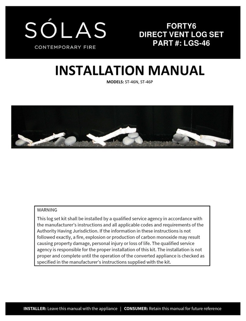
Solas TWENTY6 SL-26N User manual

Solas

Solas TWENTY6 SL-26N User manual

Solas SIXTY0 LGS-60 User manual

Solas

Solas SIXTY0 LGS-60 User manual

Solas SEVENTY2 LGS-72 User manual

Solas

Solas SEVENTY2 LGS-72 User manual

Solas Twenty6 FI User manual

Solas

Solas Twenty6 FI User manual

Solas ONE6 User manual

Solas

Solas ONE6 User manual

Solas ONE6 User manual

Solas

Solas ONE6 User manual

Solas Helios Pulse User manual

Solas

Solas Helios Pulse User manual

Solas ST-46N User manual

Solas

Solas ST-46N User manual

Solas TWENTY6 LGS-26BI User manual

Solas

Solas TWENTY6 LGS-26BI User manual

Solas FORTY6 LGS-46BI User manual

Solas

Solas FORTY6 LGS-46BI User manual

Solas BI-48-ST Owner's manual

Solas

Solas BI-48-ST Owner's manual

Solas LGS-48 User manual

Solas

Solas LGS-48 User manual

Solas ONE6 User manual

Solas

Solas ONE6 User manual
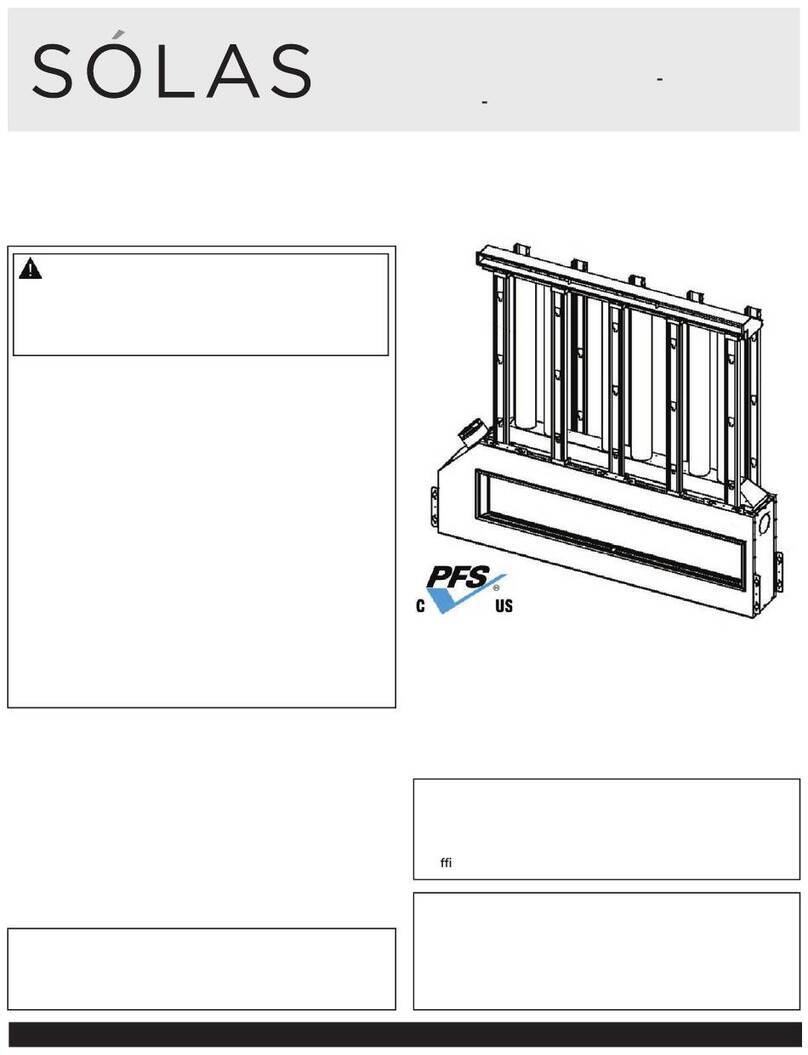
Popular Fireplace Accessories manuals by other brands

Valor LT1 2500K quick start guide

Valor

Valor LT1 2500K quick start guide

IHP PCBE-36 Operation manual

IHP

IHP PCBE-36 Operation manual

Woodstock Soapstone W-232 Replacement manual

Woodstock Soapstone

Woodstock Soapstone W-232 Replacement manual

Lennox Hearth Products Elite Series installation instructions

Lennox Hearth Products

Lennox Hearth Products Elite Series installation instructions

New Buck Corporation 42ZCBB user guide

New Buck Corporation

New Buck Corporation 42ZCBB user guide

IHP AK4 quick start guide

IHP

IHP AK4 quick start guide

Napoleon NEFE30-3820AW Installation and operation manual

Napoleon

Napoleon NEFE30-3820AW Installation and operation manual

Valor G4 791STB installation manual

Valor

Valor G4 791STB installation manual

Stove Guard Guardian 2010 Installation & operating manual

Stove Guard

Stove Guard Guardian 2010 Installation & operating manual

Monessen Hearth BO18-R Installation and operating instructions
Monessen Hearth

Monessen Hearth BO18-R Installation and operating instructions

Travis Industries 250-05727 quick start guide

Travis Industries

Travis Industries 250-05727 quick start guide

pleasant hearth Log Hoop LS932-HP quick start guide

pleasant hearth

pleasant hearth Log Hoop LS932-HP quick start guide

Napoleon NEFM33-0314BW Installation and operating instructions

Napoleon

Napoleon NEFM33-0314BW Installation and operating instructions

Valor Legend G3 739NGK installation instructions

Valor

Valor Legend G3 739NGK installation instructions

HPC MLFPK Series Installation & operation instructions

HPC

HPC MLFPK Series Installation & operation instructions

Toplicht HAMLET SOLUTION S4 Outside Air Kit Fittings guide

Toplicht

Toplicht HAMLET SOLUTION S4 Outside Air Kit Fittings guide

kozy heat KZK-052 manual

kozy heat

kozy heat KZK-052 manual

FireplaceXtrordinair 96100838 Installation

FireplaceXtrordinair

FireplaceXtrordinair 96100838 Installation

manuals.online logo
manuals.online logoBrands
  • About & Mission
  • Contact us
  • Privacy Policy
  • Terms and Conditions

Copyright 2025 Manuals.Online. All Rights Reserved.