Sony RMU-01 User manual

4-177-133-14 (1)
© 2010 Sony Corporation
Remote Control Unit
Operating Instructions
Before operating the unit, please read this manual thoroughly
and retain it for future reference.
RMU-01

2Table of Contents
Table of Contents
Overview .........................................3
Parts Identifications .......................4
Making Use of the NT Remote
Function ........................................... 5
Installations ..................................... 8
Attaching to the Microphone
Stand .........................................8
Attaching on the Wall ...............9
Attaching to the Catwalk, Pole,
or a Lighting Battens ..............10
Preparations of Operation ...........11
Using the RMU-01 Setting
Tool ................................................11
Preparations ............................12
Starting Up and Exiting the
Software ..................................13
Parts Identification .................13
Detecting the RMU-01 Units on
the Network Automatically ....15
Changing the Settings of the
RMU-01 ..................................15
Additional Functions ..............17
Connecting to Power Supply and
Other Devices ................................19
Supplying Power From the PoE
Device .....................................19
Supplying Power From the AC
Adapter ...................................20
Troubleshooting............................ 21
On the Status of This Unit and
the Lighting Status of the
POWER Indicator ...................22
Important Notes on Operation .... 23
On Power Supply ....................23
On Installation ........................23
On Operation ..........................23
On Using and Storing
Environment ........................... 23
On Cleaning ........................... 23
Specifications ................................ 24

3
Overview
Overview
The RMU-01 Remote Control Unit can be
used for a network remote control (referred
to as “NT remote,” hereafter) of the Sony
wireless microphone system.
• By connecting this unit through the LAN
cable and placing at appropriate location,
the transmitters can be controlled
remotely and the NT remote system
operation that is capable of controlling up
to 82 transmitters is highly utilized.
Up to nine RMU-01 units can be used
with one system.
• This unit accepts PoE (Power over
Ethernet) that makes long-distance LAN
connections easy. The power to this unit
can also be provided from the supplied
AC adapter.
• Inside a solid structure, a 1/4 wavelength
monopole antenna is built into this unit.
The smooth surface of this unit is
designed to match various installation
locations. This unit can easily be attached
to the microphone stand. With the
supplied brackets, this unit can also be
attached on the wall, poles, lighting
battens, catwalk, etc.
• Using more of this unit in the network
system does not necessarily increase the
number of controllable transmitters. The
maximum number of controllable
transmitters in the system is 82,
regardless of the number of this unit.
For details on installation location, installation
intervals, and cables for connections, see
“Important Notes on Operation” on page 23.
• If you plan to use a PoE hub or PoE
power supply unit, purchase it on the
market.
For details on how to connect the receivers, PoE
devices, hub, etc., refer to the operation manual
supplied with the applicable device.
What is the PoE (Power over
Ethernet)?
The PoE is a technology to supply power
through the Ethernet cable used for LAN
connection. With LAN cables carrying both
signal and power, operation in a situation
where the power supply is difficult to
reserve becomes easy.
The power can be supplied to this unit from
the connected PoE hub that conforms to
IEEE802.3af standards, or from the PoE
power supply device connected to this unit
through the hub.
Notes

4Parts Identifications
Parts
Identifications
aAntenna storage section
bHole for attaching the microphone
stand
Can be attached to the microphone stand
(PF 1/2-inch thread) with this hole.
To attach an NS 5/8-inch or a W 3/8-inch
microphone stand, use the supplied screw
adapter.
cAC adapter connector and POWER
indicator
Connect the supplied AC adapter to the AC
adapter connector to supply power to this
unit.
The POWER indicator lights up green
while the power is supplied from the AC
power connector or the LAN connector.
For details on power supply to this unit, see
“Connecting to Power Supply and Other Devices”
on page 19.
dLAN connector (RJ-45)
This is a 10Base-T/100Base-TX connector
for network connection. Communication
speed automatically changes according to
the connected device.
Connect to a receiver such as DWR-R01D,
Windows PC, or hub.
When a PoE device including PoE hub is
connected, the power is supplied through
this connector.
• For safety, do not connect the connector
for peripheral device wiring that might
have excessive voltage to this port.
Follow the instructions for this port.
• Do not touch the LAN connector directly
with your hand. If you do, electrostatic
discharge may damage the internal
components.
Front side
Bottom side
CAUTION

5
Making Use of the NT Remote Function
Making Use of the
NT Remote
Function
To use the NT remote function fully and
with stability, note the following.
• 2.4GHz-band radiowave has the strong
tendency to travel in a straight line. When
there is an obstacle between this unit and
the transmitter, signal strength drops
rapidly. To avoid this, be sure to install
this unit so that this unit is in direct view
from where the transmitters are placed.
• In order to avoid signal interference and
to maintain stable 2.4GHz-band
transmission, it is recommended to use at
least two RMU-01 units in the network.
When installing multiple RMU-01 units,
install them so that they keep distance of
10 m to 20 m (11 yards to 22 yards) from
one another.
• Up to nine RMU-01 units can be
connected to a system. Under less
favorable environment where the signal
is weak due to signal interference,
consider adding more RMU-01 units to
reinforce the signal transmission, if
necessary.
• When operating outdoors where less
signal reflection occurs than indoors,
operating area of this unit may be
narrowed. For outdoor use, install this
unit at the same height as the transmitters
to shorten the signal transmission
distance.
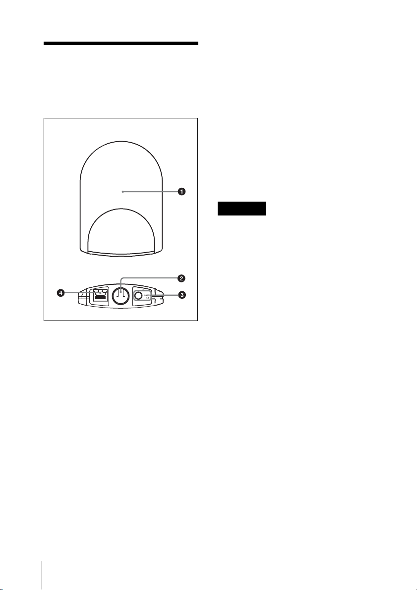
• In every operating environment, the
internal antenna of this unit attains
efficient performance with the side with
connectors facing downward. However,
when this unit is installed close to the
ceiling, better performance can be
obtained by facing the front side (the side
with SONY logo) downward.
• Signal transmission status varies
depending on the structure and material
of the building where this unit is
installed. It is recommended to install this
unit so that the wireless remote control
condition level indications on the
transmitters and receivers (Shows the
quality of 2.4-GHz wireless signal. For
details, refer to the Operating
Instructions supplied with the wireless
microphone, transmitter, or the receiver.)
are stable at or .
• When the total operation area is wide by
putting together the areas that two or
more RMU-01 units cover, the
transmitter may change the RMU-01 unit
to communicate with from one to another
(roaming). Even when the areas that the
RMU-01 units cover are completely
adjacent with no gaps, the
communication between the transmitter
and the receiver is cut whenever the
roaming occurs on the transmitter. Note
that the communication is cut for several
seconds.
About the characteristics of
the built-in antenna
The antenna inside the casing of this unit
emits the strong radiowave concentrically
from the center of the antenna. Placing the
transmitter inside the radiowave circle is
important for taking advantage of the
system.

6Making Use of the NT Remote Function
Emitted radiowave is strong in the area
inside the radius of approximately 10 m
(33 feet). When installing multiple RMU-
01 units, place them so that strong signal
area touches that of adjacent RMU-01 unit.
Installation example 1 (plane view)
When two RMU-01 units are installed to
control the body-pack transmitter that is
worn around the waist of a person, it is
recommended that the RMU-01 units be
placed across the body-pack transmitter so
that there is no obstacle between the
transmitter and at least one of the RMU-01
units.
Installation example 2 (plane view)
To increase the total operation area by
putting the areas that multiple RMU-01
units cover together, place them so that the
area that one RMU-01 covers touches those
on others, completely adjacent and with no
gaps.
Installation example 3 (section
view)
This is an example when this unit is
installed to the microphone stand.
Antenna (inside
the casing)
1) Radius: approx. 10 m (33 feet)
2) Front side (the side with SONY logo)
1) RMU-01
2) Transmitter worn around the waist of a
person
1) RMU-01
2) Transmitter

7
Making Use of the NT Remote Function
Indoors: Because the signal is reflected
from the walls, floor, and ceiling, there are
no conditions for the installation height of
this unit.
Outdoors: Install this unit at the same
height as the transmitters.
Installation example 4 (section
view)
This is an example when this unit is
installed on the wall.
Indoors: Because the signal is reflected
from the walls, floor, and ceiling, there are
no conditions for the installation height of
this unit.
Outdoors: Install this unit at the same
height as the transmitters.
Installation example 5 (section
view)
This is an example when this unit is
installed indoors, near the ceiling.
1) RMU-01
2) Transmitter
3) Floor
1) RMU-01
2) Transmitter
3) Wall
4) Floor
1) RMU-01
2) Transmitter
3) To make the most of the signal emission
characteristics, install facing the front
side (the side with SONY logo)
downward.
4) Ceiling
5) Wall
6) Floor

8Installations
Installations
Attaching to the
Microphone Stand
1Attach the cable holder to this unit.
2When attaching to an NS 5/8-inch or a
W 3/8-inch microphone stand, screw in
the supplied screw adapter into the
hole for attaching the microphone
stand.
3Insert the tip of the microphone stand
into the hole, and turn this unit to
securely attach to the microphone
stand.
4Connect the cables.
For details on connections, see “Connecting
to Power Supply and Other Devices” on
page 19.
5Bring the cables together with the
cable holder.
Rear side of
this unit
Cable holder
(supplied)
Screws (supplied)
Screw adapter
(supplied)
Microphone stand

9
Installations
Attaching on the Wall
Do not touch the LAN connector directly
with your hand. If you do, electrostatic
discharge may damage the internal
components. To prevent this unit from
electrostatic damage, grounding the
supplied brackets, safety wire, etc., by
attaching them to metallic object is
recommended.
1Attach the bracket Aon the wall
securely with screws.
2Attach the bracket Band the cable
holder to this unit.
3Make connections and bring the cables
together with the cable holder.
For details on connections, see “Connecting
to Power Supply and Other Devices” on
page 19.
4Wrap the supplied safety wire around
the bracket B.
5Join the brackets by pressing down the
two hooks on the bracket Bagainst
the two square holes on the bracket A,
Note
Cable holder
(supplied)
Bracket A(supplied)
Rear side of
this unit
Bracket B
(supplied)
Cable holder
(supplied)
Screws (supplied)
Safety wire (supplied)

10 Installations
until the upper edges of the brackets
align.
Take care not to catch the cables
between the brackets.
6Fix the end of the safety wire to the
wall with a screw.
7Screw in the supplied screw adapter
into the hole for attaching the
microphone stand to secure the bracket
Ato this unit.
Attaching to the Catwalk,
Pole, or a Lighting Battens
1Attach the bracket Ato the location
where this unit is attached by using
banding bands.
2Do steps 2to 7in “Attaching on the
Wall” on page 9.
Note
Bracket B
(supplied)
Bracket A(supplied)
Safety wire (supplied)
Bracket A
(supplied)
Screw adapter
(supplied)

11
Preparations of Operation / Using the RMU-01 Setting Tool
Preparations of
Operation
Do the procedure below to prepare the
operation in NT remote system.
1Install the RMU-01 Setting Tool
software on the PC.
For details on installing procedure, refer to
the printed Operating Instructions.
2Connect this unit to the PC with the
RMU-01 Setting Tool installed with a
LAN cable.
At this point, the connection to the
DWR-R01D is unnecessary.
3Set the IP address of this unit by using
the RMU-01 Setting Tool software.
For details, see “Using the RMU-01 Setting
Tool” on page 11.
4Connect the PoE hub or PoE power
supply unit and the DWR-R01D, etc.,
to this unit.
For details on the power supply to the unit, see
“Connecting to Power Supply and Other
Devices” on page 19.
For details on system configuration examples,
refer to the Operating Instructions supplied
with the DWR-R01D.
Using the RMU-01
Setting Tool
Depending on the PC environment, an
attempt to start up the RMU-01 Setting
Tool software may be blocked by the
firewall. When the firewall is activated for
the RMU-01 Setting Tool software, LAN
communication necessary for the NT
remote function is blocked, resulting in the
operational failure of this unit. To prevent
this from happening, set the firewall so that
the RMU-01 Setting Tool software is
unblocked.
This section explains the use of the Setting
Tool software supplied with the RMU-01
Remote Control Unit.
Notations Used in This User’s
Guide
• Clicking a menu or button and then
selecting a sub-menu is expressed as
follows: Select “Menu (or button) > (sub-
menu name)”.
Example: Select “File menu>New”.
• Holding down one key on the keyboard
while pressing another is indicated by a
“+” sign between the two keys.
Example: Press Ctrl + C.
About the Window Displays
The window displays that appear in this
section may differ from those on your PC,
due to differences in the operating system
being used.
Note

12 Using the RMU-01 Setting Tool
Preparations
Connections
Connect the RMU-01 to the PC with a LAN
cable.
For connections, use a category 5 or
superior LAN cable with a maximum length
of 100 m (330 ft).
The type of LAN cable for the connection
differs depending on how to connect the
RMU-01 to the PC, as follows:
To connect the PC directly: cross cable
To connect the PC through the hub:
straight cable
For details on how to connect the RMU-01 to other
devices, see “Connecting to Power Supply and
Other Devices” on page 19.
Settings up the network
Make network settings on the RMU-01 and
the PC.
For the PC to recognize other devices on the
network, host name, IP address, and subnet
mask must be specified to all the devices to
be connected to the network.
The following table shows the setting
examples for connecting two RMU-01 units
and the PC.
1) The IP addresses of the RMU-01 units do not
need to be consecutive.
2) Normally, specify “255.255.255.0”.
Make sure not to use an IP address that is
already assigned to another device on the
network. If you do, the devices with the
same IP address may not pe recognized.
PC network settings
The following procedure explains the
setting operations using the Windows XP
operating system.
For details on how to make network settings with
other operating systems, refer to the help of the
operating system that you use.
1Select “Start>Control Panel>Network
and Internet Connections”.
2Click “Network Connections”.
3Right-click the local area connection
icon and then click “Properties”.
4Double-click “Internet Protocol 4
(TCP/IP)”.
The properties window of the local
area connection opens up.
5Double-click “Internet Protocol (TCP/
IP)”.
The internet protocol (TCP/IP)
properties window opens up.
Device IP address Subnet
mask
PC 192.168.0.200 255.255.
255.0 2)
First
RMU-01 192.168.0.100 1)
Second
RMU-01 192.168.0.101 1)
Note

13
Using the RMU-01 Setting Tool
6Click “Use the following IP address”,
and then enter the IP address in the IP
address field.
Make sure not to use an IP address that
is already assigned to another device
on the network.
7Enter “255 255 255 0” into the Subnet
Mask field.
8Click “OK” to close the internet
protocol (TCP/IP) properties window.
9Click “Close” to close the local area
connection properties window.
Software installation
For details on installing procedure, refer to the
printed Operating Instructions.
Starting Up and Exiting the
Software
To start up the software
Select “Start> All Programs> Sony>
Digital Wireless Microphone System>
RMU-01 Setting Tool” to start up the
software.
To exit the software
Click the Close button (×) in the top-right
corner of the window.
Parts Identification
In this section, parts of the main display of this software are explained.
Note
2Setting button
3Option button
9Target TX setting display
6IP Address setting display
5MAC address display
4Name setting display
qa Version display
7Subnet Mask setting display
1Search Devices button
0Remote CH setting display
8Location setting display

14 Using the RMU-01 Setting Tool
aSearch Devices button
Click to detect the RMU-01 units on the
network.
For details, see “Detecting the RMU-01 Units on the
Network Automatically” on page 15.
bSetting button
Click to change the device name, IP
address, and subnet mask settings of the
device.
For details, see “Changing the Settings of the RMU-
01” on page 15.
cOption button
Click to activate additional functions.
dName setting display
Shows the names configured for the RMU-
01 units on the network.
A 16-character name is given to each RMU-
01 at the factory. With this software, the
RMU-01 units can be renamed.
For details, see “Changing the Settings of the RMU-
01” on page 15.
eMAC address display
Shows the MAC addresses of the RMU-01
units on the network.
Unique MAC addresses are given to each
device and cannot be changed.
fIP Address setting display
Shows the IP addresses configured for the
RMU-01 units on the network.
Initially, the factory-set value (192.168.0.2)
is displayed for all RMU-01 units. Be sure
to configure a unique IP address for each
device connected to the network. If two or
more devices share the same IP address,
they will not be recognized properly on the
network.
For details, see “Changing the Settings of the RMU-
01” on page 15.
gSubnet Mask setting display
Shows the subnet masks configured for the
RMU-01 units on the network.
Initially, the factory-set value
(255.255.255.0) is displayed for all RMU-
01 units. With this software, the settings can
later be changed.
For details, see “Changing the Settings of the RMU-
01” on page 15.
hLocation (region of use) setting
display
This function appears when version 1.23 or
later of the RMU-01 software is used with
version 1.12 or later of the Setting Tool
software.
This shows the region of use setting.
Configure this setting according your
region of use.
Initially, the factory-set value is displayed
for all RMU-01 units, but the setting can be
changed using this software.
For details, see “Changing the Settings of the RMU-
01” on page 15.
iTarget TX (target transmitter for
control) setting display
This function appears when version 1.10 or
later of the RMU-01 software is used with
version 1.10 or later of the Setting Tool
software.
In addition, when version 1.23 or later of
the RMU-01 software is used with version
1.12 or later of the Setting Tool software,
you can select multiple transmitters as
targets for control.
Configure this setting according to the
transmitter that will be remote controlled by
the RMU-01.
For details, see “Changing the Settings of the RMU-
01” on page 15.

15
Using the RMU-01 Setting Tool
jRemote CH (remote channel) setting
display
This function appears when version 1.10 or
later of the RMU-01 software is used with
version 1.10 or later of the Setting Tool
software.
This shows the channel configured to be
used by the RMU-01 for remote control.
Initially, the factory-set channel is
displayed for all RMU-01 units, but the
setting can be changed using this software.
For details, see “Changing the Settings of the RMU-
01” on page 15.
kVersion display
This function appears when version 1.10 or
later of the RMU-01 software is used with
version 1.10 or later of the Setting Tool
software.
This shows the software versions of the
RMU-01 units on the network.
Detecting the RMU-01
Units on the Network
Automatically
Click the Search Devices button to initiate
the automatic detection of RMU-01 units on
the network.
While the automatic detection is in
progress, the progress bar window appears.
When the detection finishes, information on
the detected RMU-01 units is listed in the
main window.
With some PC’s equipped with multiple
LAN ports (wired and wireless), the RMU-
01 units connected to a LAN port may not
be automatically detected even when you
click the Search Devices button.
If this happens, invalidate all ports
including LAN and IEEE1394 ports with
“Network Connections” on the OS, then
validate only the LAN port to which the
RMU-01 units are connected. And then,
restart the RMU-01 Setting Tool software
to perform automatic detection.
Changing the Settings of
the RMU-01
On the list of detected RMU-01 units in the
main display, click the name of the device
whose settings you want to change and
click the Setting button.
The Setting window for the device appears.
Changing the network
settings
To change the RMU-01’s name
Enter a new name in the Name box. Up to
16 characters can be entered.
The following characters and a space can be
used.
A B C D E F G H I J K L M N O P Q R S T
U V W X Y Z
0 1 2 3 4 5 6 7 8 9 ! # & $ @ + - = _ ( ) [ ]
Note

16 Using the RMU-01 Setting Tool
To change the IP address
Enter a new IP address in the IP Address
boxes. Up to three digits can be entered in
each box.
To change the subnet mask
Enter a new subnet mask in the Subnet
Mask boxes. Up to three digits can be
entered in each box.
Changing the remote control
settings
This function appears when version 1.10 or
later of the RMU-01 software is used with
version 1.10 or later of the Setting Tool
software.
In addition, when version 1.23 or later of
the RMU-01 software is used with version
1.12 or later of the Setting Tool software,
you can select multiple transmitters as
targets for control.
To change the region of use
setting
This function appears when version 1.23 or
later of the RMU-01 software is used with
version 1.12 or later of the Setting Tool
software.
Use the Location setting to select the region
of use. Configure this setting according
your region of use.
Changing the target transmitter for
control
Use the Target TX setting to select the
model number of the transmitter that will be
controlled by the RMU-01. Refer to the list
of transmitter model numbers in the
following tables, and change the setting
according to the transmitter you want to
use.
In addition, when version 1.23 or later of
the RMU-01 software is used with version
1.12 or later of the Setting Tool software,
you can select multiple transmitters as
targets for control.
US models
European models
Model
No.
Frequency
band
Frequency
U1424 TV14-17 470.125 -
493.875 MHz
TV18-21 494.125 -
517.875 MHz
TV22-25 518.125 -
541.875 MHz
U3040 TV30-33 566.125 -
589.875 MHz
TV34-36 590.125 -
607.875 MHz
TV37 Not available
TV38-41 614.125 -
637.875 MHz
U4250 TV42-45 638.125 -
661.875 MHz
TV46-49 662.125 -
685.875 MHz
TV50-51 686.125 -
697.875 MHz
Model
No.
Frequency
band
Frequency
CE3338 TV33-35 566.025 -
590.000 MHz
TV36-37 590.025 -
606.000 MHz
TV38-40 606.025 -
630.000 MHz
CE4248 TV42-44 638.025 -
662.000 MHz
TV45-47 662.025 -
686.000 MHz
TV48-50 686.025 -
710.000 MHz

17
Using the RMU-01 Setting Tool
Changing the remote control
channel settings
The optimal channel for remote control of
the transmitter selected with the Target TX
setting will be automatically selected and
displayed under Remote CH.
You can select the Custom setting to enable
selection of remote control channels.
By selecting Custom and selecting a remote
control channel, you may be able to prevent
interference that may occur between the
RMU-01 and other wireless LAN systems
during remote control.
When the Custom setting is used, the
automatically selected optimal remote
control channel for the transmitter you are
using will be ignored. In such cases, signals
sent from the transmitter may have an effect
on remote control. Be sure to confirm
operation before using the setting.
After changes are made, click OK to enter
the new settings and revert to the main
display.
If the new settings are valid, a message
indicating that setting is complete will
appear. If the settings are invalid, an error
message appears. Follow the instructions in
the error message to correct the settings.
To change settings of the
RMU-01 again
Click the Search Devices button to update
the list of detected RMU-01 units. Then,
click the name of the device that you want
to change the settings.
To resume the main display
without changing the settings
Click the Cancel button.
Additional Functions
Two additional functions are available with
this software.
POWER indicator flasher: When
multiple RMU-01 units are connected to the
network, use this function to easily
distinguish the particular unit by operate the
POWER indicator on that unit to flash.
Self-check function: If an RMU-01 unit
does not work properly even when
connections and settings are correct,
perform self-check on the hardware of that
device.
On the list of detected RMU-01 units in the
main display, click the name of the device
to apply an additional function, and then
click the Option button.
The Option window for the device appears.
CE5157 TV51-53 710.025 -
734.000 MHz
TV54-56 734.025 -
758.000 MHz
TV57-59 758.025 -
782.000 MHz
CE6267 TV62-64 798.025 -
822.000 MHz
TV65-66 Not available
TV67-69 838.025 -
862.000 MHz
Note
Model
No.
Frequency
band
Frequency

18 Using the RMU-01 Setting Tool
To flash the POWER indicator
of the selected device
Click the Start button at the right of the
“Power LED Blink” indication.
The POWER indicator of the selected
device flashes at 0.1-second intervals for
about five seconds.
For details on the status of this unit and the POWER
indicator status, see “On the Status of This Unit and
the Lighting Status of the POWER Indicator” on
page 22.
To perform self-check for the
selected device
Click the Start button at the right of the
“Self Check” indication.
The check starts and the results of the
following four items (1to 4) are
displayed.
1) When the 2.4-GHz wireless communication is
busy, self-check may not be performed
properly. In this case, “NG!” may be displayed
as the results. It is recommended that you
perform the check again after turning off the
transmitters and the receivers or after
disconnecting them from the network.
If results of any of the item from 1to 3in
the table above are “NG!”, the hardware of
the RMU-01 may be malfunctioning. If this
happens, consult your Sony service
representative or nearest dealer.
When a time-out error occurs in LAN
communication, “NG!(ErrCode 0xFF)”
appears as the results. This may be caused
by improper connection of the LAN cable
or inappropriate connection between this
unit and the power source. If this happens,
check the connection and the power source,
then perform the check again.
To resume the main display
Click the Close button (×) in the top-right
corner of the window.
Item Meanings
1EEPROM test EEPROM check
2Flash ROM test Flash ROM check
3RM module test 2.4-GHz
transmission/
reception module
check 1)
4Power Source
is
Shows the power
source.
PoE: PoE
AC: AC adapter

19
Connecting to Power Supply and Other Devices
Connecting to
Power Supply and
Other Devices
• For connections, use a category 5 or
superior LAN cable.
• Use a LAN cable with a maximum length
of 100 m (330 ft) for connecting the
devices (PoE hub, receivers, etc.).
• When the PoE power supply unit that
does not have the repeater function is
connected between this unit and the
DWR-R01D or the hub, keep the total
cable length at 100 m (330 ft) or shorter.
• Using self-made LAN cables may result
in network connection failure. Use
commercially available LAN cables,
instead.
Connections and the type of LAN cables
depend on the power supply method to this
unit.
Supplying Power From the
PoE Device
The examples of connections when the
power is supplied from the PoE device to
this unit are shown below.
To supply power from the PoE
hub
To supply power from the PoE
power supply unit
• When only one receiver (such as the
DWR-R01D) or the PC is connected to
this unit and the power is supplied to this
unit from the PoE power supply unit
• When multiple devices including this
unit and the receivers are connected and
the power is supplied to this unit from the
PoE power supply unit
Notes
RMU-01
PC
DWR-R01D
1) Straight cable
PoE
hub
RMU-01
PoE power
supply unit
DWR-R01D
1) Cross cable
2) Straight cable

20 Connecting to Power Supply and Other Devices
Supplying Power From the
AC Adapter
• When only one receiver (such as the
DWR-R01D) or the PC is connected to
this unit and the power is supplied to this
unit from the supplied AC adapter
• When multiple devices including this
unit and the receivers are connected and
the power is supplied to this unit from the
supplied AC adapter
RMU-01
PoE power
supply unit
DWR-R01D
1) Straight cable
PoE power
supply unit
PC
Hub
RMU-01
RMU-01
DWR-R01D
1) Cross cable
AC adapter
(supplied)
To a wall
outlet
RMU-01
DWR-R01D
1) Straight cable
2) To a wall outlet
AC adapter
(supplied)
PC AC adapter
(supplied)
Hub
Table of contents
Other Sony Control Unit manuals

Sony
Sony HXCU-TX70 User manual

Sony
Sony BKS-R1617 User manual

Sony
Sony BKM-34H User manual

Sony
Sony BKS-R1608 User manual

Sony
Sony CCU-TX50 User manual

Sony
Sony DTP-T1000 A User manual

Sony
Sony Clie Gear PEGA-MSB1 User manual

Sony
Sony HKC-7081 Manual

Sony
Sony FCB-EX780S User manual

Sony
Sony PWS-110PR1 User manual
Popular Control Unit manuals by other brands

VAT
VAT 61228-KAGG-0002 Installation, operating, & maintenance instructions

Siemens
Siemens QAW850 operating instructions

Aemulus
Aemulus AMOEBA 4200 Series user manual

turck
turck TX-EXTEND quick start guide

Parker Pneumatic
Parker Pneumatic H3 Installation & service instructions

IFM Electronic
IFM Electronic Ecomat 300 AL1030 Device manual