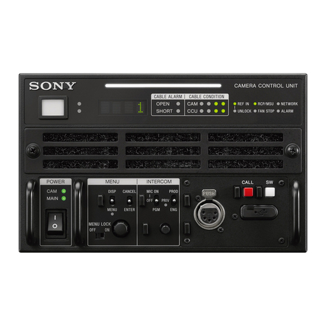
Sony CCU-TX7 User manual

CAMERA CONTROL UNIT
CCU-TX7
CCU-TX7P
CAMERA OPERATION UNIT
COU-TX7
SDI OUTPUT BOARD
DXBK-701
SERVICE MANUAL
Volume 1 1st Edition (Revised 2)

CCU-TX7 (E)/V1
!WARNING
This manual is intended for qualified service personnel only.
To reduce the risk of electric shock, fire or injury, do not perform any servicing other than that
contained in the operating instructions unless you are qualified to do so. Refer all servicing to
qualified service personnel.
!WARNUNG
Die Anleitung ist nur für qualifiziertes Fachpersonal bestimmt.
Alle Wartungsarbeiten dürfen nur von qualifiziertem Fachpersonal ausgeführt werden. Um die
Gefahr eines elektrischen Schlages, Feuergefahr und Verletzungen zu vermeiden, sind bei
Wartungsarbeiten strikt die Angaben in der Anleitung zu befolgen. Andere als die angegeben
Wartungsarbeiten dürfen nur von Personen ausgeführt werden, die eine spezielle Befähigung
dazu besitzen.
!AVERTISSEMENT
Ce manual est destiné uniquement aux personnes compétentes en charge de l’entretien. Afin
de réduire les risques de décharge électrique, d’incendie ou de blessure n’effectuer que les
réparations indiquées dans le mode d’emploi à moins d’être qualifié pour en effectuer d’autres.
Pour toute réparation faire appel à une personne compétente uniquement.

1
CCU-TX7 (E)/V1
MANUAL STRUCTURE
Purpose of this manual
Related manuals
This manual is the Service Manual Vol. 1 of the CAMERA CONTROL UNIT CCU-TX7
(for NTSC) and CCU-TX7P(for PAL), CAMERAOPERATION UNIT COU-TX7 and SDI
OUTPUT BOARD DXBK-701.
This manual contains the operation manual related to the operations of this equipment,
the replacement of the parts and adjustments.
In addition to this Service Manual Vol. 1, the following manual is provided.
..
..
.Service Manual Vol. 2
Part No. 9-977-286-23
Containssemiconductor pin assignments, parts lists, block diagrams, board illustrations
and schematic diagrams.


3
CCU-TX7 (E)/V1
TABLE OF CONTENTS
1. OPERATING INSTRUCTIONS
1-1. CCU-TX7/TX7P ............................................................................................ 1-1
1-2. DXBK-701 ...................................................................................................1-13
2. INSTALLATION
2-1. CONNECTORS AND CABLES ................................................................... 2-1
2-1-1. Connector Input/Output Signals .............................................................2-1
2-1-2. Connection Connector ............................................................................ 2-4
2-1-3. Wiring Diagram for Cable......................................................................2-4
2-2. MAKING OF WF MODE CONNECTOR .................................................... 2-4
2-3. COAX CONNECTOR ................................................................................... 2-5
2-4. OPERATING ENVIRONMENT ................................................................... 2-5
2-5. MOUNTING ON 19-INCH RACK ............................................................... 2-6
2-6. SWITCH FUNCTIONS ON BOARD ...........................................................2-7
3. SERVICE INFORMATION
3-1. BOARD LAYOUT.........................................................................................3-1
3-2. DISASSEMBLY/INSTALLATION OF MAIN PART .................................3-1
3-2-1. Removal of Cabinet ................................................................................ 3-1
3-2-2. Replacement of Switching Regulator ..................................................... 3-2
3-2-3. Replacement of Fan ................................................................................ 3-3
3-2-4. Removal of COU-TX7 ........................................................................... 3-3
3-3. CIRCUIT DESCRIPTION ............................................................................. 3-4
CT-181 board ....................................................................................................... 3-4
AA-90 board ........................................................................................................ 3-4
YD-26 board ........................................................................................................ 3-4
ES-20 board..........................................................................................................3-4
AU-234 board ...................................................................................................... 3-4
IO-140 board ........................................................................................................ 3-4
SDI-44 board (DXBK-701) ................................................................................. 3-4
3-4. EXTENSION OF DXBK-701 (SDI-44 BOARD) ......................................... 3-5
4. ADJUSTMENT
4-1. PREPARATION ............................................................................................ 4-1
4-1-1. Equipment Required ............................................................................... 4-1
4-1-2. Fixture.....................................................................................................4-1
4-1-3. Notes on Adjustment ..............................................................................4-1
4-1-4. Switch settings........................................................................................4-1
4-1-5. Connections ............................................................................................ 4-2
4-2. VIDEO SIGNAL SYSTEM ADJUSTMENT ................................................ 4-3
4-2-1. Sub-carrier Frequency Check .................................................................4-3
4-2-2. CAM H Phase Adjustment .....................................................................4-3
4-2-3. H Phase Adjustment ............................................................................... 4-4

4CCU-TX7 (E)/V1
4-2-4. SYNC Phase Adjustment ....................................................................... 4-4
4-2-5. INT SC Phase Adjustment......................................................................4-5
4-2-6. Y CLAMP Adjustment........................................................................... 4-5
4-2-7. Y OUT (COMP) Level Adjustment ....................................................... 4-6
4-2-8. Y OUT (VBS) Level Adjustment..........................................................4-6
4-2-9. R-Y/B-Y White Black Balance Adjustment...........................................4-7
4-2-10. G Level Adjustment ............................................................................... 4-7
4-2-11. R Level Adjustment................................................................................ 4-8
4-2-12. B Level Adjustment................................................................................ 4-8
4-2-13. WF OUT R/B DC OFFSET Adjustment................................................ 4-9
4-2-14. Carrier Balance Adjustment ................................................................... 4-9
4-2-15. Color Vector Adjustment ..................................................................... 4-10
4-2-16. R-Y/B-Y OUT Level Adjustment ........................................................4-10
4-2-17. VBS OUT Level Adjustment ...............................................................4-11
4-2-18. STAIR CASE Adjustment....................................................................4-11
4-2-19. WIDE ID Level Adjustment................................................................. 4-12
4-3. Y CABLE COMPENSATION SYSTEM ADJUSTMENT......................... 4-13
4-3-1. SYNC SEP Adjustment........................................................................4-13
4-3-2. BLACK Pulse Width Adjustment ........................................................ 4-13
4-3-3. SYNC Sample Hold Pulse Width Adjustment .....................................4-14
4-3-4. 22.5 MHz VCO DC Set Adjustment ....................................................4-14
4-3-5. Sample Pulse Width Adjustment.......................................................... 4-15
4-3-6. Sample Pulse V Gate Width Adjustment .............................................4-15
4-3-7. 22.5 MHz Carrier Level Adjustment.................................................... 4-16
4-3-8. Y DEMOD Carrier Balance Adjustment.............................................. 4-16
4-3-9. Y OFFSET Adjustment ........................................................................4-17
4-3-10. Y 90˚ Adjustment ................................................................................. 4-17
4-3-11. Y 1st AGC Adjustment ........................................................................ 4-17
4-3-12. Y Output Level Adjustment .................................................................4-18
4-4. CHROMA CABLE COMPENSATION SYSTEM ADJUSTMENT ..........4-18
4-4-1. 45 MHz Carrier Level Adjustment....................................................... 4-18
4-4-2. C PLL Set Adjustment..........................................................................4-19
4-4-3. B-Y DEMOD Carrier Balance Adjustment.......................................... 4-19
4-4-4. B-Y Crosstalk Adjustment ................................................................... 4-20
4-4-5. C 1st AGC Adjustment......................................................................... 4-20
4-4-6. B-Y OUT Level Adjustment ................................................................ 4-21
4-4-7. R-Y DEMOD Carrier Balance Adjustment.......................................... 4-21
4-4-8. R-Y Crosstalk Adjustment ................................................................... 4-22
4-4-9. R-Y OUT Level Adjustment ................................................................ 4-22
4-5. RETURN VIDEO CABLE COMPENSATION SYSTEM
ADJUSTMENT............................................................................................4-23
4-5-1. Return Video Carrier Frequency Adjustment.......................................4-23
4-5-2. Return Video Deviation Adjustment ....................................................4-23
4-6. PROMPT VIDEO CABLE COMPENSATION SYSTEM
ADJUSTMENT............................................................................................4-24
4-6-1. TX PROMPT VIDEO Demodulation Adjustment............................... 4-24
4-6-2. RX PROMPT VIDEO Demod. Adjustment......................................... 4-25
4-6-3. RX PROMPT VIDEO RF AGC Adjustment .......................................4-26
4-6-4. RX PROMPT VIDEO Level Adjustment ............................................4-27

5
CCU-TX7 (E)/V1
4-7. TRIAX INTERFACE SYSTEM ADJUSTMENT.......................................4-27
4-7-1. Frequency Set Adjustment ................................................................... 4-27
4-7-2. INCOM Deviation Adjustment ............................................................4-28
4-7-3. PGM Deviation Adjustment .................................................................4-28
4-7-4. INCOM Demodulation Adjustment ..................................................... 4-29
4-7-5. INCOM Level Adjustment ...................................................................4-29
4-7-6. MIC 1 Demodulation Adjustment ........................................................4-30
4-7-7. MIC 1 Level Adjustment......................................................................4-30
4-7-8. MIC 2 Demodulation Adjustment ........................................................4-31
4-7-9. MIC 2 Level Adjustment......................................................................4-31
4-7-10. CAM DATA Demodulation Adjustment .............................................4-32
4-7-11. CAM TONE Adjustment...................................................................... 4-32


1-1
CCU-TX7 (E)/V1
1997 by Sony Corporation
Operating Instructions
Before operating the unit, please read this manual
thoroughly and retain it for future reference.
Camera Control
Unit
3-859-845-12(1)
CCU-TX7/TX7P
SECTION 1
OPERATING INSTRUCTIONS
1-1. CCU-TX7/TX7P

1-2 CCU-TX7 (E)/V1
3
Table of Contents
Overview ............................................................................ 4
Product Features .................................................................. 4
Connections ......................................................................... 5
Installing the Camera Operation Unit ................................. 7
Location and Function of Parts ....................................... 8
Front Panel .......................................................................... 8
Rear Panel ......................................................................... 14
Internal Board Switches and Knobs .................................. 17
Notes on Use ................................................................... 20
Specifications .................................................................. 21
WARNING
To prevent fire or shock hazard, do not
expose the unit to rain or moisture.
This symbol is intended to alert the user to the
presence of uninsulated “dangerous voltage”
within the product’s enclosure that may be of
sufficient magnitude to constitute a risk of
electric shock to persons.
This symbol is intended to alert the user to the
presence of important operating and
maintenance (servicing) instructions in the
literature accompanying the appliance.
Owner’s Record
The model and serial numbers are located at the rear.
Record the serial number in the space provided below.
Refer to these numbers whenever you call upon your Sony
dealer regarding this product.
Model No. Serial No.
For the customers in the USA
This equipment has been tested and found to comply with
the limits for a Class A digital device, pursuant to Part 15 of
the FCC Rules. These limits are designed to provide
reasonable protection against harmful interference when the
equipment is operated in a commercial environment. This
equipment generates, uses, and can radiate radio frequency
energy and, if not installed and used in accordance with the
instruction manual, may cause harmful interference to radio
communications. Operation of this equipment in a residential
area is likely to cause harmful interference in which case the
user will be required to correct the interference at his own
expense.
You are cautioned that any changes or modifications not
expressly approved in this manual could void your authority
to operate this equipment.
This device requires shielded interface cables to comply with
FCC emission limits.
2

1-3
CCU-TX7 (E)/V1
5
When using one CCU-TX7/TX7P unit
Connections
Examples of how to connect other devices to this unit
are shown in the following.
Notes
•Be sure to power the CCU-TX7/TX7P off before
inserting or removing the triaxial cable connector.
•Some of the video camera’s switches and buttons
may not operate while the CCU-TX7/TX7P is
connected to it.
For details, see the operation instructions for the video
camera or camera adaptor.
SYNC AC IN
WFPIX
MIC
OUT
RETURN
VIDEO
PROMPT
VIDEO
DC IN
GENLOCK
INTERCOM
CCU/CAMERA
VIDEO
IN
REF
IN
INTERCOM/
TALLY VBS
VIDEO
IN
CAMERA
REMOTE
Y/R–Y/B–Y,
R/G/B,Y/C
1)
Control console
Out
In
In
In
In/Out
Headset
CA-TX7/TX7P
DXC-D30/D30P
Triaxial cable
CCA-7 cable
RCP-TX7
CCU-TX7/TX7P
3)
(front panel)
Reference sync signal
Teleprompter signal
DC power
source
2)
AC power source
2)
AC power cord
(supplied)
Video monitor Waveform monitor
1) Y/R–Y/B–Y, R/G/B, and Y/C outputs are switchable.
2) Use either AC or DC power source.
3) This illustration shows the CCU-TX7.
Headset
4
Overview
Overview
Pr oduct Features
The CCU-TX7/TX7P is a camera control unit that
connects to DXC-637 Series and DXC-D30 Series
Color Video Cameras via the CA-TX7/TX7P Camera
Adaptor.
This product’s features are described below.
Full-featured signal transfer functions
•The CCU-TX7/TX7P is able to transfer wideband
component video signals. (Y signals at 9 MHz or
above, and R–Y and B–Y signals at 4.5 MHz or
above)
•When using a triaxial cable, audio signals can be
transferred up to 750 meters (2461 feet) (when cable
diameter is 8.5 mm (
11
/
32
inch)) or 1,500 meters (4921
feet) (when cable diameter is 14.5 mm (
19
/
32
inch)).
•Transfer functions are provided for the following
signals.
Return video, teleprompter signal, microphone audio,
program audio, red tally and green tally signals
•An intercom switch is also provided.
Flexibly adaptable camera control functions
•The optional COU-TX7 Camera Operation Unit,
which can be installed on the CCU-TX7/TX7P’s
front panel, enables video camera operations to be
controlled from the CCU-TX7/TX7P.
•When several CCU-TX7/TX7P units are connected in
parallel, the optional RCP-TX7 Remote Control
Panel can be used to control video camera operations
as well as the color balance between cameras.
•An RS-232C connector is provided for the CCU-
TX7/TX7P, allowing a personal computer to be
connected for computer-based control of video
camera operations.
Wide array of input/output signals
The input and output connectors provided for the
CCU-TX7/TX7P include those for outputting such
signals as a composite video signal (VBS), component
video signals (switchable to RGB), SDI signals, and
video signals for video and waveform monitors, for
inputting a reference signal for external
synchronization.
Rack mountable
Two CCU-TX7/TX7P units can be installed side by
side in the optional RMM-TXC7 Rack Mount Bracket.

1-4 CCU-TX7 (E)/V1
7
Installing the Camera Operation Unit
The following describes how to fit the optional COU-
TX7 Camera Operation Unit to the CCU-TX7/TX7P’s
front panel.
1
Open the CCU-TX7/TX7P’s
front panel.
2
Remove the blank panel and
the connector cap.
3
Attach the camera operation
unit to the front panel and
connect the flat cable to the
connector.
4
Close the front panel and
fasten the screws.
Stopper
Connector cap
Blank panel
Flat cable
Camera
operation unit
6
Overview
VBS
VBS
REMOTE
REMOTE
CAMERA
CAMERA
GENLOCK
CCU/CAMERA
CCU/CAMERA
RS232C
RS232C
GEN
LOCK
RETURN
VIDEO
PROMPT
VIDEO
RETURN
VIDEO
PROMPT
VIDEO
Y/R–Y/B–Y,R/G/B,Y/C
Y/R–Y/B–Y,R/G/B,Y/C
1)
AC IN
DC IN
SDI
OUT
1)
4)
GENLOCK
RETURN VIDEO
PROMPT VIDEO
When using two CCU-TX7/TX7P units
CA-TX7/TX7P
DXC-D30/D30P
Triaxial cable
CCA-7 cable
RCP-TX7
CCU-TX7/TX7P
3)
Switcher, video
monitor, etc.
VCR
Chroma keyer
Reference sync signal
Return video signal
Teleprompter signal
(For power sources,
see the connections
illustrated for the unit
shown below.)
DC power
source
2)
AC power source
2)
AC power cord
(supplied)
Personal computer
(When the RCP-TX7s are
not connected.)
1) Y/R–Y/B–Y, R/G/B, and Y/C outputs are switchable.
2) Use either AC or DC power source.
3) This illustration shows the CCU-TX7.
4) Using the SDI OUT connectors requires the optional
DXBK-701 board.
Switcher, video
monitor, etc.
VCR
Chroma keyer
CCU-TX7/
TX7P
3)
CA-TX7/TX7P
DXC-D30/D30P
CCA-7 cable
Triaxial cable
RCP-TX7 Monitor with SDI input
VCR with SDI input
Waveform monitor
with SDI input
Switcher with SDI input

1-5
CCU-TX7 (E)/V1
9
CCU-TX7/TX7P switches and knobs
1TALLY lamp
The lamp lights red when a red tally signal is received
and green when a green tally signal is received.
It also lights red when the CALL button is pressed on
the CA-TX7/TX7P Camera Adaptor or RCP-TX7
Remote Control Panel connected to this unit.
The camera number plate (provided) can be attached to
this lamp.
2CABLE ALARM indicator
SHORT: this indicator lights when an overcurrent
occurs in the triaxial cable connected to the
CAMERA connector on the rear panel.
OPEN: this indicator lights when there is no triaxial
cable connected to the CAMERA connector on
the rear panel or when the current flowing in the
connected triaxial cable is excessively small.
3CALL button
When you press this button, it lights along with the red
TALLY lamps and CALL buttons on the video
camera, camera adaptor, and remote control panel
connected to this unit. This function can be used to call
the video camera or remote control panel operator.
You can then talk with the operator via the intercom.
This button also lights when the CALL button is
pressed on the camera adaptor or remote control panel.
4INTERCOM audio input/output and setting
section
INTERCOM connector (XLR 5-pin): Use this to
connect a headset.
INTERCOM (intercom level) knob: Use this to
adjust the intercom sound volume.
PGM (program audio level) knob: Use this to
adjust the sound volume when monitoring
program audio via a headset.
MIC switch: Use this switch to turn the headset’s
microphone ON or OFF.
LINE switch: Use this switch to select the channel
for intercom signals that are input and output via
the INTERCOM connector.
•CH1: Connects to channel 1
•CH2: Connects to channel 2
•PRIV: Does not connect to channel 1 or
channel 2. Instead, the intercom operates only
between this unit and the connected video
camera.
5CAMERA POWER switch and indicator
When the POWER switch is on, use this switch to
switch the power on and off to the video camera and
camera adaptor connected to this unit. The indicator
lights when this switch is turned on powering the
camera adaptor.
6POWER switch and indicator
This switches the power to this unit on or off. The
indicator lights when the power is on.
A
A
1
1
TALLY
POWER
CABLE ALARM
INTERCOMCAMERA
POWER
SHORT
CALL
ON
MIC
ON
OFF
INTERCOM
LINE
CH1
CH2
PGM
PRIV
OFF
OPEN
PUSH
1TALLY lamp
2CABLE ALARM indicator
3CALL button
4INTERCOM audio input/
output and setting section
5CAMERA POWER switch
and indicator
6POWER switch and
indicator
INTERCOM
MIC
ON
OFF
INTERCOM
LINE
CH1
CH2
PGM
PRIV
PUSH
MIC switch
LINE switch
PGM knob
INTERCOM knob
INTERCOM connector
8
Location and Function of Parts
Various switches, adjustment knobs, and connectors
are located on the front panel, rear panel, and also on
the edges of internal boards.
Location and Function of Parts
Front P anel
From the front panel, you can operate the CCU-TX7/
TX7P’s switches and knobs as well as the camera
operation unit’s switches and knobs (when the optional
COU-TX7 Camera Operation Unit has been installed).
For description of how to install the camera operation unit,
see “Installing the Camera Operation Unit” (page 7).
TALLY
SHUTTER
KNEE IRIS
WHITE/BLACK BALANCE
OUTPUT
M.GAMMA
GAIN TLCS
DETAIL
OPERATE
POWER
CABLE ALARM
INTERCOMCAMERA
POWER
SKIN
DETAIL
MASTER
BLACK
SHORT
CALL
ON
MIC
ON
OFF
INTERCOM
LINE
CH1
CH2
PGM
PRIV
OFF
OPEN
LOCK
PART
FULL
HIGH
MID
LOW
CAM
BARS
ON
Hz
OFF
ON
C.SCAN
AUTO
MANUAL
AUTO
PRESET
WHITE
BLACK
BLACK WHITE
AUTO ATW
MANUAL
AUTO
MANUAL
OFF
PRE
PUSH
CCU-TX7/TX7P switches and knobs
(see page 9) Camera operation unit switches and knobs
(see page 10)

1-6 CCU-TX7 (E)/V1
11
3SHUTTER setting section
SHUTTER switch: Use this switch to select a
shutter setting. This switch does not function
when the TLCS switch is on.
•C. SCAN: This activates the clear scan function.
•ON: This activates the normal shutter function.
•OFF: This turns off the shutter.
$button and 4button: When the SHUTTER
switch is set to either C. SCAN or ON, pressing
one of these buttons changes the shutter speed or
clear scan frequency as described below.
•When SHUTTER switch is set to C. SCAN
Pressing and holding one of these buttons
gradually reduces ($button) or increases (4
button) the clear scan frequency.
•When SHUTTER switch is set to ON
Each time one of these buttons is pressed, the
shutter speed is reduced ($button) or increased
(4button) by one step.
If you press both of these buttons at once, it
resets the clear scan frequency or shutter speed
(depending on the SHUTTER switch’s position)
to their factory settings.
Display: This displays the clear scan frequency
when the SHUTTER switch is set to C. SCAN or
the shutter speed when it is set to ON. “OFF”is
displayed here when the SHUTTER switch is set
to the OFF position.
When the TLCS switch is on, the display is blank.
SHUTTER
Hz
ON
C.SCAN
OFF
Display
SHUTTER switch
$button and 4button
4WHITE/BLACK BALANCE control section
BLACK AUTO/MANUAL switch
Use this switch to select whether to automatically
(AUTO) or manually (MANUAL) adjust the black
balance.
(When a DXC-637 series video camera is connected,
this switch is invalid and the black balance mode is
determined by the position of the WHITE AUTO/PRE/
MANUAL switch.)
WHITE/BLACK (white/black balance
adjustment) switch and indicators
When the WHITE AUTO/PRE/MANUAL switch is
set to AUTO, press this switch to the WHITE position
to automatically adjust the white balance.
When the BLACK AUTO/MANUAL switch is set to
AUTO, press this switch to the BLACK position to
automatically adjust the black balance.
The indicator by the WHITE or BLACK position
blinks at a one-second interval while the white balance
or black balance is being automatically adjusted. When
the automatic adjustment is completed, it stays lit for
about ten seconds, then goes out. If the automatic
adjustment fails, it blinks at a half-second interval for
about ten seconds and then goes out.
WHITE/BLACK BALANCE
AUTO
MANUAL
WHITE
BLACK
BLACK WHITE
AUTO ATW
MANUAL
PRE
WHITE/BLACK switch and
indicators
WHITE AUTO/PRE/MANUAL switch
ATW button
BLACK knob
(red) WHITE knob
(red)
BLACK knob
(blue)
WHITE knob
(blue)
BLACK AUTO/
MANUAL
switch
10
Location and Function of Parts
Camera operation unit switches and knobs
SHUTTER
KNEE IRIS
WHITE/BLACK BALANCE
OUTPUT
M.GAMMA
GAIN TLCS
DETAIL
OPERATE
SKIN
DETAIL
MASTER
BLACK
LOCK
PART
FULL
HIGH
MID
LOW
CAM
BARS
ON
Hz
OFF
ON
C.SCAN
AUTO
MANUAL
AUTO
PRESET
WHITE
BLACK
BLACK WHITE
AUTO ATW
MANUAL
AUTO
MANUAL
OFF
PRE
ON
1234
7GAIN switch
8TLCS switch
9M. GAMMA knob
0SKIN DETAIL switch
!¡ DETAIL knob
!£ DIP switch
!™ IRIS control section
1OUTPUT switch
2OPERATE switch
3SHUTTER setting
section
4WHITE/BLACK BALANCE
control section
5KNEE switch
6MASTER BLACK knob
The camera operation unit’s switches and knobs are
used to set and adjust video camera functions.
For details about the video camera functions and settings,
refer to operating instructions for your video camera.
1OUTPUT switch
Use this switch to select the video to be output from
this unit.
CAM: Image being shot via video camera
BARS: Color bars generated by this unit
2OPERATE (operation range setting) switch
Use this switch to set the operation range of the
camera operation unit.
LOCK: This setting disables all of the camera
operation unit’s functions.
PART: This setting enables only the IRIS control
section and MASTER BLACK knob to be
operated.
FULL: This setting enables all of the camera
operation unit’s functions to be used. Settings
changed while this switch was set to LOCK
become valid when this switch is set to FULL.

1-7
CCU-TX7 (E)/V1
13
!™ IRIS control section
IRIS AUTO/MANUAL switch
Use this switch to select between AUTO and
MANUAL iris adjustment modes. Be sure that the
IRIS switch on the video camera is set to AUTO.
AUTO: Iris is automatically adjusted.
MANUAL: Iris is adjusted with the iris adjustment
knob.
Iris adjustment knob
When the IRIS AUTO/MANUAL switch is set to
MANUAL, this knob can be used to manually adjust
the iris.
When the IRIS AUTO/MANUAL switch is set to
AUTO, this knob can be used to manually fine-tune
the automatic iris adjustment.
IRIS
AUTO
MANUAL
IRIS AUTO/MANUAL switch
Iris adjustment knob
!£ DIP switch
Use the four switches numbered 1 to 4 to make the
following settings.
No.1 OFF/No.2 OFF Standard color matrix setting
(This setting has no effect when a
DXC-D30 series video camera is
connected.)
No.1 ON/No.2 OFF
No.1 OFF/No.2 ON
Color matrix set for fluorescent
lighting (FL).
(This setting has no effect when a
DXC-D30 series video camera is
connected.)
No.1 ON/No.2 ON Color matrix set for color emphasis
(H.SAT).
(This setting has no effect when a
DXC-D30 series video camera is
connected.)
No.3 ON EVS function set on for the shutter.
(Has priority over the SHUTTER
switch setting on the camera
operation unit.)
No.4 ON Date and time display set on for the
output picture.
12
Location and Function of Parts
WHITE AUTO/PRE/MANUAL (white balance
auto/preset/manual) switch
Use this switch to select the white balance adjustment
mode. This switch does not function while the ATW
function is being used (while the ATW button is lit).
AUTO: This sets auto adjustment mode. It enables
the white balance to be automatically adjusted
using the WHITE/BLACK switch.
(When a DXC-637 series video camera is
connected: this also sets auto adjustment mode
for the black balance. The black balance can be
automatically adjusted even while the ATW
function is being used.)
PRE: This sets preset mode. The white balance is
maintained at the preset value.
(When a DXC-637 series video camera is
connected: this also sets auto adjustment mode
for the black balance. The black balance can be
automatically adjusted even while the ATW
function is being used.)
MANUAL: Sets manual adjustment mode. It
enables the white balance to be manually adjusted
using the WHITE knob (red) and WHITE knob
(blue).
(When a DXC-637 series video camera is
connected: this also sets manual adjustment mode
for the black balance. The black balance can be
adjusted manually even while the ATW function
is being used.)
ATW (auto tracing white balance) button
Press this button (which lights up when pressed) to
have the white balance adjusted automatically when
lighting conditions change.
BLACK (black balance) knob (red)
When the BLACK AUTO/MANUAL switch is set to
MANUAL, this knob can be used to adjust the black
level of the R signal.
BLACK (black balance) knob (blue)
When the BLACK AUTO/MANUAL switch is set to
MANUAL, this knob can be used to adjust the black
level of the B signal.
WHITE (white balance) knob (red)
When the WHITE AUTO/PRE/MANUAL switch is
set to MANUAL, this knob can be used to adjust the
gain of the R signal.
WHITE (white balance) knob (blue)
When the WHITE AUTO/PRE/MANUAL switch is
set to MANUAL, this knob can be used to adjust the
gain of the B signal.
5KNEE switch
Use this switch to adjust the knee setting.
AUTO: Knee is automatically adjusted
PRESET: Knee is adjusted to preset value
6MASTER BLACK knob
This adjusts the master black (master pedestal level)
setting. The click position of the knob provides a
typical setting.
7GAIN switch
Use this switch to set any of three video amp gain
levels (HIGH, MID, or LOW). The gain value
corresponding to these levels can be set using a menu
on the video camera.
8TLCS (total level control system) switch
Press this switch to turn the total level control system
on or off. The switch lights when it is turned on. When
this switch is on, settings made with the GAIN switch
and SHUTTER switch are ignored.
(This function cannot be used when a DXC-637 series
video camera is connected.)
9M. GAMMA (master gamma) knob
Use this knob to adjust the gamma curve. The click
position of the knob provides a typical setting.
(This function cannot be used when a DXC-637 series
video camera is connected.)
0SKIN DETAIL switch
Use this switch to turn the skin detail correction
function on or off.
(This function cannot be used when a DXC-637 series
video camera is connected.)
!¡ DETAIL knob
Use this knob to adjust the detail level. The click
position of the know proides a typical setting.

1-8 CCU-TX7 (E)/V1
14
Location and Function of Parts
Rear Panel
1PGM IN (program audio input) connector (XLR
3-pin)
The program audio signal is input via this connector.
2CAMERA connector (triaxial)
Connect a triaxial cable here to connect this unit to the
CA-TX7/TX7P Camera Adaptor attached to a video
camera.
3RTS (intercom) connector (XLR 3-pin)
Use this connector to connect an RTS intercom system
or a Clear-Com intercom system.
Contact a Sony dealer before using this connector.
4COAX (coaxial) connector (BNC type)
Use this connector for input and output of signals from
the video camera connected via a coaxial cable. No
power is supplied to the video camera or camera
adaptor via the coaxial cable.
CAMERA
COAX
VBS1 R/R-Y/C
GENLOCK
PROMPTVIDEO
DC IN
AC IN
RETURNVIDEO
VBS2
PIX
12
G/Y/Y
12
B/B-Y
12
WF SYNC SPARE
REMOTE WF MODE
BREAKER
INTERCOM/TALLY
CH1
CH1
12
CH2
SDI
OUT
RS232C CH2
PGM IN
RTS
INPUT
OUTPUT
MIC OUT
75Ω
ON
OFF
75Ω
ON
OFF
75Ω
ON
OFF
75Ω
ON
OFF
1
2
9OUTPUT connectors
!¡ INPUT connectors
and 75 Ωtermination
switches
!£ DC IN connector
!™ MIC OUT connectors
!∞AC IN connector
!§ Breaker switch
1PGM IN connector
2CAMERA connector
3RTS connector
4COAX connector
5REMOTE connector
6WF MODE connector
7INTERCOM/TALLY
connector
8RS232C connectors
Internal board settings must be changed before using this
connector. For details, contact a Sony dealer.
5REMOTE (remote control panel) connector (10-
pin)
Use this connector to connect the RCP-TX7 Remote
Control Panel via a CCA-7 cable.
6WF MODE (waveform monitor mode)
connector (4-pin)
Connect to the corresponding connector on a
waveform monitor when monitoring signals in
sequential mode.
Internal board settings must be changed before using this
connector. For details, contact a Sony dealer.
7INTERCOM/TALLY connector (D-sub 25-pin)
Intercom signals and tally signals are input and output
via this connector. Connect to the intercom system’s
INTERCOM/TALLY connector.
!º Fan
!¢ SDI OUT connectors
Illustration: CCU-TX7
15
8RS232C connectors (D-sub 25-pin)
There are two connectors, CH1 and CH2. You can use
these connectors to connect a personal computer to
control the video camera.
You may also use these connectors to connect this unit
to another CCU-TX7/TX7P unit. It is possible to carry
out color balancing or linked iris adjustment between
two or more interconnected CCU-TX7/TX7P units
using the RCP-TX7 Remote Control Panel.
For details, refer to the operating instructions for the RCP-
TX7.
9OUTPUT connectors (BNC type)
R/R–Y/C, G/Y/Y, and B/B–Y (component video
signal/RGB signal/Y and C signal output)
connectors
Use these connectors to output the signals from the
video camera as component signals (R–Y, B–Y, and
Y), RGB signals for chroma keying, or Y and C
signals. Use a switch on an internal board (ES-20) to
select the type of output signal.
VBS1 and VBS2 (composite video signal 1 and
2 output) connectors
Use these connectors to output signals from a video
camera as composite video signals.
SYNC (sync signal output) connector
This connector outputs a SYNC signal (0.3 Vp-p, 75
Ω). Connect to the synchronization signal input
connector on a waveform monitor or video monitor.
PIX (picture monitor output) connector
Use this connector to output a video signal to a video
monitor. Use the MONITOR SELECT button on the
RCP-TX7 Remote Control Panel to set the type of
signal to be output. Selection of the signal type also
applies to the output from the WF connector.
VBS1
R/R-Y/C
VBS2
PIX
12
G/Y/Y
12
B/B-Y
12
WF SYNC SPARE
OUTPUT
PIX connector
WF connector
SPARE connector
SYNC connector
R/R–Y/C, G/Y/Y, and B/B–Y connectors
VBS1 and VBS2 connectors
WF (waveform monitor output) connector
Use this connector to output a video signal to a
waveform monitor. Use the MONITOR SELECT
button on the RCP-TX7 Remote Control Panel to set
the type of signal to be output. Selection of the signal
type also applies to the output from the PIX connector.
SPARE connector
This connector is not used (it is reserved for future
use).
0Fan
Acoolingfanisbuiltin.
Note
If the fan should fail, the CAMERA POWER indicator
flashes. Immediately switch off the power, and consult
your supplier Sony dealer for repair. Continuing to use
the unit when the fan is defective may shorten the life
of the equipment.
!¡ INPUT connectors (BNC type) and 75-Ω
termination switches
This section includes four pairs of loop-through
connectors and corresponding 75-Ωtermination
switches.
GENLOCK (generator lock) connectors
Use these connectors to input a reference sync signal
(black burst signal or composite video signal) for
external synchronization .
RETURN VIDEO 1 and RETURN VIDEO 2
connectors
These connectors correspond to the RETURN 1 and
RETURN 2 buttons on the CA-TX7/TX7P Camera
Adaptor. Two sets of return video signals can be input
via these two pairs of connectors.
GENLOCK
PROMPTVIDEO
RETURNVIDEO
INPUT
75Ω
ON
OFF
75Ω
ON
OFF
75Ω
ON
OFF
75Ω
ON
OFF
1
2
GENLOCK connectors
RETURN VIDEO 1 and
RETURN VIDEO 2 connectors
PROMPT VIDEO connectors
75-Ωtermination switches

1-9
CCU-TX7 (E)/V1
17
CT-181 AA-90 YD-26 ES-20
SDI-44
Internal Board Switches and Knobs
Loosen the two screws on the right side of the front
panel to expose switches and knobs on the edges of
internal boards.
For details concerning adjustment of internal board
switches and knobs, contact a Sony dealer.
1ES-20 board
2AA-90 board
3CT-181 board
Front panel screws
YD-26 board
SDI-44 board
(DXBK-701)
a)
a) The SDI-44 board is an option available as the DXBK-701. For details of installation
and operation, refer to the operating instructions supplied with the DXBK-701.
16
Location and Function of Parts
PROMPT VIDEO connectors
Use these connectors to input teleprompter signals.
75-Ωtermination switches
When only one loop-through connector is used and the
other connector in the pair is not connected to any
external device, set the corresponding 75-Ω
termination switch to the ON position.
!™ MIC OUT connectors (XLR 3-pin)
Use these connectors to output microphone signals
(CH1 and CH2) from the connected video camera.
!£ DC IN connector (XLR 4-pin)
Use this connector to operate this unit using a DC
power source (10.5 to 17 V).
!¢ SDI (serial digital interface) OUT connectors 1
and 2 (BNC type)
These output the signals from the video camera as SDI
signals. Connect them to a digital VCR, digital video
switcher, video monitor, or other device with an SDI
input connector. Using the SDI OUT connectors
requires the optional DXBK-701 board.
For details, refer to the operating instructions for the
DXBK-701.
!∞AC IN connector
Use this connector to connect an AC power source via
the supplied power cord. Use the supplied plug retainer
to attach the power cord to this unit.
!§ Breaker switch
If the input current exceeds 10 A during operation of
the unit on a DC power source, the breaker is actuated
to shut off the power supply. To resume operation,
push in the breaker switch after making sure the input
current does not exceed 10 A.

1-10 CCU-TX7 (E)/V1
19
INTERCOM (intercom system select) switches
Use these switches to select the type of external
intercom system to be used. Set the upper switch to
4W if no external intercom is connected.
If you set the upper switch to RTS, select either RTS
or CLEARCOM with the lower switch.
3CT-181 board
R TALLY (red tally) and G TALLY (green tally)
switches
Set these switches to CONTACT (to use contact
signals) or POWER (to use voltage signals) for the red
tally and green tally. If you set them to POWER, select
either DC24V or TTL.
MIC GAIN adjustment screws
Use these screws to adjust the microphone amplifier
gain for the camera adaptor. The standard level
(NORM) is 0 dB, and the gain setting can be adjusted
to any of 16 levels from –12 dB (MIX) to +12 dB.
Adjust the gain so that, on the AA-90 board, the green
and orange LEVEL IND indicators are lit while the
audio level is normal with the red indicator lighting
only when the maximum audio level is reached. If the
red indicator does not light at all, or if the orange
indicator lights only intermittently, raise the gain level.
If the red indicator stays lit, lower the gain.
CT-181
RTALLY
GTALLY
MIC GAIN
PANEL
CONTACT
POWER
DC24V
TTL
CONTACT
POWER
REMOTE
LOCAL
CONTROL MODE
NORMAL
SLAVE
DC24V
NORM
MIN
MAX
NORM
MIN
MAX
CH1
CH2
TTL
R TALLY and G TALLY
switches
MIC GAIN adjustment screws
PANEL switch
CONTROL MODE switch
PANEL (panel control) switch
When the COU-TX7 Camera Operation Unit has been
installed on this unit while the RCP-TX7 Remote
Control Panel is also connected to the unit, use this
switch to select the camera operation unit or the
remote control panel as the control device.
REMOTE: Enables the video camera to be
controlled from the remote control panel.
LOCAL: Disables remote control (via the remote
control panel) of the video camera.
CONTROL MODE switch
If another CCU-TX7/TX7P unit is connected to this
unit, use this switch to select whether the video camera
is controlled directly from this unit or from the other
CCU-TX7/TX7P unit.
NORMAL: Video camera is controlled directly from
this unit.
SLAVE: Video camera is controlled from other
CCU-TX7/TX7P unit.
This switch does not operate when the RCP-TX7
Remote Control Panel is connected to this unit. In this
case, use the remote control panel to make the above
selection.
18
Location and Function of Parts
1ES-20 board
H PHASE (horizontal phase) adjustment screw
Turn this screw with a screwdriver to adjust the
horizontal phase alignment between an external sync
signal and the output signal.
SC PHASE (subcarrier phase setting) switch
and fine-tuning screw
Use this switch and screw to adjust the output signal
subcarrier phase with respect to an external sync
signal. After setting the SC PHASE switch, turn the
fine-tuning screw to make fine adjustments.
OUTPUT 1 and OUTPUT 2 switches
Use these switches to select the type of signal to be
output via the OUTPUT connectors (R/R–Y/C, G/Y/Y,
B/B–Y). The OUTPUT 1 switch corresponds to the
three OUTPUT connectors on the left side and the
OUTPUT 2 switch to the three OUTPUT connectors
on the right side.
R/G/B: Selects output of R, G, and B signals from
the OUTPUT connectors.
Y/R–Y/B–Y: Selects output of R–Y, Y, and B–Y
component signals from the OUTPUT connectors.
Y/C: Selects output of Y and C signals from the
OUTPUT connectors.
2AA-90 board
PGM IN (program audio input level setting)
switch
Use this switch to set the program audio input level to
0 dB or –20 dB.
MIC 1 LEVEL and MIC 2 LEVEL switches
Use these switches to set the microphone output levels
for channel 1 (CH1) and channel 2 (CH2) to 0 dB or
–20 dB.
MIC TEST switch
Set this switch to CH1 or CH2 to mix that channel’s
microphone signals from the video camera with the
program audio, so that the mixed input can be
monitored via a headset connected to this unit or a
camera adaptor. This switch is used to check the
microphone signals.
LEVEL IND (microphone level) indicators
The transfer levels for microphone signals (CH1 and
CH2) are indicated by colors. The upper indicator
corresponds to channel 1 (CH1) and the lower one to
channel 2 (CH2).
Green: Approximately –12 dB to 0 dB
Orange: Approximately 0 dB to +12 dB
Red: Approximately +12 dB or higher
Use these indicators along with the MIC TEST switch
to check microphone signal lines or as a adjustment
indicator when adjusting the microphone gain with a
MIC GAIN adjustment screw on the CT-181 board.
ES-20
PHASE
OUTPUT 1
OUTPUT 2
H
SC
0
180
R/G/B
Y/R-Y/B-Y
Y/C
R/G/B
Y/R-Y/B-Y
Y/C
H PHASE adjustment screw
SC PHASE switch and fine-tuning screw
OUTPUT 1 and OUTPUT 2 switches
PGM IN switch
MIC 1 LEVEL and MIC 2 LEVEL
switches
MIC TEST switch
LEVEL IND indicators
INTERCOM switches
AA-90
PGM IN
LEVEL IND
INTERCOM
MIC 1 LEVEL
0dB
-20dB
0dB
-20dB
0dB
-20dB
RTS
CLEAR
COM
CLEAR
COM
CH1
CH2
OFF
2W
RTS
4W
MIC 2 LEVEL
MIC TEST

1-11
CCU-TX7 (E)/V1
21
Specifications
General
Power requirements
CCU-TX7: 120 VAC, 50/60 Hz
CCU-TX7P: 220 to 240 VAC, 50/
60 Hz, 0.45 A
10.5 to 17.0 VDC
Power consumption
95 W
Cable length 1500 m max. (diameter: 14.5 mm )
Operating temperature
5°C to 40°C (41°F to 104°F)
Mass About 8.45 kg (18 lb 10 oz)
Dimensions (w/h/d, excluding protruding parts)
200 ×164 ×370 mm (7
7
/
8
×6
1
/
2
×
14
5
/
8
inches)
Input connectors
GENLOCK BNC type (2, loop-through)
VBS/BS, 1.0Vp-p, 75 Ω
RETURN VIDEO 1, 2
BNC type (2 each, loop-through)
VBS, 1.0 Vp-p, 75 Ω
PROMPT VIDEO BNC type (2, loop-through)
VBS, 1.0 Vp-p, 75 Ω
PGM IN XLR 3-pin (1)
Output connectors
VBS1, VBS2 BNC type (1 each)
VBS, 1.0 Vp-p, 75 Ω
Y/R–Y/B–Y
1)
BNC type (2 each)
Y: 1.0 Vp-p, 75 Ω
R–Y/B–Y: 700 mVp-p (CCU-
TX7)/525 mVp-p (CCU-TX7P),
75 Ω
R/G/B
1)
BNC type (2 each)
700 mVp-p, 75 Ω
PIX BNC type (1), 1.0 Vp-p, 75 Ω
WF BNC type (1)
700 mVp-p, 75 Ω
Encoded output: 1.0 Vp-p, 75 Ω
WF MODE 4-pin (1)
MIC OUT XLR 3-pin (2)
0 dBu/–20 dBu balanced,
2 channels
Y/C
1)
BNC type (2 each)
Y: 1.0 Vp-p, 75 Ω
C: 286 mV (CCU-TX7)/300 mV
(CCU-TX7P) (burst), 75 Ω
SDI
2)
BNC type (2)
SDI format, 270 Mbps, SMPTE
259M (CCU-TX7)/CCIR656-III
(CCU-TX7P)
SYNC BNC type (1)
0.3 Vp-p, 75 Ω, negative polarity
Camera control input/output connectors
CAMERA Triaxial (1)
COAX BNC type (1)
REMOTE 10-pin (1)
INTERCOM/TALLY
D-sub 25-pin (1)
4W/2W
TALLY: 24 VDC, TTL level or
contact signals switchable
RTS XLR 3-pin (2)
RS232C D-sub 25-pin (2)
INTERCOM(on the front panel)
XLR 5-pin (1)
Accessories supplied
AC power cord (1)
Power cord plug retainer (1)
Number plates (1 set)
Operation Manual (1)
Optional accessories
COU-TX7 Camera Operation Unit
DXBK-701 SDI Output Board
RCP-TX7 Remote Control Panel
RMM-TXC7 Rack Mount Bracket
Design and specifications are subject to change
without notice.
1) Y/R–Y/B–Y, R/G/B, and Y/C outputs are switchable.
2) When the optional DXBK-701 is installed.
..........................................................................................................................................................................................................
20
Location and Function of Parts
Use and storage locations
Avoid using or storing the unit in the following places:
•Where it is subject to extremes of temperature
(operating temperature: 5°C to 40°C (41°F to
104°F)).
Note that in summer the temperature in a car with the
windows closed can reach 50°C (122°F).
•Very damp or dusty places.
•Where rain is likely to reach the unit.
•Places subject to severe vibration.
•Near strong magnetic fields
•Near transmitting stations generating strong radio
waves.
Avoid violent impacts
Dropping the unit, or otherwise imparting a violent
shock to it, is likely to cause it to malfunction.
Notes on Use
Do not cover with cloth
While the unit is in operation, do not cover it with a
cloth or other material. This can cause the temperature
to rise, leading to a malfunction.
After use
Turn the unit off.
Care
If the body of the unit is dirty, wipe it with a dry cloth.
For severe dirt, use a soft cloth steeped in a small
amount of neutral detergent, then wipe dry. Do not
use volatile solvents such as alcohol or thinners, as
these may damage the finish.

1-12 CCU-TX7 (E)/V1
CCU-TX7/TX7P
English
To switch the DXC-D30WS/D30WSP
aspect ratio
To switch the DXC-D30WS/D30WSP Digital Video
Camera connected to this unit via the CA-TX7/TX7P
Camera Adaptor between 16:9 and 4:3 aspect ratios,
use the following methods.
When using the RCP-TX7 Remote Control
Panel
Switch the aspect ratio using advanced setting page
9/11 of the RCP-TX7’s OTHERS menu.
When using the COU-TX7 Camera Operation
Unit
Switch the aspect ratio using the DXC-D30WS/
D30WSP’s advanced menu.
Wide-aspect ID signals
When using the DXC-D30WS/D30WSP connected
to this unit via the CA-TX7/TX7P with the 16:9
aspect ratio, wide-aspect ID signals
1)
are added to the
video signals
2)
output from this unit.
It is possible to change the internal board settings of
this unit so that the ID signals are not added to the
video signals.
For more information about this, consult your Sony
service representative.
1) Complying with EIAJ CPR-1204 (CCU-TX7) or ETS
WSS (CCU-TX7P).
2) •Composite video signals 1 and 2 (output from the
VBS1 and VBS2 connectors)
•Video signal for video monitors (output from the PIX
connector)
•Video signal for waveform monitors (output from the
WF connector)
•Component video Y signal (output from the Y
connector)
•Y signal of Y and C signal output (output from the Y
connector)
3-864-243-01(1)
English
Pin assignment of the INTERCOM/TALLY
connector
The pin assignment for the unit’s INTERCOM/
TALLY connector (D-sub 25-pin) is as follows.
No. Signal name Specifications
1 GREEN TALLY (Y) IN ON: 24V DC/TTL(H)/Short
OFF: 0V DC/TTL(L)/Open
14 GREEN TALLY (X) IN
2 RED TALLY (Y) IN ON: 24V DC/TTL(H)/Short
OFF: 0V DC/TTL(L)/Open
15 RED TALLY (X) IN
3 GND Ground for intercom remote
signal
16 CAM MIC OFF IN L: Camera intercom off
4 CH2 INT IN L: Channel-2 interrupt on
17 CH1 INT IN L: Channel-1 interrupt on
5 4W CH2 (R) (G) OUT 4-wire channel-2 system receive,
0 dBu balanced
18 4W CH2 (R) (Y) OUT
6 4W CH2 (R) (X) OUT
19 4W CH2 (T) (G) IN 4-wire channel-2 system talk,
0 dBu balanced
7 4W CH2 (T) (Y) IN
20 4W CH2 (T) (X) IN
8 2W CH2 (G) IN/OUT 2-wire channel-2 system,
0 dBu
Recommended termination
impedance: 600 ohms
21 2W CH2 (X) IN/OUT
9 4W CH1 (R) (G) OUT 4-wire channel-1 system receive,
0 dBu balanced
22 4W CH1 (R) (Y) OUT
10 4W CH1 (R) (X) OUT
23 4W CH1 (T) (G) IN 4-wire channel-1 system talk,
0 dBu balanced
11 4W CH1 (T) (Y) IN
24 4W CH1 (T) (X) IN
12 2W CH1 (G) IN/OUT 2-wire channel-1 system,
0 dBu
Recommended termination
impedance: 600 ohms
25 2W CH1 (X) IN/OUT
13 CHASSIS GND Chassis ground
0 dBu=0.775 Vrms
12345678913
141516171819202122232425
1112 10
Other manuals for CCU-TX7
2
This manual suits for next models
1
Table of contents
Other Sony Control Unit manuals
Popular Control Unit manuals by other brands

RADIKAL TECHNOLOGIES
RADIKAL TECHNOLOGIES Swarm Oscillator RT-311 quick start guide

Whelen Engineering Company
Whelen Engineering Company CenCom Core-R CEM4HC installation guide

TECSYSTEM
TECSYSTEM NT511Series instruction manual

Motorola
Motorola ACE3600 RTU owner's manual

Phason
Phason PEC Plus User manual and installation guide

TLV
TLV COS Series instruction manual