6Features
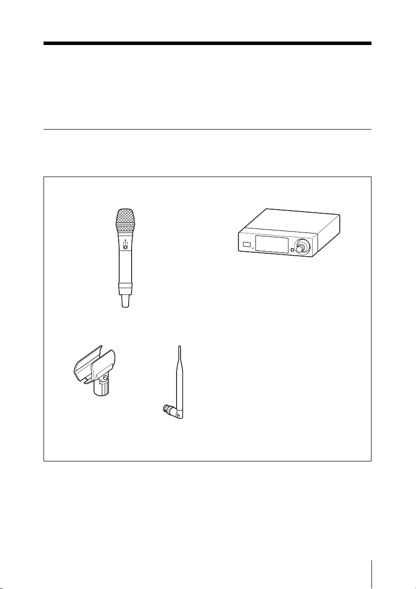
DWZ-M50
The DWZ-M50 is a package that includes a
handheld microphone (transmitter: ZTX-
M01) and a half-rack receiver (receiver:
ZRX-HR50) and is ideal for use with
vocals.
ZTX-M01
A microphone designed with a sturdy metal
body.
Equipped with a muting function and an
attenuator adjustment function, the unit
supports a wide range of audio input levels.
In addition, the interchangeable
microphone unit allows you to use the
microphone in a variety of applications.
* The microphone unit’s mounting area has a
diameter of 31.3 mm and a pitch of 1.0 mm.
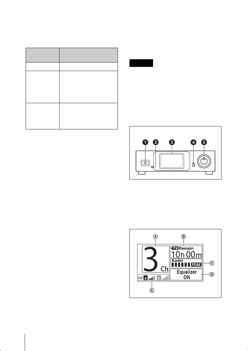
ZRX-HR50
A half-rack receiver equipped with large-
screen high-resolution color LCD that
combines high-functionality with simple
operability.
The Best Channel Selection and Clear
Channel Scan functions allow quick and
easy configuration of safe channels. The
cable tone generator also allows you to
match the quality of wireless and wired
audio. This reduces the amount of equalizer
adjustment necessary on the amp side
during wireless transmission. In addition,
the 5-band graphic equalizer allows wide-
range audio-quality adjustment. You can
also select whether the muting function
applies to the UNBALANCED/
BALANCED OUTPUT connector.
Using the optional RMM-HRD1 Rack
Mount Kit allows you to mount the unit on
a rack.
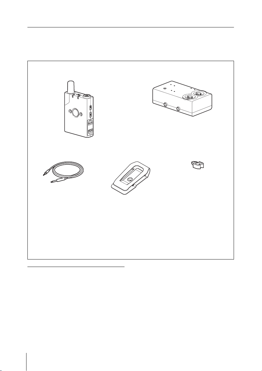
DWZ-B30GB
The DWZ-B30GB is a package that
includes a body-pack transmitter
(transmitter: ZTX-B01) and a compact
receiver (receiver: ZRX-C30) and is ideal
for use with electric guitars, electric
acoustic guitars, electric bass guitars, etc.
ZTX-B01
A transmitter designed with a sturdy metal
body.
Equipped with a muting function, an
instrument/mic input switching function,
and an attenuator adjustment function, the
unit supports a wide range of audio input
levels. The supplied belt clip can be rotated
in 90-degree increments, allowing you to
adjust the direction in which the cables
extend based on your environment.
ZRX-C30
A compact receiver equipped with an
internal antenna that is capable of
withstanding rough handling.
Power can be supplied by the supplied 12 V
AC adapter, by an external 9 V DC power
supply, or by a square 9 V dry cell battery
(6LR61). The unit supports power
distributors, allowing you to reduce noise
caused by battery operation. The cable tone
generator also allows you to match the
quality of wireless and wired audio. This
reduces the amount of equalizer adjustment
necessary on the amp side during wireless
transmission. The muting function does not
affect the TUNER OUT connector,
allowing tuning without sound output.