Sony UP25MD User manual

Color Video
Printer
Instructions for Use
Before operating the unit, please read this manual thoroughly
and retain it for future reference.
UP-25MD
4-162-900-13(1)
© 2010 Sony Corporation

2
Owner’s Record
The model and serial numbers are located at the rear.
Record these numbers in the space provided below.
Refer to these numbers whenever you call upon your Sony
dealer regarding this product.
Model No. ____________________
Serial No. ____________________
To reduce the risk of fire or electric shock, do not
expose this apparatus to rain or moisture.
To avoid electrical shock, do not open the
cabinet. Refer servicing to qualified personnel
only.
THIS APPARATUS MUST BE EARTHED.
To disconnect the main power, unplug the AC IN
connector.
For the customers in the U.S.A.
This equipment has been tested and found to comply with
the limits for a Class A digital device, pursuant to Part 15
of the FCC Rules. These limits are designed to provide
reasonable protection against harmful interference when
the equipment is operated in a commercial environment.
This equipment generates, uses, and can radiate radio
frequency energy and, if not installed and used in
accordance with the instruction manual, may cause
harmful interference to radio communications. Operation
of this equipment in a residential area is likely to cause
harmful interference in which case the user will be
required to correct the interference at his own expense.
You are cautioned that any changes or modifications not
expressly approved in this manual could void your
authority to operate this equipment.
All interface cables used to connect peripherals must be
shielded in order to comply with the limits for a digital
device pursuant to Subpart B of Part 15 of FCC Rules.
For the customers in Canada
This unit has been certified according to Standard CSA
C22.2 No.601.1.
For the customers in the U.S.A and Canada
When you use this product connected to 240 V single
phase, be sure to connect this product to a center tapped
circuit.
Important safeguards/notices for use in the
medical environments
1. All the equipments connected to this unit shall be
certified according to Standard IEC60601-1,
IEC60950-1, IEC60065 or other IEC/ISO Standards
applicable to the equipments.
2. Furthermore all configurations shall comply with the
system standard IEC60601-1-1. Everybody who
connects additional equipment to the signal input part
or signal output part configures a medical system, and
is therefore, responsible that the system complies with
the requirements of the system standard IEC60601-1-1.
If in doubt, consult the qualified service personnel.
3. The leakage current could increase when connected to
other equipment.
4. For this particular equipment, all accessory equipment
connected as noted above, must be connected to mains
via an additional isolation transformer conforming with
the construction requirements of IEC60601-1 and
providing at least Basic Insulation.
5. This equipment generates, uses, and can radiate radio
frequency energy. If it is not installed and used in
accordance with the instruction manual, it may cause
interference to other equipment. If this unit causes
interference (which can be determined by unplugging
the power cord from the unit), try these measures:
Relocate the unit with respect to the susceptible
equipment. Plug this unit and the susceptible
equipment into different branch circuit.
Consult your dealer. (According to standard IEC60601-1-
2 and CISPR11, Class B, Group 1)
WARNING
This symbol indicates the equipotential
terminal which brings the various parts of a
system to the same potential.
This symbol indicates the manufacturer, and
appears next to the manufacturer’s name and
address.
Refer to the operating instructions
Follow the directions in the operating
instructions for parts of the unit on which this
mark appears.

3
Important EMC notices for use in the medical environments
• The UP-25MD needs special precautions regarding
EMC and needs to be installed and put into service
according to the EMC information provided in this
instructions for use.
• The portable and mobile RF communications equipment
such as cellular phones can affect the UP-25MD.
Warning
The use of accessories and cables other than those
specified, with the exception of replacement parts sold by
Sony Corporation, may result in increased emissions or
decreased immunity of the UP-25MD.
Warning
If the UP-25MD should be used adjacent to or stacked with
other equipment, it should be observed to verify normal
operation in the configuration in which it will be used.
Guidance and manufacturer’s declaration-electromagnetic emissions
The UP-25MD is intended for use in the electromagnetic environment specified below.
The customer or the user of the UP-25MD should assure that it is used in such an environment.
Emission test Compliance Electromagnetic environment-guidance
RF emissions
CISPR 11
Group 1
The UP-25MD uses RF energy only for its internal function.
Therefore, its RF emissions are very low and are not likely
to cause any interference in nearby electronic equipment.
RF emissions
CISPR 11
Class B
The UP-25MD is suitable for use in all establishments,
including domestic establishments and those directly
connected to the public low-voltage power supply network
that supplies buildings used for domestic purposes.
Harmonic emissions
IEC 61000-3-2
Class A
Voltage fluctuations/
flicker emissions
IEC 61000-3-3
Complies

4
Guidance and manufacturer’s declaration - electromagnetic immunity
The UP-25MD is intended for use in the electromagnetic environment specified below. The customer or the user of the
UP-25MD should assure that it is used in such as environment.
Immunity test IEC 60601 test
level Compliance level Electromagnetic environment-guidance
Electrostatic
discharge (ESD)
IEC 61000-4-2
±6 kV contact
±8 kV air
±6 kV contact
±8 kV air
Floors should be wood, concrete or ceramic tile. If floors are
covered with synthetic material, the relative humidity should
be at least 30%.
Electrical fast
transient/burst
IEC 61000-4-4
±2 kV for power
supply lines
±1 kV for input/
output lines
±2 kV for power
supply lines
±1 kV for input/
output lines
Mains power quality should be that of a typical commercial or
hospital environment.
Surge
IEC 61000-4-5
±1 kV differential
mode
±2 kV common
mode
±1 kV differential
mode
±2 kV common
mode
Mains power quality should be that of a typical commercial or
hospital environment.
Voltage dips, short
interruptions and
voltage variations
on power supply
input lines
IEC 61000-4-11
< 5% UT
(> 95% dip in UT)
for 0.5 cycle
40% UT
(60% dip in UT)
for 5 cycles
70% UT
(30% dip in UT)
for 25 cycles
< 5% UT
(> 95% dip in UT)
for 5 sec
< 5% UT
(> 95% dip in UT)
for 0.5 cycle
40% UT
(60% dip in UT)
for 5 cycles
70% UT
(30% dip in UT)
for 25 cycles
< 5% UT
(> 95% dip in UT)
for 5 sec
Mains power quality should be that of a typical commercial or
hospital environment. If the user of the UP-25MD requires
continued operation during power mains interruptions, it is
recommended that the UP-25MD be powered from an
uninterruptible power supply or a battery.
Power frequency
(50/60 Hz)
magnetic field
IEC 61000-4-8
3 A/m 3 A/m Power frequency magnetic fields should be at least
characteristic of a typical location in a typical commercial or
hospital environment.
NOTE: UTis the a.c. mains voltage prior to application of the test level.

5
Guidance and manufacturer’s declaration - electromagnetic immunity
The UP-25MD is intended for use in the electromagnetic environment specified below. The customer or the user of the
UP-25MD should assure that it is used in such as environment.
Immunity test IEC 60601 test
level Compliance level Electromagnetic environment-guidance
Conducted RF
IEC 61000-4-6
Radiated RF
IEC 61000-4-3
3 Vrms
150 kHz to 80 MHz
3 V/m
80 MHz to 2.5 GHz
3 Vrms
3 V/m
Portable and mobile RF communications equipment should
be used no closer to any part of the UP-25MD, including
cables, than the recommended separation distance
calculated from the equation appliance to the frequency of
the transmitter.
Recommended separation distance
d= 1.2 √P
d= 1.2 √P80 MHz to 800 MHz
d= 2.3 √P800 MHz to 2.5 GHz
Where Pis the maximum output power rating of the
transmitter in watts (W) according to the transmitter
manufacturer and dis the recommended separation distance
in meters (m).
Field strengths from fixed RF transmitters, as determined by
an electromagnetic site survey, a should be less than the
compliance level in each frequency range. b
Interference may occur in the vicinity of equipment marked
with following symbol:
NOTE 1: At 80 MHz and 800 MHz, the higher frequency range applies.
NOTE 2: These guidelines may not apply in all situations. Electromagnetic propagation is affected by absorption and
reflection from structures, objects and people.
a Field strengths from fixed transmitters, such as base stations for radio (cellular/cordless) telephones and land mobile
radios, amateur radio, AM and FM radio broadcast and TV broadcast cannot be predicted theoretically with accuracy. To
assess the electromagnetic environment due to fixed RF transmitters, an electromagnetic site survey should be
considered. If the measured field strength in the location in which the UP-25MD is used exceeds the applicable RF
compliance level above, the UP-25MD should be observed to verify normal operation. If abnormal performance is
observed, additional measures may be necessary, such as reorienting or relocating the UP-25MD.
b Over the frequency range 150 kHz to 80 MHz, field strengths should be less than 3 V/m.

6
Caution
When you dispose of the unit or accessories, you must
obey the law in the relative area or country and the
regulation in the relative hospital.
Warning on power connection
Use a proper power cord for your local power supply.
1. Use the approved Power Cord (3-core mains lead) /
Appliance Connector / Plug with earthing-contacts that
conforms to the safety regulations of each country if
applicable.
2. Use the Power Cord (3-core mains lead) / Appliance
Connector / Plug conforming to the proper ratings
(Voltage, Ampere).
If you have questions on the use of the above Power Cord
/ Appliance Connector / Plug, please consult a qualified
service personnel.
Warning on power connection for medical
use
Please use the following power supply cord.
With connectors (plug or female) and cord types other than
those indicated in this table, use the power supply cord that
is approved for use in your area.
*Note: Grounding reliability can only be achieved when the equipment is
connected to an equivalent receptacle marked ‘Hospital Only’ or ‘Hospi-
tal Grade’.
For the customers in Europe
The manufacturer of this product is Sony Corporation,
1-7-1 Konan, Minato-ku, Tokyo, Japan.
The Authorized Representative for EMC, medical devices,
and product safety is Sony Deutschland GmbH,
Hedelfinger Strasse 61, 70327 Stuttgart, Germany;
TEL: (0)711 5858 0; FAX: (0)711 5858 235.
For any service or guarantee matters, please refer to the
addresses given in separate service or guarantee
documents.
Recommended separation distances between portable and mobile RF communications equipment and the
UP-25MD
The UP-25MD is intended for use in an electromagnetic environment in which radiated RF disturbances are controlled. The
customer or the user of the UP-25MD can help prevent electromagnetic interference by maintaining a minimum distance
between portable and mobile RF communications equipment (Transmitters) and the UP-25MD as recommended below,
according to the maximum output power of the communications equipment.
Rated maximum output power of transmitter
W
Separation distance according to frequency of transmitter
m
150 kHz to 80 MHz
d= 1.2 √P
80 MHz to 800 MHz
d= 1.2 √P
800 MHz to 2.5 GHz
d= 2.3 √P
0.01 0.12 0.12 0.23
0.1 0.38 0.38 0.73
1 1.2 1.2 2.3
10 3.8 3.8 7.3
100 12 12 23
For transmitters rated a maximum output power not listed above, the recommended separation distance din meters (m) can
be estimated using the equation applicable to the frequency of the transmitter, where Pis the maximum output power rating
of the transmitter in watts (W) according to the transmitter manufacturer.
NOTE 1: At 80 MHz and 800 MHz, the separation distance for the higher frequency range applies.
NOTE 2: These guidelines may not apply in all situations. Electromagnetic propagation is affected by absorption and
reflection from structures, objects and people.
United States and Canada
Plug Type HOSPITAL GRADE*
Cord Type Min.Type SJT
Min.18 AWG
Minimum Rating for Plug
and Appliance Couplers
10A/125V
Safety Approval UL Listed and CSA

7
Table of Contents
Introduction
System Overview ....................................................... 8
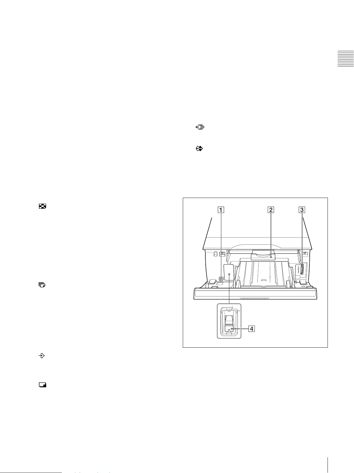
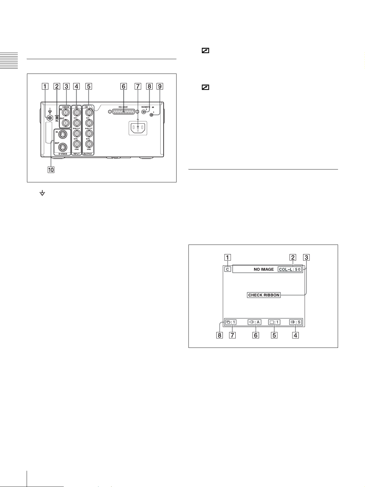
Location and Function of Parts and Controls ........ 8
Front ....................................................................... 8
Rear ...................................................................... 10
Monitor Display ................................................... 10
Preparation
Supplied Accessories ............................................... 12
Connections ............................................................. 12
Connecting Video Equipment .............................. 12
Connecting the Video Monitor ............................ 13
Making Connections to Enable Remote
Control ............................................................... 14
Operation
Before Printing ........................................................ 15
Loading the Ink Ribbon ....................................... 15
Loading the Paper ................................................ 17
Selecting the Input Signal .................................... 19
Making Full-Size Image Printouts ........................ 20
Making Printouts with the Desired User Set
Number .............................................................. 23
Making Multiple Copies of Identical Printouts ... 23
Capturing Another Image While Printing ............ 25
Making Variations of Printouts ............................. 26
Selecting the Memory Mode ............................... 26
Selecting a Memory Page .................................... 28
Making a Printout of Multiple Different Reduced
Images ...................................................................... 29
Making Printouts with a Caption .......................... 33
Making Printouts With a Caption ........................ 33
Entering a Caption ............................................... 33
Deleting Images Stored in Memory ....................... 36
Setting the Function of the STOP/CLEAR
Button ................................................................ 36
Deleting Images Stored in Memory ..................... 37
Erasing the Screen Display on the Video
Monitor .................................................................... 38
Adjustment
Functions That Can be Set on Menus ................... 40
Menu Tree ................................................................ 41
Basic Menu Operations .......................................... 42
Adjusting the Color and Picture Quality .............. 45
Compensating for the Input Signals .................... 45
Matching the Video Monitor Color to the Printer
Color .................................................................. 45
Adjusting the Printout Color ................................ 46
When a Black Frame or Lines Show up on the
Printouts ............................................................. 48
Fitting the Printout to the Paper ........................... 49
Adjusting the Color Balance ................................ 50
Specifying Colors for Adjustment (HSV
Adjustment) ....................................................... 52
Configuring HDTV-Signal Inputs and
Outputs ..................................................................... 57
Selecting the Input Signal .................................... 57
Selecting the Input Signal Type ........................... 57
Selecting the Input Signal Format ....................... 57
Selecting the Synchronization Method for Input
Signals ................................................................ 58
Selecting the Output Signal Type ........................ 58
Selecting the Downconvert Method ..................... 59
Making Various Settings ........................................ 60
Assigning Functions to the Remote Control
Unit .................................................................... 60
Adjusting the Contrast of the Printer Window
Display ............................................................... 61
Setting the Tray Light .......................................... 61
Setting the Cleaning Message Display
Function ............................................................. 61
Selecting Whether the Operation and Error Tones
Sound ................................................................. 61
Setting the Baud Rate .......................................... 62
Printing Menu Configurations ............................. 62
Displaying the Ink Ribbon Type and Remaining
Amount of the Ink Ribbon ................................. 62
Registering a User Set .......................................... 62
Miscellaneous
Precautions .............................................................. 64
Safety ................................................................... 64
Cleaning ............................................................... 64
Cleaning the thermal head and the internal
rollers ................................................................. 65
Ink Ribbon and Paper ............................................ 66
About the Color Printing Pack (UPC-21S/UPC-21L)
and Laminate Color Printing Pack (UPC-24SA/
UPC-24LA) ........................................................ 66
Specifications ........................................................... 67
Troubleshooting ....................................................... 69
If Damage is Suspected ....................................... 69
Error/Warning Messages ....................................... 71
Error Messages .................................................... 71
Warning Messages ............................................... 72
Clearing a Paper Jam ........................................... 74

8System Overview / Location and Function of Parts and Controls
Introduction
Introduction
System Overview
The UP-25MD is a color video printer that reproduces
image inputs from video equipment and other image
output devices via simple operations.
The UP-25MD has the following features:
• High picture quality and high print resolution
The printer allows you to print out high resolution
images in full color (with 256 shades per color, a total of
more than 16,700,000 colors in all) in high resolution
print mode (approximately 423 dpi).
• Menu settings to meet your printer’s specifications
By changing the printer settings, you can print multiple
reduced images on a single page or insert captions, and
create various types of printouts. (See page 26)
Ordinary print operations can be performed using the
buttons on the printer. Depending on the operation you
want perform, you can use the window display on the
printer or a connected monitor display to configure
printer settings and perform various adjustments as
necessary.
• HDTV (high-definition television) signal input support
The printer supports both 1080i and 720p signal types,
and can automatically determine the input signal type.
When you print HDTV signals or display them on a
monitor, they are output with a 16:9 aspect ratio. You can
downconvert the signals to SDTV signals with a 4:3
aspect ratio when outputting to a monitor.
Location and Function of
Parts and Controls
Front
APRINT indicator
Lights while printing is in progress.
BALARM indicator
Lights when an error such as a paper jam occurs.
CRemote sensor (page 14)
Aim the head of the remote control unit toward this
sensor.
DPrinter window display
Displays messages similar to those that appear on the
monitor, with differences occurring due to the
narrower character display range on the printer
window.
When operating menus, the printer window also
indicates the line on which the menu cursor is
positioned.
If errors occur, error messages are displayed.
The contrast of the printer window display can be
adjusted on the SYSTEM SETUP menu. (See
page 61)
EMENU button
Press this button to display the menu or to return to the
normal screen from the menu.
FDISPLAY button (page 22, 38)
When the normal screen is displayed, pressing this
button selects whether to display screen indicators
such as Q1, A, S, etc. Each press of this button toggles
the display setting ON and OFF, and the current
setting is displayed for a few seconds when the button

9
Location and Function of Parts and Controls
Introduction
is pressed. The DISPLAY setting in the OUTPUT
SETUP menu also changes in conjunction with each
press of this button.
When the menu is displayed, pressing this button
temporarily hides the menu display on the monitor.
The menu display is hidden for as long as the button
is pressed.
GDirectional buttons (<, ,, M, m)
Use these buttons to select menu items and change
settings.
HxSTOP/CLEAR button (page 36)
When printing is in progress, this button functions as
the STOP button. Press this button during continuous
printing operations to stop printing after the current
item finishes printing.
When printing is not in progress, this button functions
as the CLEAR button. Press this button to delete
images captured in memory. The images that are
deleted when the button is pressed depend on the
setting in the FUNCTION SETUP menu. If the button
is pressed while the setting is OFF, an error tone will
sound.
IMULTI PICTURE button (page 29)
Press this button during normal screen display to
select the layout (full-size, two reduced images, or
four reduced images) in which images are captured to
memory. Each press of this button switches the image
type in the following sequence: “1, 2, 4, 1...,” and the
current selection is displayed for a few seconds when
the button is pressed. The MULTI PIX setting in the
LAYOUT SETUP menu also changes in conjunction
with each press of this button.
JPRINT QTY button (page 24)
Press this button to select the number of copies to
print. You can select up to nine copies, and the current
selection is displayed for a few seconds when the
button is pressed. The PRINT QTY setting in the
PRINTER SETUP menu also changes in conjunction
with each press of this button.
You can press this button to change the number of
copies to print, even while printing is in progress.
KCAPTURE button
Press this button to capture images to memory for
printing.
LPRINT button
Press this button to print the images that are captured
to memory.
M!POWER switch
Use this switch to turn the printer on or off.
NTray light
Illuminates the output tray. (You can configure the
setting for this.) (page 61)
OPaper feed tray (page 17)
Load paper in this tray. Printouts stack in the tray
above.
PZ(eject) mark
Press here to eject the paper feed tray.
QEXEC button
Use this button to confirm a menu setting.
RMEMORY PAGE button (page 25, 28, 37)
Press this button to select the memory page to use.
SSOURCE/MEMORY button
Press this button to select the source for images that
are output to the monitor. Each press of this button
toggles between memory images and input source
images.
Inside the Ribbon Door Panel
A!POWER switch
Use this switch to turn the printer on or off. This
switch functions even while the ribbon door panel is
open.
BRibbon tray (page 15)
Load the ink ribbon in this tray.
CDial (page 74)
Use this dial to clear paper manually when an internal
paper jam occurs.

10 Location and Function of Parts and Controls
Introduction
DMedia switch lever
Switch the position of this lever according to the type
of ink ribbon being used.
Rear
AEquipotential ground terminal connector
Connects to a ground (equipotential) plug to bring the
various parts of the system to the same potential.
BNTSC/PAL switch
Switch the position as follows according to the video
signal being used.
When using NTSC video signals, set the switch to the
up position.
When using PAL video signals, set the switch to the
down position.
CVIDEO IN/VIDEO OUT (composite video signal
input/composite video signal output) connectors
(page 13)
VIDEO IN connector: Connects to video equipment
with composite video signal output connectors.
VIDEO OUT connector: Connects to video
equipment with composite video signal input
connectors.
DtINPUT (RGB/YPbPr/SYNC video signal
input) connectors (page 13)
Connects to video equipment with RGB/YPbPr signal
output connectors.
ETOUTPUT (RGB/YPbPr/SYNC video signal
output) connectors (page 12)
Connects to video equipment with RGB/YPbPr signal
input connectors.
FRS-232C connector (page 14)
Connects to a computer for controlling the printer.
G-AC IN connector (page 12)
Connects to the power cord.
HREMOTE 2 connector (stereo mini jack)
(page 14)
Connects to an RM-91 Remote Control Unit (not
supplied) or an FS-24 Foot Switch (not supplied).
IREMOTE 1 connector (page 14)
Connects to an RM-5500 Remote Control Unit (not
supplied) for wired remote control.
JS-VIDEO IN/S-VIDEO OUT (S-Video input/S-
Video output) connectors
S-VIDEO IN connector: Connects to video
equipment with S-Video signal output connectors.
S-VIDEO OUT connector: Connects to video
equipment with S-Video signal input connectors.
Monitor Display
When the printer is connected to a video monitor and
turned on, the following screen is the first screen that
appears on the monitor. (This screen is referred to as the
“normal” screen in this document.)
When the MENU button is pressed, the menu screen is
displayed.
For detailed information on the menu screen, see “Menu
Tree” on page 41.
AC (caption) display section
C is displayed when the printer is set to print a
caption.
BInk ribbon type and remaining ink ribbon display
section
Displays the ink ribbon type and the remaining
amount of ribbon (indicates the number of printouts
that can still be made with the ribbon).
CMessage display section
Usually messages are displayed on the top line of the
screen.

11
Location and Function of Parts and Controls
Introduction
Urgent messages are displayed on the center of the
screen.
DS or M (image type) display section
Indicates the type of image being displayed on the
monitor.
S (Source): The image from the input signal source
is displayed on the screen.
M (Memory): The image captured in memory is
displayed on the screen.
EPrinter operation mode display section
Indicates the printer operation mode (type of printouts
such as multiple reduced images).
AType of printout
Indicates the type of printout.
BPosition of the cursor
Indicates the position where the cursor is
currently placed and where an image will be
captured.
FMemory page display section
Indicates the currently selected memory page.
Memory pages that are currently being printed or
memory pages that are queued for printing will blink.
GPrint quantity display section
Indicates the number of copies to be printed. This item
blinks while the printer is busy.
HPrinter setting status display section
The currently selected status is displayed when either
MULTI PICTURE, PRINT QTY, or DISPLAY button
is pressed.
Position of the cursor:
1st position of four reduced images
Full-size image Two reduced
images
Four reduced
images

12 Supplied Accessories / Connections
Preparation
Preparation
Supplied Accessories
This printer is packed with the following accessories.
Check that nothing is missing from your package.
Notes
• Retain the original carton and packing materials in case
you have to transport this unit in the future.
• When transporting the printer, remove the ink ribbon and
paper feed tray, and lock the internal thermal head. For
details, see “Transportation” on page 64.
Connections
To enable printing, video equipment to act as an input
signal source, and a video monitor to display images or
menus must be connected.
The following diagrams illustrate how to make the input,
output and remote control connections. Use this as a guide
when connecting the cables required to transmit signals to
and from the equipment to be used for printing.
Notes
• Turn off the power of each device before attempting to
make any connections.
• Connect the AC power cord last.
Connecting Video Equipment
Connect the video equipment providing the video images
to be printed.
Connect the video equipment which will be used in actual
printing, using the following diagram as a guide.
Connections for HDTV-signal input and output
Use the RGB/YPbPr/SYNC video signal input and output
connectors to connect equipment that will input and output
HDTV signals.
In addition, set the NTSC/PAL switch on the rear panel of
the printer as follows, based on the video system (NTSC/
PAL) you will use.
Supported signals for the RGB/YPbPr/SYNC video signal
input and output connectors are as follows.
NTSC setting: 480/59.94i (SD), 1080/59.94i, 720/59.94p
PAL setting: 576/50i (SD), 1080/50i, 720/50p
Before Using This Printer (1)
Thermal head cleaning cartridge (1)
CD-ROM (Instructions for use) (1)
Paper feed tray (1)
Stopper (1)
Video system Switch position
NTSC • Up
PAL • Down

13
Connections
Preparation
Connecting the Video Monitor
Connect a video monitor to view captured images and to
check those to be printed. Connect a suitable video monitor
which will be used in actual printing, using the following
diagram as a guide.
Video equipment
to RGB/YPbPr/
SYNC output
connectors
to composite
video output
connector
to S VIDEO
output
connector
75-ohm
coaxial
cable with
BNC
connectors
Connecting
cable (with
DIN 4-pin
connectors)
to RGB/YPbPr/
SYNC INPUTb)
to S VIDEO
INPUT
to VIDEO
INPUT
to AC IN
AC power cord
(not supplied)
to wall outlet
a) Set the switch to match your video signal system. Set the
switch to the upper position to set the video signal system to
NTSC. Set the switch to the lower position to set the video
signal system to PAL. To switch the video signal system, turn
the power off once, then change the setting. Then, turn the
power on again. If you change the setting with the power on,
this mode will not be switched.
b) When YPbPr signal is input, it is not necessary to connect to
the SYNC connector.
75-ohm
coaxial cable
with BNC
connectors
NTSC/PAL
switch a)
to RGB/
YPbPr/SYNC
input
connectors c)
to composite
video input
connector
75-ohm
coaxial cable
with BNC
connectors
75-ohm
coaxial
cable with
BNC
connectors
Connecting
cable (with
DIN 4-pin
connectors)
to RGB/
YPbPr/
SYNC
OUTPUT
b)
to S VIDEO
OUTPUT
a) Set the switch to match your video signal system. Set the
switch to the upper position to set the video signal system to
NTSC. Set the switch to the lower position to set the video
signal system to PAL. To switch the video signal system, turn
the power off once, then change the setting. If you change the
setting with the power on, this mode will not be switched.
b) When connecting the video monitor only to the RGB/YPbPr/
SYNC OUTPUT connector without connecting to SYNC
connector, set OUTPUT SYNC in the OUTPUT SETUP menu
to ON.
c) When YPbPr signal is output, it is not necessary to connect to
the SYNC connector.
Video monitor
to wall outlet
to AC IN
AC power cord
(not supplied)
to VIDEO
OUTPUT
to S VIDEO input
connector
NTSC/PAL
switch a)

14 Connections
Preparation
Making Connections to Enable
Remote Control
The printer can be controlled remotely by connecting an
RM-5500 Remote Control Unit (not supplied), an RM-91
Remote Control Unit (not supplied), an FS-24 Foot Switch
(not supplied), or a personal computer.
Remote control
connecting cable
(supplied with the
RM-5500)
to REMOTE 1
to
REMOTE 2
to AC IN
AC power cord
(not supplied)
Computer a)
a) When connecting a personal computer, select the appropriate
baud rate from the SYSTEM SETUP menu. (See “Setting the
Baud Rate” on page 62.)
b) You can also use the remote control unit as a wireless unit. In
such a case, aim the head of the remote control unit at the
remote sensor on the printer. With fresh batteries, the range
of the remote control unit is about 3 meters.
RS-232C cable
RM-91
(not supplied)
RM-5500 b)
(not supplied)
to wall outlet
to RS-232C
FS-24
(not supplied)

15
Before Printing
Operation
Operation
Before Printing
Once the printer is connected to the computer (page 12),
you must load the paper and the ink ribbon as described
below before you can actually begin printing.
Loading the Ink Ribbon
Note
When using the printer for the first time, the thermal head
may be set to its transport position. Be sure to turn on the
printer and release the head from its transport position
before removing the ribbon tray.
Do not open the ribbon door panel if “PLEASE WAIT”
appears on the printer window display.
1
Open the ribbon door panel.
2
Switch the position of the media switch lever
according to the type of ink ribbon being used.
When using the printer for the first time or when
changing the type of ink ribbon to use, perform the
following to switch the position of the media switch
lever.
1Remove the cover.
2Switch the position of the media switch lever.
3Replace the cover.
Note
Print quality may be adversely affected if the media
switch lever is not properly positioned. Make sure that
it is set either all the way in or all the way out,
depending on the ribbon type.
3
Pull the ribbon tray straight out of the printer.
UPC-21S/UPC-21L: In UPC-24SA/UPC-24LA: Out

16 Before Printing
Operation
4
Load the ink ribbon.
1Align the two pegs on each side of the ink ribbon
with the slots on the ribbon tray.
Notes
• Make sure to load the ink ribbon with the front and
back oriented correctly.
• Before loading the ink ribbon, make sure to position
the start mark as shown below and remove any slack
by turning the gear in the direction of the arrow.
2Slide the ink ribbon straight into the ribbon tray
until completely inserted.
Note
Do not touch the white tabs on the sides of the ribbon
tray. Doing so may result in improper loading of the
ink ribbon.
5
Slide the ribbon tray straight into the printer until
completely inserted.
6
Close the ribbon door panel.
To remove the ribbon tray
To remove the ribbon tray when replacing the ink ribbon,
for example, pull the tray straight out.
Right Wrong
Start mark
Tab

17
Before Printing
Operation
If the ink ribbon tears during use
Cellophane tape, etc., can be used to repair a torn ink
ribbon so that the remainder of the ribbon can be used.
Wind the ink ribbon until the cellophane tape is no longer
visible by turning the black (or gray) gear at the winding
end in the direction of the arrow. (Make sure the ink ribbon
does not sag.)
Loading the Paper
Follow the steps below to load paper into the paper feed
tray and to insert the tray into the printer.
When using the printer for the first time, begin with step 2.
Notes
• Be careful not to touch the print side of the paper.
• Use only the recommended paper for this printer. Other
types of paper may cause printer malfunctions, such as
paper jams. For details about compatible ink ribbons and
paper, see “Ink Ribbon and Paper” on page 66.
• When the message “CHANGE RIBBON” appears on
the printer window display, the ink ribbon is used up.
Replace the ribbon and load the printer with new paper.
• Be careful when inserting and removing the paper feed
tray, because it may cause the printer to shift position and
fall.
1
Press the Zmark on the paper feed tray to eject the
tray.
2
Open the lid of the paper feed tray, and load the paper
and protective sheet together with the print side facing
up.
When using printing packs UPC-21L or
UPC-24LA
1Open the paper feed tray.
2If the paper feed tray partition is raised, lower it.
3Neatly stack and load the paper in the paper feed
tray, aligning the “v” mark on the protective sheet
with the “f” mark inside the tray.
When using printing packs UPC-21S or
UPC-24SA
1Open the feed tray.
Cellophane tape

18 Before Printing
Operation
2If the paper feed tray partition is lowered, raise it.
3Neatly stack and load the paper in the paper feed
tray, aligning the “v” mark on the protective sheet
with the “f” mark inside the tray.
Notes
• When the paper runs out, do not just add more
paper. Replace both the paper and the ink ribbon.
Replenishing the paper midway may cause a paper
jam.
• When handling the paper, do not touch the print
side. Fingerprints and dust may adhere to the print
side and soil it. To prevent the print side from
becoming soiled, handle the paper with the
protective sheet (with printed warnings) attached.
• Load the paper properly so that it fits completely in
the paper feed tray. If the paper is bent, it will
protrude from the paper feed tray and may not feed
properly. Make sure to handle each ream of paper
by the protective sheet and to remove any bends in
the paper before using it.
• Do not put a mixture of different types of paper in
the paper feed tray.
3
Remove the protective sheet and close the lid.
Note
Make sure to keep the protective sheet after removing
it. The reverse side of the protective sheet (without
printing), can be used as a cleaning sheet to clean the
thermal head. For details about cleaning, see
“Cleaning the thermal head and the internal rollers”
on page 65.
4
Insert the paper feed tray into the printer until it clicks
into place.
Notes
• If the paper feed tray cannot be completely inserted
in the printer, check the tray insertion area and
remove any paper found there.
• Do not allow more than 10 printouts to accumulate.
Leaving too many printouts in the output tray could
cause a paper jam.
Attaching the Stopper
When multiple printouts are ejected, the printouts that
accumulate on the paper feed tray may fall out. To prevent
this, attach the stopper to the paper feed tray.
1
Press the Zmark area of the paper feed tray, and
remove the tray.

19
Before Printing
Operation
2
Fit the stopper into the two slits on the lid of the paper
feed tray, and insert it all the way in.
Note
Do not pull on the metallic portion of the stopper.
Selecting the Input Signal
Before printing, select the appropriate input signal (the
input connector to which the signal to be printed is being
input) VIDEO, S VIDEO, or COMP.
1
Turn on the video monitor and the printer.
2
Press the MENU button and display the INPUT
SETUP menu by pressing the M, m, <or ,button.
3
Select INPUT SEL by pressing the Mor mbutton.
4
Select the desired input signal by pressing the <or
,button.
When you select COMP.
When you use the RGB/YPbPr INPUT connectors to
input the image data, select the appropriate type of the
input signal.
1
2, 5 2, 3, 4, 5
Highlight IN in green by pressing the M, m, <or ,
button, then the INPUT SETUP menu appears.
Source signal of the
image to be printed
Video monitor and
printer window display
(the selected input
signal is spelled out)
Signal from video equipment
connected to the VIDEO IN
connector
V tVIDEO
Signal from video equipment
connected to the S VIDEO
IN connector
SV t S-VIDEO
Signal from video equipment
connected to the RGB/
YPbPr/SYNC INPUT
connectors
CtCOMP.
Highlight INPUT SEL in green by pressing
the Mor mbutton.
Highlight the desired input signal in green by
pressing the <or ,button. The selected input
signal turns green and is spelled out.

20 Making Full-Size Image Printouts
Operation
1Select INPUT FORM. by pressing the Mor m
button.
2Select the type of the input signal by pressing the
<or ,button.
The format of the component signal output from the
RGB/YPbPr/SYNC OUTPUT connector depends on
the component signal selected here.
Note
The INPUT FORM. setting is enabled for SDTV-
signal inputs and outputs. For details about HDTV
signals, see “Configuring HDTV-Signal Inputs and
Outputs” on page 57.
When using SDTV signals, set the SD/HD SEL
setting in the HDTV SETUP menu to SD or AUTO.
(See page 57)
5
Press the MENU button.
The normal screen appears.
Making Full-Size Image
Printouts
This section explains how to make a full-size image
printout. The operations described here constitute the basic
procedure for making a printout.
Before making a full-size image printout
Make sure that the following preparations have been
performed, and refer to the reference pages as necessary.
Make sure to perform these preparations while the printer
is turned off.
• All connections should have already been made. (See
page 12.)
• Ensure that the appropriate ink ribbon/paper set is being
used and that they are correctly loaded. (See pages 15, 17
and 66.)
• Select the input signal to be used to make a printout. (See
page 19.)
• Set the printer to capture one full-size image into
memory. (See page 29.)
• Select the appropriate memory page. (See page 28.)
• Confirm the printout color quality (using, for example,
the LOAD COLOR number). (See page 46.)
1
Turn on the video monitor and the printer.
Signal input to the RGB/YPbPr/
SYNC INPUT connectors
Select
RGB input signal RGB
YPbPr input signal YPbPr
Highlight INPUT FORM. in green by
pressing the Mor mbutton.
Highlight the desired input signal in green
by pressing the <or ,button.
4
3
1
STOP/CLEAR button
DISPLAY button
SOURCE MEMORY button
Other manuals for UP25MD
1
Table of contents
Other Sony Printer manuals

Sony
Sony AC-T11 User manual

Sony
Sony DPP-F700 - Digital Photo Printer/frame Manual

Sony
Sony UPX-C200 User manual

Sony
Sony UPA-WU10 User manual

Sony
Sony OEP-4 User manual

Sony
Sony DPP-FP35 User manual

Sony
Sony UP-21MD User manual

Sony
Sony UP-DR80MD User manual

Sony
Sony UP55MD User manual

Sony
Sony UP-DR100 User manual

Sony
Sony DPP-EX50 User manual

Sony
Sony UP-DF500 User manual

Sony
Sony DPP-FP65 User manual

Sony
Sony UP860 User manual

Sony
Sony UPD-X100 User manual

Sony
Sony Professional Monitor User manual

Sony
Sony UP-CX1 series User manual

Sony
Sony DPP-SV88 User manual

Sony
Sony UP-D711MD User manual

Sony
Sony UP25MD User manual