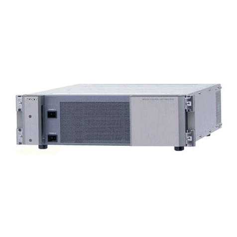
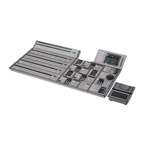
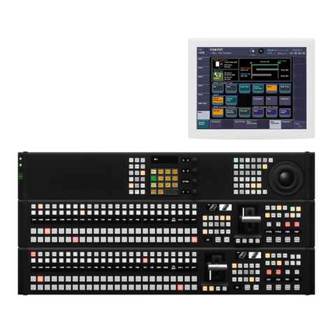
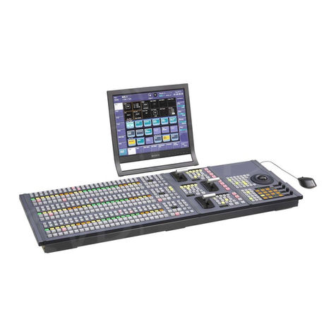
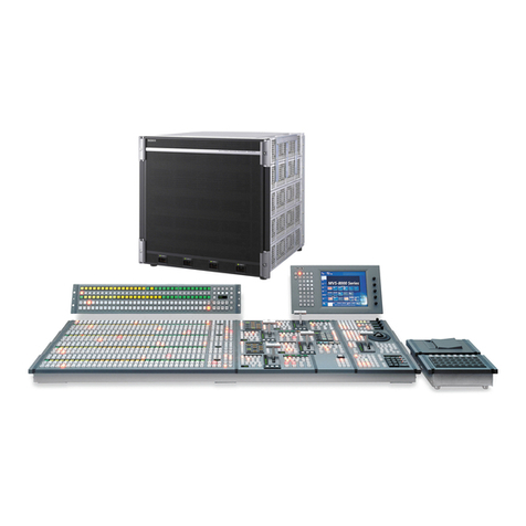
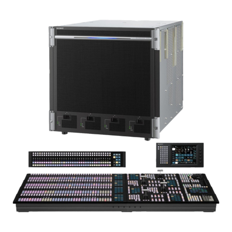
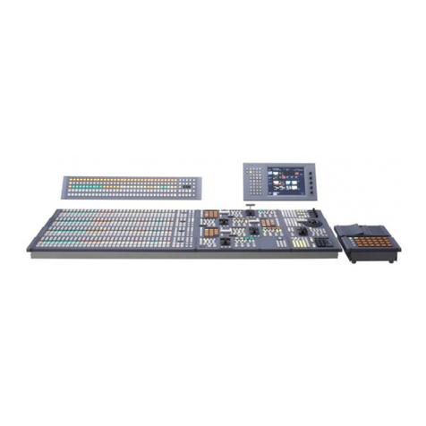
Sony XVS-9000-C User manual

SWITCHER PROCESSOR PACK
XVS-9000-C
XVS-8000-C
XVS-7000-C
XVS-6000-C
XVS-9000
XVS-8000
XVS-7000
XVS-6000
XKS-8160
XKS-8210
XKS-8440
XKS-8460
XKS-8470
XKS-8475
XKS-S8110
XKS-S8112
XKS-S8165
XKS-S8167
XKS-S9112
XKS-S9167
XKS-T8110
XKS-T8165
XKS-7210
XKS-S8111
XKS-Q8111
XKS-Q8166
XKS-C8111
XKS-C8166
XKS-C9111
XKS-C9121
XKS-C9111N
XKS-C9121N
SERVICE MANUAL
1st Edition (Revised 5)

警告
このマニュアルは,サービス専用です。
お客様が,このマニュアルに記載された設置や保守,点検,修理などを行うと感電や火災,
人身事故につながることがあります。
危険をさけるため,サービストレーニングを受けた技術者のみご使用ください。
WARNING
This manual is intended for qualified service personnel only.
To reduce the risk of electric shock, fire or injury, do not perform any servicing other than that
contained in the operating instructions unless you are qualified to do so. Refer all servicing to
qualified service personnel.
WARNUNG
Die Anleitung ist nur für qualifiziertes Fachpersonal bestimmt.
Alle Wartungsarbeiten dürfen nur von qualifiziertem Fachpersonal ausgeführt werden. Um die
Gefahr eines elektrischen Schlages, Feuergefahr und Verletzungen zu vermeiden, sind bei
Wartungsarbeiten strikt die Angaben in der Anleitung zu befolgen. Andere als die angegeben
Wartungsarbeiten dürfen nur von Personen ausgeführt werden, die eine spezielle Befähigung
dazu besitzen.
AVERTISSEMENT
Ce manual est destiné uniquement aux personnes compétentes en charge de l’entretien. Afin
de réduire les risques de décharge électrique, d’incendie ou de blessure n’effectuer que les
réparations indiquées dans le mode d’emploi à moins d’être qualifié pour en effectuer d’autres.
Pour toute réparation faire appel à une personne compétente uniquement.
利用条件:
① 本情報はソニー製品の販売,設置,設定,使用の目的でのみご利用ください。かかる
目的以外での利用を禁止します。
② 著作者の事前の書面による許可なく,本情報の全部または一部の複写,複製,転載,
改変,翻訳,送信等を禁止します。
情報改訂:
本情報は,当社の裁量により,予告なく変更されることがあります。ご使用される場合,
本情報が最新の情報であることを確認のうえ,ご使用ください。
Conditions of Use:
(1) Please use this information only for the purpose of sales, installation, configuration,
and use of Sony products. Using this information for any purpose other than the purpose
described foregoing is forbidden.
(2) Do not copy, replicate, reproduce, alter, translate, transmit, sell, lease, or distribute this
information in whole or in part without the prior written permission of the author.
Revision of Information:
This information may be changed or updated at any time without any prior notice. Please
confirm that this information is up-to-date before using it.
XVS-9000-C/XVS-8000-C/XVS-7000-C/XVS-6000-C

Model Name Serial No.
XVS-9000 (SY) 10001 and Higher
XVS-9000 (CN) 50001 and Higher
XVS-8000 (SY) 10001 and Higher
XVS-8000 (CN) 50001 and Higher
XVS-7000 (SY) 10001 and Higher
XVS-7000 (CN) 50001 and Higher
XVS-6000 (SY) 10001 and Higher
XVS-6000 (CN) 50001 and Higher
XKS-7210 (SY) 10001 and Higher
XKS-8160 (SY) 10001 and Higher
XKS-8210 (SY) 10001 and Higher
XKS-8440 (SY) 10001 and Higher
XKS-8460 (SY) 10001 and Higher
XKS-8470 (SY) 10001 and Higher
XKS-8475 (SY) 10001 and Higher
XKS-C8111 (SY) 10001 and Higher
XKS-C8166 (SY) 10001 and Higher
XKS-C9111 (SY) 10001 and Higher
XKS-C9111N (SY) 10001 and Higher
XKS-C9121 (SY) 10001 and Higher
XKS-C9121N (SY) 10001 and Higher
XKS-Q8111 (SY) 10001 and Higher
XKS-Q8166 (SY) 10001 and Higher
XKS-S8110 (SY) 10001 and Higher
XKS-S8111 (SY) 10001 and Higher
XKS-S8112 (SY) 10001 and Higher
XKS-S8165 (SY) 10001 and Higher
XKS-S8167 (SY) 10001 and Higher
XKS-S9112 (SY) 10001 and Higher
XKS-S9167 (SY) 10001 and Higher
XKS-T8110 (SY) 10001 and Higher
XKS-T8165 (SY) 10001 and Higher
XVS-9000-C/XVS-8000-C/XVS-7000-C/XVS-6000-C

CAUTION
DOUBLE POLE/NEUTRAL FUSING
安全のために,周辺機器を接続する際は,過大電圧を持
つ可能性があるコネクターを以下のポートに接続しない
でください。
:MVSLANコネクター
:UTLLANコネクター*
上記のポートについては本書の指示に従ってください。
・XVS-8000のMVSLAN,UTLLAN*,XKS-T8810/XKS-
-T8165のLANコネクターを使用の際は,輻射ノイズに
よる誤動作を防ぐため,シールドタイプのケーブルを
使用してください。
*これらは,現在サポートされていません。
For safety, do not connect the connector for periph-
eral device wiring that might have excessive volt-
age to the following ports.
: MVS LAN connectors
: UTL LAN connectors*
Follow the instructions for the above ports.
• When using the following connector, use a shiel-
ded-type cable to prevent malfunction due to
radiation noise.
XVS-8000: MVS LAN and UTL LAN* connectors
XKS-T8810/XKS-T8165: LAN connector
*: Not supported.
・12G-SDIアウトプットボードXKS-S8167/XKS-S9167
において,ケーブルを接続せずに出力を有効のまま
にした場合,電波障害を引き起こす可能性がありま
す。
ケーブルを接続しない出力端子に対しては,メニュ
ーで出力を無効に設定してください。
設定方法は,XVS-9000/XVS-8000/XVS-
7000/XVS-6000システムのユーザーズガイドをご覧
ください。
• If outputs of the 12G-SDI output board XKS-
S8167/XKS-S9167 are enabled without connect-
ing a cable, this may cause radio disturbance.
Disable unconnected output pins using the menu.
For how to set outputs, refer to the XVS-
9000/XVS-8000/XVS-7000/XVS-6000 System
User’s Guide.
• Si les sorties de la Carte de sortie 12G-SDI
XKS-S8167/XKS-S9167 sont activées sans
raccorder de câble, cela peut provoquer des
perturbations radioélectriques.
Désactivez les broches de sortie non raccordées
à l’aide du menu.
Pour savoir comment configurer les sorties,
reportez-vous au Guide de l’utilisateur du système
XVS-9000/XVS-8000/XVS-7000/XVS-6000.
• Wenn Ausgänge an der 12G-SDI Ausgangskarte
XKS-S8167/XKS-S9167 aktiviert sind, ohne dass
ein Kabel angeschlossen ist, kann dies Funk-
störungen verursachen.
Deaktivieren Sie nicht angeschlossene
Ausgangsstifte über das Menü.
Informationen zum Einstellen von Ausgängen
finden Sie im Benutzerhandbuch zum System
XVS-9000/XVS-8000/XVS-7000/XVS-6000.
CAUTION
RISK OF ELECTRIC SHOCK
The fuse in primary circuit is/could be in the neutral.
The mains shall be disconnected to de-energize the
phase conductors.
XVS-9000-C/XVS-8000-C/XVS-7000-C/XVS-6000-C

CAUTION
Danger of explosion if battery is incorrectly replaced.
Replace only with the same or equivalent type rec-
ommended by the manufacturer.
When you dispose of the battery, you must obey the
law in the relative area or country.
ATTENTION
Il y a danger d’explosion s’il y a remplacement incor-
rect de la batterie. Remplacer uniquement avec
une batterie du même type ou d’un type équivalent
recommandé par le constructeur.
Lorsque vous mettez la batterie au rebut, vous devez
respecter la législation en vigueur dans le pays ou la
région où vous vous trouvez.
VORSICHT
Explosionsgefahr bei Verwendung falscher Batterien.
Batterien nur durch den vom Hersteller empfohlenen
oder einen gleichwertigen Typ ersetzen.
Wenn Sie die Batterie entsorgen, müssen Sie die
Gesetze der jeweiligen Region und des jeweiligen
Landes befolgen.
注意
指定以外の電池に交換すると,破裂する危険があり
ます。
必ず指定の電池に交換してください。
使用済みの電池は,国または地域の法令に従って
処理してください。
FÖRSIKTIGHET!
Fara för explosion vid felaktigt placerat batteri.
Byt endast mot samma eller likvärdig typ av batteri,
enligt tillverkarens rekommendationer.
När du kasserar batteriet ska du följa rådande lagar
för regionen eller landet.
PAS PÅ
Fare for eksplosion, hvis batteriet ikke udskiftes
korrekt.
Udskift kun med et batteri af samme eller tilsvarende
type, som er anbefalet af fabrikanten.
Når du bortskaffer batteriet, skal du følge
lovgivningen i det pågældende område eller land.
HUOMIO
Räjähdysvaara, jos akku vaihdetaan virheellisesti.
Vaihda vain samanlaiseen tai vastaavantyyppiseen,
valmistajan suosittelemaan akkuun.
Noudata akun hävittämisessä oman maasi tai
alueesi lakeja.
FORSIKTIG
Eksplosjonsfare hvis feil type batteri settes i.
Bytt ut kun med samme type eller tilsvarende
anbefalt av produsenten.
Kasser batteriet i henhold til gjeldende avfallsregler.
⌞ᝅ
⌞ᝅ
ྸᴪᦘⲺ⭫⊖у↙⺤θቧՐᴿ⠼⛮Ⲻধ䲟Ⱦ
ᴪᦘж㊱ශᡌ䙖᧞㦆Ⲻ⭫⊖ශȾ
༺⨼⭫⊖ᰬθᗻ亱䚫ᆾީ൦ᡌളᇬⲺ⌋ᗁȾ
XVS-9000-C/XVS-8000-C/XVS-7000-C/XVS-6000-C


Table of Contents
Manual Structure
Purpose of this manual....................................................................................................................5
Related manuals...........................................................................................................................5
Trademarks................................................................................................................................5
1. Service Overview
1-1. Power Cord....................................................................................................................1-1
1-2. Location of Main Parts (XVS-9000)..........................................................................................1-2
1-2-1. Front and Rear Board...................................................................................................1-2
1-2-2. Other Parts..............................................................................................................1-3
1-3. Location of Main Parts (XVS-8000)..........................................................................................1-5
1-3-1. Front and Rear Board...................................................................................................1-5
1-3-2. Other Parts..............................................................................................................1-6
1-4. Location of Main Parts (XVS-7000)..........................................................................................1-7
1-4-1. Front and Rear Board...................................................................................................1-7
1-4-2. Other Parts..............................................................................................................1-8
1-5. Location of Main Parts (XVS-6000)..........................................................................................1-9
1-5-1. Front and Rear Board...................................................................................................1-9
1-5-2. Other Parts.............................................................................................................1-10
1-6. Tools and Fixtures............................................................................................................1-11
1-7. Circuit Protection Parts...................................................................................................... 1-12
1-7-1. Circuit Protection Element............................................................................................1-12
1-7-2. Replacing Fuses and IC Links.........................................................................................1-12
1-8. Lead-free Solder............................................................................................................. 1-16
1-9. Using Extension Boards..................................................................................................... 1-17
1-9-1. Extension Board EX-1132B...........................................................................................1-17
1-9-2. Extension Board EX-1296............................................................................................ 1-20
1-10. Replacement of Eject Lever of the DVP-68 Board..........................................................................1-21
1-11. Replacement of Filter........................................................................................................1-22
1-12. CA-92 and CA-92A Boards................................................................................................. 1-24
1-13. IP Video Interface (NMI) Boards............................................................................................1-25
1-13-1. Updating the Firmware................................................................................................1-25
1-14. IP Video Interface (ST2110) Boards.........................................................................................1-27
1-14-1. Displaying Web Menu.................................................................................................1-27
1-14-2. Changing Account.....................................................................................................1-28
1-14-3. Updating the Firmware (ST2110).....................................................................................1-28
1-14-4. Acquiring Log.........................................................................................................1-29
1-14-5. Installing the Software License....................................................................................... 1-30
1-14-6. Setting the SNMP Function...........................................................................................1-32
1-14-7. NMOS Function Settings..............................................................................................1-34
2. Periodic Maintenance and Inspection
2-1. Periodic Replacement Parts................................................................................................... 2-1
2-2. Cleaning.......................................................................................................................2-4
2-2-1. Cleaning the Fans.......................................................................................................2-4
XVS-9000-C/XVS-8000-C/XVS-7000-C/XVS-6000-C 1

3. Troubleshooting
3-1. XVS-9000/XVS-8000/XVS-7000/XVS-6000 Does Not Start Normally.....................................................3-1
4. Replacement of Main Parts
4-1. Tightening Torque.............................................................................................................4-1
4-2. Front Panel.................................................................................................................... 4-2
4-2-1. XVS-9000.............................................................................................................. 4-2
4-2-2. XVS-8000/7000/6000.................................................................................................. 4-3
4-3. Switching Regulator...........................................................................................................4-4
4-3-1. XVS-9000.............................................................................................................. 4-4
4-3-2. XVS-8000/7000/6000.................................................................................................. 4-5
4-4. DC Fan........................................................................................................................ 4-6
4-4-1. Fan Holder Assembly...................................................................................................4-6
4-4-2. DC Fan (Fan Holder Assembly (A))................................................................................... 4-6
4-4-3. DC Fan (Fan Holder Assembly (B)) (XVS-8000)......................................................................4-7
4-4-4. DC Fan (Fan Holder Assembly (C)) (XVS-9000)......................................................................4-8
4-5. CN-3824 Board.............................................................................................................. 4-11
4-6. Front Board.................................................................................................................. 4-12
4-7. Rear Board...................................................................................................................4-14
4-8. CN-3825 Board.............................................................................................................. 4-19
4-9. CN-3826 Board.............................................................................................................. 4-21
4-10. CN-4018 Board.............................................................................................................. 4-22
4-11. CN-4019 Board.............................................................................................................. 4-24
4-12. FP-301 Board................................................................................................................ 4-25
4-13. HN-442 Board............................................................................................................... 4-26
4-14. CNO-45 Board (XVS-9000).................................................................................................4-28
4-15. MPU-163B Board (XVS-9000/8000/7000/6000)/MPU-163C Board (XVS-9000).........................................4-29
5. Circuit Description
5-1. Cross Point Section............................................................................................................5-1
5-1-1. XPT-38 Board (XVS-9000/XVS-8000/XVS-7000/XVS-6000)........................................................5-1
5-2. M/E Block.....................................................................................................................5-3
5-2-1. MIX-57 Board (XVS-9000/XVS-8000, XKS-8210), MIX-57A Board (XVS-7000/XVS-6000, XKS-7210).........5-3
5-3. Output Processor Block....................................................................................................... 5-5
5-3-1. OUT-38 Board (XVS-8000/XVS-7000/XVS-6000)/OUT-38A Board (XKS-8160)...................................5-5
5-4. Control Section................................................................................................................5-6
5-4-1. CA-92 Board (XVS-9000/XVS-8000/XVS-7000/XVS-6000), CA-92A Board (XVS-9000).........................5-6
5-4-2. FP-255 Board (XVS-8000/XVS-7000/XVS-6000).................................................................... 5-7
5-4-3. FP-301 Board (XVS-9000).............................................................................................5-7
5-4-4. CN-3807 Board (XVS-8000/XVS-7000/XVS-6000).................................................................. 5-7
5-4-5. CN-3825 Board (XVS-8000/XVS-7000/XVS-6000) and CN-3826 Board (XVS-8000/XVS-7000/XVS-6000)..... 5-7
5-4-6. CN-4018 Board (XVS-9000), CN-4019 Board (XVS-9000).......................................................... 5-7
5-4-7. CN-4020 Board (XVS-9000)...........................................................................................5-7
5-4-8. HN-442 Board (XVS-9000)............................................................................................5-8
5-5. SDI Video Interface Section...................................................................................................5-9
5-5-1. CNI-43 Board (XKS-S8110)........................................................................................... 5-9
5-5-2. CNI-44 Board (XKS-S8111)........................................................................................... 5-9
5-5-3. CNI-45 Board (XKS-S9112)/CNI-45A Board (XKS-S8112).........................................................5-10
XVS-9000-C/XVS-8000-C/XVS-7000-C/XVS-6000-C 2

5-5-4. CNO-43 Board (XKS-S8165).........................................................................................5-11
5-5-5. CNO-44 Board (XKS-S9167)/CNO-44A Board (XKS-S8167)...................................................... 5-11
5-6. IP Video Interface Section................................................................................................... 5-13
5-6-1. NET-28 Board (XKS-T8110)/NET-28A Board (XKS-T8165)........................................................5-13
5-6-2. NET-32 Board (XKS-Q8111) and NET-32A Board (XKS-Q8166)...................................................5-14
5-6-3. NET-42 Board (XKS-C9111, XKS-C9121, XKS-C9111N, XKS-C9121N)/NET-42A Board (XKS-C8111)/
NET-42B Board (XKS-C8166)....................................................................................... 5-15
5-7. Frame Memory Section......................................................................................................5-17
5-7-1. VPR-129 Board (XKS-8440)......................................................................................... 5-17
5-8. Format Converter Section....................................................................................................5-19
5-8-1. VPR-129A Board (XKS-8460)....................................................................................... 5-19
5-9. DME Section.................................................................................................................5-20
5-9-1. DVP-53A Board (XKS-8470).........................................................................................5-20
5-9-2. DVP-68 Board (XKS-8475)...........................................................................................5-21
6. Spare Parts
6-1. Note on Repair Parts.......................................................................................................... 6-1
6-2. Exploded Views (XVS-9000)................................................................................................. 6-2
Front Panel and Switching Regulator................................................................................................6-2
Front Panel...........................................................................................................................6-3
Main Chassis.........................................................................................................................6-4
Rear.................................................................................................................................. 6-5
Fan................................................................................................................................... 6-6
6-3. Exploded Views (XVS-8000)................................................................................................. 6-7
Front Panel and Switching Regulator................................................................................................6-7
Main Chassis.........................................................................................................................6-9
Rear.................................................................................................................................6-10
6-4. Exploded Views (XVS-7000)................................................................................................6-11
Front Panel and Switching Regulator...............................................................................................6-11
Main Chassis........................................................................................................................6-13
Rear.................................................................................................................................6-14
6-5. Exploded Views (XVS-6000)................................................................................................6-15
Front Panel and Switching Regulator.............................................................................................. 6-15
Main Chassis........................................................................................................................6-17
Rear.................................................................................................................................6-18
6-6. Exploded Views (Fan)....................................................................................................... 6-19
Fan..................................................................................................................................6-19
6-7. Exploded Views (Boards)....................................................................................................6-20
CA-92/CA-92A Boards.............................................................................................................6-20
DVP-53A Board....................................................................................................................6-21
MIX-57/MIX-57A Boards..........................................................................................................6-23
OUT-38/OUT-38A Boards..........................................................................................................6-24
VPR-129/VPR-129A Boards.......................................................................................................6-26
XPT-38 Board...................................................................................................................... 6-28
CN-3807 Board.....................................................................................................................6-29
CNI-43/CNO-43 Boards............................................................................................................6-30
CNI-44 Board.......................................................................................................................6-31
NET-28/NET-28A Boards.......................................................................................................... 6-32
NET-32/NET-32A Boards.......................................................................................................... 6-34
DVP-68 Board......................................................................................................................6-36
CNI-45/CNI-45A Boards...........................................................................................................6-37
XVS-9000-C/XVS-8000-C/XVS-7000-C/XVS-6000-C 3
CNO-43/CNO-44/CNO-44A Boards...............................................................................................6-38
NET-42A/NET-42B Boards........................................................................................................ 6-39
NET-42 Board...................................................................................................................... 6-40
CNO-45/NET-42 Boards........................................................................................................... 6-41
6-8. Supplied Accessories........................................................................................................ 6-42
Supplied Accessories .............................................................................................................. 6-42
7. Diagrams
Block Diagrams.........................................................................................................................7-1
Frame Wiring (XVS-9000)............................................................................................................7-43
Frame Wiring (XVS-8000)............................................................................................................7-45
Frame Wiring (XVS-7000)............................................................................................................7-47
Frame Wiring (XVS-6000)............................................................................................................7-49
XVS-9000-C/XVS-8000-C/XVS-7000-C/XVS-6000-C 4

Manual Structure
Purpose of this manual
This manual describes the information items that premise the service based on the block-level such as service overview,
replacement of main parts, spare parts, block diagrams, frame wiring and etc. assuming use of system and service
engineers.
Related manuals
The following manuals are prepared for XVS-9000-C/XVS-8000-C/XVS-7000-C/XVS-6000-C and the optional boards
and units.
• Operation Manual (Supplied with XVS-9000-C/XVS-8000-C/XVS-7000-C/XVS-6000-C)
This manual describes the overview, system connection example and specifications of options of XVS-9000-C/
XVS-8000-C/XVS-7000-C/XVS-6000-C.
• User’s Guide (Supplied with XVS-9000-C/XVS-8000-C/XVS-7000-C/XVS-6000-C)
This manual describes the application and operation of XVS-9000-C/XVS-8000-C/XVS-7000-C/XVS-6000-C.
• Installation Manual (Available on request)
This manual is intended for use by trained system and service engineers, and describes the information on installing
the XVS-9000-C/XVS-8000-C/XVS-7000-C/XVS-6000-C.
If this manual is required, please contact your local Sony Sales Office/Service Center.
• Factory Service Manual (Available on request)
Parts list, circuit diagram, and board layouts of the unit are included to provide in formation required for part-level
service.
If this manual is required, please contact your local Sony Sales Office/Service Center.
Trademarks
Trademarks and registered trademarks described in this manual are as follows.
• Internet Explorer is a registered trademark or a trademark of Microsoft Corporation in the United States and other
countries.
• Chrome browser and Chrome are trademarks of Google Inc.
• Mozilla and Firefox are registered trademarks of the Mozilla Foundation.
Other system names and product names written in this manual are usually registered trademarks or trademarks of
respective development manufacturers.
XVS-9000-C/XVS-8000-C/XVS-7000-C/XVS-6000-C 5


Section 1
Service Overview
1-1. Power Cord
WARNING
• Use the approved Power Cord (3-core mains lead)/Appliance Connector/Plug with earthing-contacts
that conforms to the safety regulations of each country if applicable.
• Use the Power Cord (3-core mains lead)/Appliance Connector/Plug conforming to the proper ratings
(Voltage, Ampere).
If you have questions on the use of the above Power Cord/ Appliance Connector/Plug, please contact your local Sony
Sales Office/Service Center.
WARNING
• Never use an injured power cord.
• Plugging the power cord in the AC inlet, push as far as it will go.
For customers in the all European countries
1Power cord, 250 V 10 A (2.5 m) : !1-782-929-13
1AC inlet
For customers in the U.S.A.
1Power cord, 125 V 15 A (2.0 m) : !1-846-048-12
AC inlet
1
For customers in the China
Power cord, 250 V 10 A (2.5 m) : !1-833-005-12
AC inlet
XVS-9000-C/XVS-8000-C/XVS-7000-C/XVS-6000-C 1-1

1-2. Location of Main Parts (XVS-9000)
1-2-1. Front and Rear Board
Slot # Rear
DVP-68 (Option)
CA-92
MIX-57 (Option)
MIX-57 (Option)
XPT-38
DVP-68 (Option)
XPT-38
VPR-129 (Option)
VPR-129A (Option)
CA-92A
MIX-57 (Option)
MIX-57 (Option)
MIX-57 (Option)
Not used in this slot
DVP-53A (Option) / DVP-68 (Option)
Not used in this slot
DVP-53A (Option) / DVP-68 (Option)
1
2
3
4
5
6
7
8
9
10
11
12
13
14
15
16
17
18
19
20
21
22
23
24
25
Front
XPT-38
Not used in this slot
CNI-45 (Option)
CNO-44 (Option)
CNI-45 (Option)
Not used in this slot
CNI-45 (Option)
CNO-44 (Option)
CNI-45 (Option)
CNO-44 (Option)
CNI-45 (Option)
Not used in this slot
CNI-45 (Option)
CNO-44 (Option)
CNI-45 (Option)
CNO-44 (Option)
CNI-45 (Option)
Not used in this slot
CNI-45 (Option)
CNO-44 (Option)
CNI-45 (Option)
CN-4020
Not used in this slot
NET-42 (Option)
NET-42 / CNO-45 (Option)
NET-42 (Option)
NET-42 / CNO-45 (Option)
NET-42 (Option)
NET-42 / CNO-45 (Option)
NET-42 (Option)
NET-42 / CNO-45 (Option)
Front board
Board name Function Remarks
CA-92 Unit control/reference generator/GbE hub board XVS-9000
CA-92A Unit control/reference generator/GbE hub board XVS-9000
DVP-53A HD DME board XKS-8470
DVP-68 DME board XKS-8475
MIX-57 Mix/Effect board XKS-8210
VPR-129 Frame memory board XKS-8440
VPR-129A Format converter board XKS-8460
XPT-38 XPT + Multi viewer board XVS-9000
Rear board
Board name Function Remarks
CN-4020 External control board XVS-9000
CNI-45 12G-SDI Input board XKS-S9112
CNO-44 12G-SDI Output board XKS-S9167
CNO-45 100G output board XKS-C9121
NET-42 100G input board/NMI input board XKS-C9111, XKS-C9121/XKS-C9111N,
XKS-C9121N
XVS-9000-C/XVS-8000-C/XVS-7000-C/XVS-6000-C 1-2

1-2-2. Other Parts
7
16
15
14
1
Fan slot A
13
12
11
10
9
8
2
3
5
6
4Fan slot B
Fan slot C
Fan slot D
Fan slot E
No. Name Function Remarks
1 CN-3824 board FAN connection board XVS-9000
2 CN-4018 board Switch board for PSU XVS-9000
3 CN-4019 board Relay board between front switch and PSU XVS-9000
4 HN-442 board Relay board XVS-9000
5 FP-301 board Illuminated bar board XVS-9000
6 MB-1249 board Mother board XVS-9000
7 CN-4020 board Reference Input/SCS Interface/GPI I/O board XVS-9000
8 Switching regulator -Power supply unit A
(APS-406)
9 Switching regulator -Power supply unit B
(APS-406)
10 Switching regulator -Power supply unit C
(APS-406)
11 Switching regulator -Power supply unit D
(APS-406)
12 Switching regulator -Power supply unit E
(APS-406)
13 Switching regulator -Power supply unit F
(APS-406)
14 DC fan (120 square) -Right side of the XVS-9000
Rear side of the fan slot A to D
15 DC fan (120 square) -Right side of the XVS-9000
Rear side of the fan slot A to D
Continued
XVS-9000-C/XVS-8000-C/XVS-7000-C/XVS-6000-C 1-3

No. Name Function Remarks
16 DC fan (80 square) -Right side of the XVS-9000
Rear side of the fan slot E
XVS-9000-C/XVS-8000-C/XVS-7000-C/XVS-6000-C 1-4

1-3. Location of Main Parts (XVS-8000)
1-3-1. Front and Rear Board
CNO-43
4
3
2
CN-3807
17
16
15
Not used in this slot
VPR-129 (Option)
14
13
12
MIX-57 (Option)
1
Slot #
CNI-43
11
10
9
8
7
6
18
CA-92
OUT-38A (Option)
OUT-38
VPR-129A (Option)
XPT-38
MIX-57 (Option)
MIX-57 (Option)
MIX-57 (Option)
Front Rear
XPT-38
MIX-57 (Option)
Not used in this slot
5
DVP-53A (Option) / DVP-68 (Option)
CNI-43 / CNI-44 / CNI-45A / NET-32 / NET-42A (Option)
CNO-43 / CNO-44A / NET-32A / NET-42B (Option)
Front board
Board name Function Remarks
CA-92 Unit control/reference generator/GbE hub board XVS-8000
DVP-53A HD DME board XKS-8470
DVP-68 DME board XKS-8475
MIX-57 Mix/Effect board XKS-8210
OUT-38 Output processor board XVS-8000
OUT-38A Output processor board XKS-8160
VPR-129 Frame memory board XKS-8440
VPR-129A Format converter board XKS-8460
XPT-38 XPT + Multi viewer board XVS-8000
Rear board
Board name Function Remarks
CN-3807 External control board XVS-8000
CNI-43 SDI input board XKS-S8110
CNI-44 SDI input and FC connector board XKS-S8111
CNI-45A 12G-SDI Input board XKS-S8112
NET-28 IP input board XKS-T8110
NET-32 QSFP IP input and FC connector board XKS-Q8111
CNO-43 SDI output board XKS-S8165
CNO-44A 12G-SDI Output board XKS-S8167
NET-28A IP output board XKS-T8165
NET-32A QSFP IP output and FC connector board XKS-Q8166
NET-42A 100G input board XKS-C8111
NET-42B 100G output board XKS-C8166
XVS-9000-C/XVS-8000-C/XVS-7000-C/XVS-6000-C 1-5

1-3-2. Other Parts
Fan slot A
Fan slot B
Fan slot C
6
2
3
12
1
10
4
11
7
8
9
5
No. Name Function Remarks
1 CN-3824 board FAN connection board XVS-8000
2 CN-3825 board Switch board for PSU XVS-8000
3 CN-3826 board Relay board between front switch and PSU XVS-8000
4 FP-255 board Illuminated bar board XVS-8000
5 MB-1223 board Mother board XVS-8000
6 Switching regulator -Power supply unit A
(APS-406)
7 Switching regulator -Power supply unit B
(APS-406)
8 Switching regulator -Power supply unit C
(APS-406)
9 Switching regulator -Power supply unit D
(APS-406)
10 DC fan (120 square) -Right side of the XVS-8000
Rear side of the fan slot A, B, C
11 DC fan (120 square) -Right side of the XVS-8000
Front side of the fan slot A, B
12 DC fan (80 square) -Right side of the XVS-8000
Front side of the fan slot C
XVS-9000-C/XVS-8000-C/XVS-7000-C/XVS-6000-C 1-6

1-4. Location of Main Parts (XVS-7000)
1-4-1. Front and Rear Board
MIX-57A (Option)
MIX-57A (Option)
MIX-57A (Option)
DVP-53A (Option) / DVP-68 (Option)
4
3
2
CN-3807
Not used in this slot
VPR-129 (Option)
VPR-129A (Option)
13
12
1
Slot #
11
10
9
8
7
6
CA-92
OUT-38A (Option)
OUT-38
XPT-38
Front
5
CNI-43 / CNI-44 / CNI-45A / NET-32 / NET-42A (Option)
CNO-43 / CNO-44A / NET-32A / NET-42B (Option)
Rear
Front board
Board name Function Remarks
CA-92 Unit control/reference generator/GbE hub board XVS-7000
DVP-53A HD DME board XKS-8470
DVP-68 DME board XKS-8475
MIX-57A Mix/Effect board XKS-7210
OUT-38 Output processor board XVS-7000
OUT-38A Output processor board XKS-8160
VPR-129 Frame memory board XKS-8440
VPR-129A Format converter board XKS-8460
XPT-38 XPT + Multi viewer board XVS-7000
Rear board
Board name Function Remarks
CN-3807 External control board XVS-7000
CNI-43 SDI input board XKS-S8110
CNI-44 SDI input and FC connector board XKS-S8111
CNI-45A 12G-SDI Input board XKS-S8112
NET-28 IP input board XKS-T8110
NET-32 QSFP IP input and FC connector board XKS-Q8111
CNO-43 SDI output board XKS-S8165
CNO-44A 12G-SDI Output board XKS-S8167
NET-28A IP output board XKS-T8165
NET-32A QSFP IP output and FC connector board XKS-Q8166
NET-42A 100G input board XKS-C8111
NET-42B 100G output board XKS-C8166
XVS-9000-C/XVS-8000-C/XVS-7000-C/XVS-6000-C 1-7

1-4-2. Other Parts
Fan slot A
Fan slot B
2
3
1
10
4
11
6
7
8
9
5
No. Name Function Remarks
1 CN-3824 board FAN connection board XVS-7000
2 CN-3825 board Switch board for PSU XVS-7000
3 CN-3826 board Relay board between front switch and PSU XVS-7000
4 FP-255 board Illuminated bar board XVS-7000
5 MB-1233 board Mother board XVS-7000
6 Switching regulator -Power supply unit A
(APS-406)
7 Switching regulator -Power supply unit B
(APS-406)
8 Switching regulator -Power supply unit C
(APS-406)
9 Switching regulator -Power supply unit D
(APS-406)
10 DC fan (120 square) -Right side of the XVS-7000
Rear side of the fan slot A, B
11 DC fan (120 square) -Right side of the XVS-7000
Front side of the fan slot A, B
XVS-9000-C/XVS-8000-C/XVS-7000-C/XVS-6000-C 1-8
This manual suits for next models
31
Table of contents
Other Sony Switch manuals

Sony
Sony DVS-7200 User manual

Sony
Sony MVS-8000X SystemMVS-7000X System User manual

Sony
Sony DVS-V3232M User manual

Sony
Sony HDS-7100 User manual

Sony
Sony SB-V55A User manual

Sony
Sony DFS-700 User manual

Sony
Sony MCS-8M User manual

Sony
Sony MVS-8000 User manual

Sony
Sony MVS-8000X System User manual

Sony
Sony MCS-8M User manual