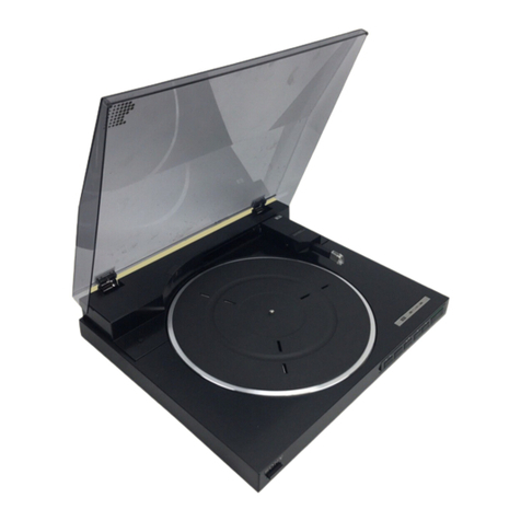
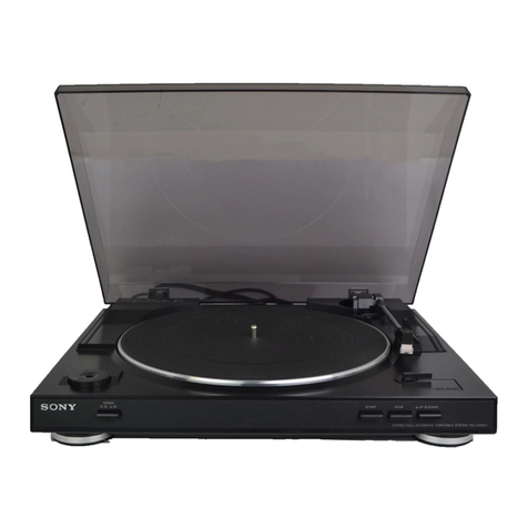
Sony PS-LX310BT User manual

Sony Video & Sound Products Inc.
SERVICE MANUAL
Conditions of Use:
(1) Please use this information only for the purpose of performing repair, maintenance and/or configuration services of the Sony products (hereinafter the “Repair services”) under the ser-
vice agreement entered into with the Sony group company (hereinafter the “Service agreement”). Using this information for any purpose other than the purpose described foregoing is
forbidden.
(2) Only the Authorized Servicer’s officers, employees or subcontractors (including their officers and employees) whose duties justify a need-to-know and who have agreed to hold
confidential this information (collectively hereinafter the “Permitted users”) are permitted to access and use this information. To disclose or disseminate to any person other than the
Permitted users is forbidden.
(3) Destroy or erase any and all portion of this information promptly in an irrecoverable and secure fashion after achieving the purpose described in Section (1) above.
(4) Do not copy, replicate, reproduce, alter, translate, transmit, sell, lease, or distribute this information in whole or in part without the prior written permission of the author.
(Notwithstanding foregoing, it is permitted to copy and distribute this information to the Permitted users.)
(5) Please notify immediately any leakage, loss, theft, misappropriation, or other misuse of this information by e-mail to the following address:
(6) In addition to the above, the terms and conditions of the Service agreement shall be applied to using this information.
Revision of Information:
This information may be changed or updated at any time without any prior notice. Please confirm that this information is up-to-date before using it.
Sony CONFIDENTIAL
For Authorized Servicer
PS-LX310BT
9-896-578-01
2019B33-1
© 2019.02
Note:
Be sure to keep your PC used for service and
checking of this unit always updated with the
latest version of your anti-virus software.
In case a virus affected unit was found during
service, contact your Service Headquarters.
SYSSET
2019/02/2300:40:47(GMT+09:00)

SERVICE MANUAL
Sony CONFIDENTIAL
For Authorized Servicer
PS-LX310BT
SPECIFICATIONS
STEREO TURNTABLE SYSTEM
US Model
Canadian Model
AEP Model
UK Model
Ver. 1.0 2019.02
Motor and Platter
Drive system
Belt-drive
Motor
DC motor
Platter
296 mm dia. (aluminum die-cast)
Speeds
33 1/3 and 45 rpm, 2 speed
Wow and utter
0.1% (WRMS)
S/N ratio
More than 50 dB (DIN-B) with the
supplied cartridge
Tone Arm
T
ype
Dynamic balanced J shaped arm
Eective arm length
197 mm
USB Connectivity (US, CND)
Output port
USB2.0 Plug-in power Type-B
Powered by PC (DC5V 100 mA)
Cartridge
T
ype
MM
Stylus pressure
3 g
Output level
2.5 mV
General
Power supply
DC 12 V 0.8 A (AC adaptor)
Power consumption
1.8 W
Dimensions
430 mm x 108 mm x 367 mm
(17 in x 4 3/8 in x 14 1/2 in)
(width/height/depth)
Weight
Approx. 3.5 kg (7 Ib 11 1/2 oz)
AC adaptor
Input
AC 100-240 V 0.35 A 50/60 Hz
Output
DC 12 V 0.8 A (AC adaptor)
BLUETOOTH section
Communication system
BLUETOOTH Specication version 4.2
Output
BLUETOOTH Specication Power
Class 2
Line of sight approx. 10 m (33 feet)*
Maximum communication range
Frequency band
2.4 GHz band (2.402 GHz - 2.480 GHz)
Modulation method
FHSS
Compatible BLUETOOTH proles*2
A2DP 1.3
Supported Codecs*3
SBC*4, Qualcomm® aptX™ audio
Transmission range (A2DP)
20 Hz - 20,000 Hz (Sampling frequency
44.1 kHz)
*1The actual range will vary depending on factors
* The 45 rpm adaptor and dust cover hinges are
attached to a side surface of your turntable's
packaging material.
such as obstacles between devices, magnetic elds
around a microwave oven, static electricity, cordless
phone, reception sensitivity, antenna's performance,
operating system, software application, etc.
*2BLUETOOTH standard proles indicate the purpose
of BLUETOOTH communication between devices.
*3Codec: Audio signal compression and conversion
format
*4Subband Codec
Design and specications are subject to
change without notice.
1
Checking the Supplied Items
t1MBUUFSXJUIESJWFCFMU
t.BUGPSUIFQMBUUFS
t%VTUDPWFS
tSQNBEBQUPS
t%VTUDPWFSIJOHFT
t"$BEBQUPS
t0QFSBUJOH*OTUSVDUJPOT
Maximum output power (AEP, UK)
≤ 4 dBm
SYSSET
2019/02/2300:40:47(GMT+09:00)

PS-LX310BT
3
Sony CONFIDENTIAL
For Authorized Servicer
SAFETY-RELATED COMPONENT WARNING!
COMPONENTS IDENTIFIED BY MARK 0OR DOTTED LINE
WITH MARK 0ON THE SCHEMATIC DIAGRAMS AND IN THE
PARTS LIST ARE CRITICAL TO SAFE OPERATION.
REPLACE THESE COMPONENTS WITH SONY PARTS WHOSE
PART NUMBERS APPEAR AS SHOWN IN THIS MANUAL OR
IN SUPPLEMENTS PUBLISHED BY SONY.
ATTENTION AU COMPOSANT AYANT RAPPORT
À LA SÉCURITÉ!
LES COMPOSANTS IDENTIFIÉS PAR UNE MARQUE 0SUR
LES DIAGRAMMES SCHÉMATIQUES ET LA LISTE DES
PIÈCES SONT CRITIQUES POUR LA SÉCURITÉ DE FONC-
TIONNEMENT. NE REMPLACER CES COMPOSANTS QUE
PAR DES PIÈCES SONY DONT LES NUMÉROS SONT DON-
NÉS DANS CE MANUEL OU DANS LES SUPPLÉMENTS
PUBLIÉS PAR SONY.
1. SERVICING NOTES ................................................ 4
2. DISASSEMBLY
2-1. Disassembly Flow.............................................................. 12
2-2. Bottom Cover..................................................................... 13
2-3. Motor Assy......................................................................... 14
2-4. MAIN Board-1................................................................... 15
2-5. MAIN Board-2................................................................... 16
2-6. MAIN Board-3................................................................... 17
2-7. Phono Cable....................................................................... 18
2-8. BT Board............................................................................ 18
2-9. Speed Knob........................................................................ 19
2-10. SPEED Board .................................................................... 20
2-11. Cam Gear Assy .................................................................. 21
2-12. How to Install Cam Gear Assy .......................................... 22
2-13. Center & Pinion Assy ........................................................ 23
2-14. Stylus ................................................................................. 24
3. ELECTRICAL ADJUSTMENT ............................. 25
4. DIAGRAMS
4-1. Printed Wiring Board - SPEED Board - ............................ 27
4-2. Printed Wiring Board - MAIN Board -.............................. 28
4-3. Schematic Diagram - MAIN Section - .............................. 29
4-4. Printed Wiring Board - BT Board -.................................... 30
4-5. Schematic Diagram - BT Board - ...................................... 31
5. EXPLODED VIEWS
5-1. Overall Section .................................................................. 32
5-2. MAIN Board Section ......................................................... 33
5-3. BT Board Section............................................................... 34
5-4. Cam Gear Section .............................................................. 35
6. ACCESSORIES .......................................................... 36
TABLE OF CONTENTS
Trademarks
tIBM and PC/AT are registered trademarks of
International Business Machines Corporation.
tMicrosoft, Windows and Windows Media are
either trademarks or registered trademarks
of Microsoft Corporation in the United States
and/or other countries.
tMac, Mac OS and macOS are trademarks of
Apple Inc., registered in the U.S. and other
countries.
tQualcomm aptX is a product of Qualcomm
Technologies International, Ltd.
tQualcomm is a trademark of Qualcomm
Incorporated, registered in the United States
and other countries, used with permission.
aptX is a trademark of Qualcomm
Technologies International, Ltd., registered
in the United States and other countries,
used with permission.
tThe BLUETOOTH® word mark and logos are
registered trademarks owned by the
Bluetooth SIG, Inc. and any use of such
marks by Sony Corporation is under license.
tAll other trademarks and registered
trademarks are trademarks or registered
trademarks of their respective holders. In
this manual, ™ and ® marks are not specied.
System requirements
Operating systems:
(US, CND)
Windows 7/Windows 8.1/Windows 10
(32/64 bit)
(The latest service pack is required.)
Mac OS X 10.9 - 10.11
macOS 10.12 - 10.14
Any operating systems other than the listed
ones are not supported.
T
he standard driver software of Windows
and Mac is supported. No installation of the
dedicated driver software is needed.
Note
A recording application is not assured to work
successfully:
–on every computer with one of the listed
operating systems
–on a homemade computer
–on a computer with a user-upgraded operating
system
–on a multi-boot computer
–with the power-saving features of the computer:
System Suspend or Sleep (Standby)
Polarity of DC output of the AC adaptor
SYSSET
2019/02/2300:40:47(GMT+09:00)

PS-LX310BT
4
Sony CONFIDENTIAL
For Authorized Servicer
SECTION 1
SERVICING NOTES
The SERVICING NOTES contains important information for servicing. Be sure to read this section before repairing the unit.
UNLEADED SOLDER
Boards requiring use of unleaded solder are printed with the lead-
free mark (LF) indicating the solder contains no lead.
(Caution: Some printed circuit boards may not come printed with
the lead free mark due to their particular size)
: LEAD FREE MARK
Unleaded solder has the following characteristics.
• Unleaded solder melts at a temperature about 40 °C higher than
ordinary solder.
Ordinary soldering irons can be used but the iron tip has to be
applied to the solder joint for a slightly longer time.
Soldering irons using a temperature regulator should be set to
about 350 °C.
Caution: The printed pattern (copper foil) may peel away if the
heated tip is applied for too long, so be careful!
• Strong viscosity
Unleaded solder is more viscous (sticky, less prone to flow) than
ordinary solder so use caution not to let solder bridges occur
such as on IC pins, etc.
• Usable with ordinary solder
It is best to use only unleaded solder but unleaded solder may
also be added to ordinary solder.
MODEL IDENTIFICATION
When identifying the destination of this unit, check the Part No. and
destination code printed on the model number label on the bottom
side of the main unit.
Note: The Part No. suffix printed on the model number label may be
changed in the midway of production.
– Bottom view –
front side
Model number label
Part No.
Destination code
Part No. Destination code Destination
5-000-939-01 UC2 US, CND
5-000-939-11 CEL AEP
5-000-939-21 CEK UK
DESTINATION ABBREVIATIONS
The following abbreviations for model destinations are used in this
service manual.
• Abbreviations
AEP : European area (Except for UK, Ireland), East European
area, CIS area (Moldova) and Middle East area (Israel)
models
CND : Canadian model
UK : European area (UK, Ireland) model
SYSSET
2019/02/2300:40:47(GMT+09:00)

PS-LX310BT
5
Sony CONFIDENTIAL
For Authorized Servicer
BLUETOOTH CONNECTION CHECKING METHOD
When the BT board or MAIN board is replaced, refer to following,
check the Bluetooth connection.
Note 1: Do not connect to headphones for which you cannot adjust the vol-
ume. Audio tracks may be played at very loud volumes.
Procedure:
1. Place the playback device that supports BLUETOOTH wireless
technology, to which you want to connect, as close to your turn-
table as possible.
This unit
Playback device that
supports BLUETOOTH
wireless technology, to
which you want to connect
(Above illustration is
reference example)
2. Press and hold your turntable’s [ PAIRING] button for about
2 seconds, and then release it. The [ PAIRING] indicator rap-
idly flashes blue.
3. Turn on the pairing mode for the playback device that supports
BLUETOOTH wireless technology, to which you want to con-
nect.
The above illustration is one example of a device that is connect-
ing.
For how to turn on the pairing mode for the device to which you
want to connect, refer to the user’s instructions supplied with the
device.
The [ PAIRING] indicator stops flashing blue and remains lit
when pairing is complete.
Note 2: If you are only using the BLUETOOTH connection and not con-
necting your turntable to another device using the audio cable, set
the [OUTPUT SELECT] switch on the back of the turntable to
LINE to use the turntable.
4. Press the [START] button on this unit to start the playback,
check that the sound output from the playback device that sup-
ports BLUETOOTH wireless technology.
5. Detach the playback device that supports BLUETOOTH wire-
less technology about 10 m from this unit, check that connection
keeps without problems at that position.
about 10 m
Note 3: Even if there is no problem with connection at the state that
distance between this unit and playback device that supports
BLUETOOTH wireless technology is about 1 m, the connection
may be lost if distance is about 10 m. In that case, the electrical
parts (Ref. No. CT02, CT03) on the BT board may be mounted
incorrectly or damaged.
If there is no problem with connection at the distance is about 1
m and connection is lost at the distance is about 10 m, replace
the BT board with a new part, check the BLUETOOTH connec-
tion again from step 1.
– BT Board (Side B) –
– Continued on next page –
SYSSET
2019/02/2300:40:47(GMT+09:00)

PS-LX310BT
6
Sony CONFIDENTIAL
For Authorized Servicer
6. Press the [STOP] button on this unit to stop the playback.
Then press the [ PAIRING] button, check that [ PAIR-
ING] indicator lights off.
STOP
7. Press and hold down the [ PAIRING] button on this unit
about 10 seconds, delete the device information and complete
the checking work.
Tip
• Once you have paired your turntable and device,
you can connect to the paired device simply by
giving a short press to the BLUETOOTH button/
PAIRING button to enable your turntable's
BLUETOOTH function. You can also connect to
the paired device and play vinyl records by
pressing the START button on the front of the
turntable when the BLUETOOTH indicator is lit
orange (in standby).
• Press the BLUETOOTH button/ PAIRING
button to disengage from the BLUETOOTH
connection. The BLUETOOTH indicator turns off.
• You can register information for a maximum of
8 devices paired to your turntable.
You can delete all information for paired devices
by pressing and holding the BLUETOOTH
button/ PAIRING button for about 10 seconds,
and then releasing it.
If you cannot register (pair) devices
• If there are playback devices, which
support BLUETOOTH wireless technology
nearby, that have the BLUETOOTH
function enabled, but some of them are
not the device with which you want to
pair, disable their BLUETOOTH function
and try pairing again.
• With the pairing operation, the device
with which you do not want to pair may
be turned on and connected to the
turntable automatically. If this occurs,
change the device's setting not to turn on
by the BLUETOOTH connection, turn off
the device, and try pairing again.
• You cannot pair your turntable with
smartphones, TVs, or computers. The
turntable can use the BLUETOOTH
function to send data to playback devices
that support BLUETOOTH wireless
technology; however, because the
turntable cannot receive data from
smartphones, TVs, or computers, the
turntable cannot pair with them.
CHECK OF STORAGE HOLE FOR THE 45 RPM ADAPTOR
There is storage hole for the 45 rpm adaptor on the right side of this
unit.
Since customer might be storing the 45 RPM adaptor in this storage
hole, check whether there is the 45 RPM adaptor before working,
and be careful of falling, loss, damage etc.
Storage hole
for the 45
rpm adaptor
REPAIRING OF EACH BOARD
When boards installed in this unit are defective, in all cases, boards
will be replaced.
The electrical parts mounted on the each board cannot be replaced
for repairing.
When the each board is defective, replace the individual board with
complete mounted board.
SYSSET
2019/02/2300:40:47(GMT+09:00)

PS-LX310BT
7
Sony CONFIDENTIAL
For Authorized Servicer
ASSEMBLING THE STEREO TURNTA-
BLE SYSTEM
This unit is a product of the specification that
the customer self assembled.
When it is necessary to assemble this unit for
the operation check, refer to following.
Note
• When you purchased your turntable, a stylus's
protective cover was attached to the stylus.
Leave on the cover as you assemble your
turntable.
• Do not connect your turntable to a power outlet
with the AC adaptor until you are finished with
assembly.
• The stylus is a high precision component. Do not
touch the stylus while handling it. Touching the
stylus with your fingers, or banging the stylus
into the platter, may cause damage to the stylus.
• To move your turntable after assembling the
turntable,
– attach the stylus's protective cover,
– remove the platter, and
– pass a string through the hole in the tone arm
rest and fix the tone arm and the tone arm
rest.
Precautions on placement
• Place the unit on a level surface.
• Avoid placing the unit near electrical
appliances (such as a television, hair
dryer, or fluorescent lamp) which may
cause hum or noise.
• Place the unit where it will not be subject
to any vibration, such as from speakers,
slamming of doors, etc.
• Keep the unit away from direct sunlight,
extremes of temperature, and excessive
dust and moisture.
• Keep the unit away from electronic
devices that may emit radio waves or
electromagnetic noise.
Attaching the platter
1 Place the platter on the spindle.
Keep the platter level while placing it on
the spindle.
Spindle
Platter
Motor
pulley
Note
Hold the platter firmly so as not to drop the
platter as it may cause personal injuries or
damage to your turntable.
2 Turn the platter to the position
where you can see the motor pulley
through the rectangular hole with
the tips of the red ribbon taped on
the platter.
Note: When the customer has been assembled this
unit once, red ribbon might not be installed.
Motor pulley
Red ribbon
3 Peel off the adhesive tape, pull and
hold the red ribbon, and then hook
the drive belt around the motor
pulley.
Note: When the customer has been assembled this
unit once, red ribbon might not be installed.
Note
• Be careful to not let the drive belt twist. If the
drive belt is twisted while placing it around
the motor pulley, the speed will become
unstable and the platter will stop after it
begins rotating. If this happens, place the
drive belt around the motor pulley again.
• When placing the drive belt around the
platter, do not stretch the drive belt roughly.
Doing so degrades the drive belt, which
causes the sound's pitch to fluctuate and be
too high.
• If the drive belt comes off of the platter's
inner circle while you are placing the drive
belt around it, temporarily remove the
platter. Turn the platter over and wind the
drive belt around the circumference of the
inner circle. Then, start again from the
beginning of the procedure.
• Be sure to remove the red ribbon after you
place the drive belt around the motor pulley.
The red ribbon is intended to help you with
this work. Placing the drive belt around the
motor pulley is still possible without the red
ribbon. The red ribbon is no longer needed
once you have attached the platter.
4 Place the mat for the platter onto
the platter.
Attaching the dust cover
1 Insert the supplied dust cover
hinges to the hinge pockets on the
dust cover.
Hinge pockets
Dust cover hinges
2 Align the attached hinges with the
hinge pockets on the rear of your
turntable and push in the dust
cover.
Tip
To remove the dust cover from the turntable,
fully open the dust cover, grasp both sides
near the bottom of the cover, and then gently
pull it out in the upward direction.
SYSSET
2019/02/2300:40:47(GMT+09:00)

PS-LX310BT
8
Sony CONFIDENTIAL
For Authorized Servicer
CLEANING THE STYLUS AND REPLAC-
ING THE STYLUS
Cleaning the Stylus
The stylus is a high precision component.
Handle it with care to avoid damage.
Use a commercial cleaning product for
cleaning the stylus.
Replacing the Stylus
The stylus may become worn out, damaged,
or dirty beyond cleaning depending on
your use case. In such a case, replace the
stylus.
Note
• Do not use a replacement stylus made by
another company.
• Be sure to attach the stylus protective cover
before you replace the stylus so as not to harm
your fingertips or damage the stylus.
To remove the stylus
1 Turn off your turntable and the
connected audio device and unplug
the AC adaptor from the power
outlet.
2 Attach the stylus protective cover to
the stylus.
3 Hold the cartridge body () with
one hand, grasp the stylus with the
other, and then pull the stylus in the
direction of the arrow to remove it
from the cartridge body.
To attach the stylus
1 Attach the stylus protective cover to
the spare stylus.
2 Hold the cartridge body () with
one hand and then insert the tab on
the spare stylus into the receptacle
on the cartridge body.
3 Push the stylus in the direction of
the arrow until it clicks into place.
REPLACING THE DRIVE BELT
The drive belt will wear or may even break
over time. In such a case, replace it with a
new one.
1 Turn off your turntable and the
connected audio device and unplug
the AC adaptor from the power
outlet.
2 Remove the mat for the platter.
3 Unhook the drive belt from the
motor pulley.
4 Put your finger and thumb into the
platter's round holes to hold the
platter and remove the platter.
5 Turn the platter upside down and
remove the drive belt.
6 Wind a new drive belt around the
platter while keeping it untwisted.
Note
Spare drive belts do not have the red
indication ribbon attached.
SYSSET
2019/02/2300:40:47(GMT+09:00)
PS-LX310BT
9
Sony CONFIDENTIAL
For Authorized Servicer
NOTE BEFORE MOVING OR DISASSEMBLING THIS UNIT
When moving this unit such as carrying it while assembled, or when
disassembling it, make sure to take the measures below.
Moving or disassembling this unit without taking the measures be-
low might cause parts to fall off and result in malfunction.
Procedure:
1. Install the stylus protective cover.
Note 1: When there is not stylus protective cover, refer to “CLEANING
THE STYLUS AND REPLACING THE STYLUS” on page 8, re-
move the stylus.
2. Remove the mat for the platter and the turn table (platter).
3. Fix the tone arm.
tone arm arm rest
Wrap something such as cloth
around the area where the
tone arm and arm rest touch.
Note 2: If there is a soft string to
secure the tone arm in
place and prevent damage,
this step is unnecessary.
Pass the string through the hole
on the arm rest.
Tie the string over the tone arm,
and secure the tone arm to the
arm rest so that it does not move.
Completed figure
hole of arm rest
4. Install the duct cover.
When carrying this unit, hold the bottom of this unit firmly with
both hands.
When facing the top side down and disassembling, lay down a soft
cloth, etc. and then place this unit on top of it to prevent damage.
soft cloth, etc.
When facing the top side down without installing the dust cover for
disassembly, place stands, etc., and place this unit on top of them.
Arrange the stands to the appropriate positions based on the disas-
sembly work.
Note 3: Arrange the stands so that they do not touch the tone arm.
stand, etc.
stand, etc.
SYSSET
2019/02/2300:40:47(GMT+09:00)
PS-LX310BT
10
Sony CONFIDENTIAL
For Authorized Servicer
SPEED ADJUSTMENT SHEET (STROBOSCOPE)
This speed adjustment sheet to be used in the electrical adjustment. (Refer to page 25)
The following figure by enlarge to 200 % to become diameter 292 mm, and print it.
Note: Because magnification error may occur by the printer you want to use, please to fine-adjust the magnification.
292 mm
SYSSET
2019/02/2300:40:47(GMT+09:00)
MEMO
PS-LX310BT
11
Sony CONFIDENTIAL
For Authorized Servicer
SYSSET
2019/02/2300:40:47(GMT+09:00)

PS-LX310BT
12
Sony CONFIDENTIAL
For Authorized Servicer
SECTION 2
DISASSEMBLY
• This set can be disassembled in the order shown below.
2-1. DISASSEMBLY FLOW
SET
2-2. BOTTOM COVER
(Page 13)
2-3. MOTOR ASSY
(Page 14)
2-8. BT BOARD
(Page 18)
2-4. MAIN BOARD-1
(Page 15)
2-9. SPEED KNOB
(Page 19)
2-14. STYLUS
(Page 24)
2-11. CAM GEAR ASSY
(Page 21)
2-12. HOW TO INSTALL CAM GEAR ASSY
(Page 22)
2-13. CENTER & PINION ASSY
(Page 23)
2-10. SPEED BOARD
(Page 20)
2-5. MAIN BOARD-2
(Page 16)
2-6. MAIN BOARD-3
(Page 17)
2-7. PHONO CABLE
(Page 18)
Note: Before disassembly working, make sure to refer to “NOTE BEFORE MOVING OR DISASSEMBLING THIS UNIT” on page 9.
SYSSET
2019/02/2300:40:47(GMT+09:00)
PS-LX310BT
13
Sony CONFIDENTIAL
For Authorized Servicer
Note: Follow the disassembly procedure in the numerical order given.
2-2. BOTTOM COVER
1seven screws
(P3 u10)
1screw
(P3 u10)
2screw
(STEP PTPWH3 u12)
3rubber foot
5bottom cover
4Remove the bottom cover in
the direction of the arrow.
bottom side
front side
left side
soft cloth, etc.
SYSSET
2019/02/2300:40:47(GMT+09:00)

PS-LX310BT
14
Sony CONFIDENTIAL
For Authorized Servicer
2-3. MOTOR ASSY
1Peel off the bond fixing the motor wire,
remove the four solders.
2two screws
(STEP F3 u6.5)
Note 3: If you remove the two screws (step 2), the motor
assy will fall.
When removing the screws, make sure to remove
the screws while holding the motor assy so that
it does not fall.
Turn over.
3motor assy
• Motor wire setting
motor assy
[white: 1 pin]
[white: 2 pin]
[red]
[black]
bottom side
left side
front side
stand, etc.
top side
rear side
left side
SPEED board
[white: 1 pin] [white: 2 pin]
motor wire connection
connector (CN004)
front side
rear side
front side
rear side
bond
Note 2: Fix the motor wire with using the bond of
commercial products.
Note 1: When the motor assy is replaced, make sure to refer to “SEC-
TION 3. ELECTRICAL ADJUSTMENT” on page 25 and per-
form the speed adjustment.
SYSSET
2019/02/2300:40:47(GMT+09:00)

PS-LX310BT
15
Sony CONFIDENTIAL
For Authorized Servicer
2-4. MAIN BOARD-1
• Continued on 2-5 (page 16).
1screw
(P2.6 u8)
2ground wire
3shield
(See Fig. A)
5Peel off the tape with bond.
tape
1RWHDERXWLQVWDOOLQJWKHVKLHOG
)LJ$!
)LJ%!
&DUWULGJHZLUHVHWWLQJ
4Remove the five solders.
(See Fig. B)
7Remove the solder.
ground wire
BT board cable (3P)
BT board cable (5P)
6Peel off the ground wire, BT board
cable (3P) and BT board cable (5P)
with bond.
OK 1*
,QVWDOODWLRQGLUHFWLRQIRUWKHOXJWHUPLQDO
–%RWWRPYLHZ–
Caulking is upward. Caulking is downward.
OK 1*
1two screws
(P2.6 u8)
:LUHVHWWLQJ
–%RWWRPYLHZ–
MAIN board
ground wirebond
BT board
cable (5P)
front side
rear side
Shield does not cover
the screw hole.
Shield covers
the screw hole.
shield screw hole shield screw hole
front side
rear side
MAIN board
[black]
[natural]
[red]
[natural]
[white]
stand, etc.
stand, etc.
bottom side
rear side
front side
–%RWWRPYLHZ–
BT board
cable (3P)
Note: Fix the tape, ground wire, BT board cabel (3P)
and BT board cabel (5P) with using the bond
of commercial products.
SYSSET
2019/02/2300:40:47(GMT+09:00)
PS-LX310BT
16
Sony CONFIDENTIAL
For Authorized Servicer
2-5. MAIN BOARD-2
• Continued on 2-6 (page 17).
1Remove the BT board cable (3P) (CN904).
(See Fig. C)
2Remove the BT board cable (5P) (CN903).
(See Fig. C)
3Peel off the bond fixing the BT board
cable (3P), and draw the BT board
cable (3P) out of the rib.
(See Fig. C)
4Peel off the bond fixing the BT board
cable (5P), and draw the BT board
cable (5P) out of the rib.
(See Fig. C)
7Remove the phono cable
from the groove.
8five screws
(P2.6 u8)
6switch cable
connector (CN003)
5motor assy cable
connector (CN001)
%7ERDUGFDEOH3DQG%7ERDUGFDEOH3VHWWLQJ
3KRQRFDEOHVHWWLQJ
Install the phono cable as shown figure below.
front side
rear side
phono cable
groove
groove
groove
MAIN
board
stand, etc.
stand, etc.
front side
rear side
bottom side
front
side
rear
side
–%RWWRPYLHZ–
BT board
CN904
CN903
BT board cable (3P) BT board cable (5P)
)LJ&!
groove
bondbond
BT board cable (5P)
BT board cable (3P)
three ribs
Note: Fix the BT board cable with using
the bond of commercial products.
SYSSET
2019/02/2300:40:47(GMT+09:00)
PS-LX310BT
17
Sony CONFIDENTIAL
For Authorized Servicer
2-6. MAIN BOARD-3
1Lift up the MAIN board
block in the direction of
the arrow.
2Remove the MAIN board block
in the direction of the arrow.
3Draw the button, jack, port and two
switches out of the five holes.
4MAIN board block
Note 2: When installing the MAIN baord block, align
the two screw holes and two holes.
5button
6MAIN board
screw hole
screw hole
hole
hole
1RWHDERXWLQVWDOOLQJWKH0$,1ERDUG
OK
1*
BT board cable (3P) is pressed
by the MAIN board.
BT board cable (3P) is not pressed
by the MAIN board.
MAIN board
MAIN board
BT board cable (3P)
rear side
rear side
rear side
bottom side
front side
stand, etc.
Note 1: When the MAIN board is replaced, make sure to refer to
“BLUETOOTH CONNECTION CHECKING METHOD” on
page 5 and check the Bluetooth connection.
SYSSET
2019/02/2300:40:47(GMT+09:00)

PS-LX310BT
18
Sony CONFIDENTIAL
For Authorized Servicer
2-7. PHONO CABLE
1Peel off the bond fixing the phono cable
wire, remove the four solders.
2phono cable
3KRQHFDEOHZLUHVHWWLQJ
Note: Fix the phono cable wire with using the bond of commercial
products.
bond
bond
[red] [black]
[white] [black] MAIN board
front side
rear side
phono cable
(for L-ch)
phono cable (for R-ch)
MAIN board
bottom side
rear side
front side
2-8. BT BOARD
1BT board cable (3P)
connector (CN904) 2BT board cable (5P)
connector (CN903)
4Remove the BT board in
the direction of the arrow.
hole
3four screws
(P2.6 u8)
5BT board
Note 2: When installing the BT board, align
the three bosses and three holes.
hole
boss
boss
boss
hole
left side
front side
bottom side
stand, etc.
stand, etc.
Note 1: When the BT board is replaced, make sure to refer to “BLUE-
TOOTH CONNECTION CHECKING METHOD” on page 5
and check the Bluetooth connection.
SYSSET
2019/02/2300:40:47(GMT+09:00)

PS-LX310BT
19
Sony CONFIDENTIAL
For Authorized Servicer
2-9. SPEED KNOB
1Insert a flathead screwdriver into the
two holes, and push the speed knob.
2speed knob
How to install the speed knob
When installing the speed knob to the rotary encoder, align
the directions of the D-shaped tip of the rotary encoder and
the D-shaped notch at the inner side of the speed knob.
hole
hole
SPEED board
front side
bottom side
speed knob
rotary encoder
front side
top side
right side
SYSSET
2019/02/2300:40:47(GMT+09:00)

PS-LX310BT
20
Sony CONFIDENTIAL
For Authorized Servicer
2-10. SPEED BOARD
2SPEED board
accessory nut
3SPEED board
accessory washer
4SPEED board
SPEED board
1motor assy cable connector
(CN004)
Turn over.
front side
bottom side
right side
top side
front side
right side
Note: If you remove the nut and washer (step 2, 3),
the SPEED board will fall.
When removing the nut and washer, make sure
to remove the nut and washer while holding the
SPEED board so that it does not fall.
SYSSET
2019/02/2300:40:47(GMT+09:00)
Other manuals for PS-LX310BT
3
Table of contents
Other Sony Turntable manuals

Sony
Sony PS-Q7 User manual

Sony
Sony LocationFree LFA-PC2 User manual

Sony
Sony DD-57 User manual

Sony
Sony PS-LX120D User manual

Sony
Sony NW-A45 User manual

Sony
Sony PS-X55 User manual

Sony
Sony XD-AX10 User manual

Sony
Sony NW-E99 - Network Walkman User manual

Sony
Sony WALKMAN NW-WM1A User manual

Sony
Sony PMW-PZ1 User manual

Sony
Sony AIVA AZ-BS1 User manual

Sony
Sony PS-J10 Primary User manual

Sony
Sony PS-LX2 User manual

Sony
Sony PS-2700 User manual

Sony
Sony PS-LX300USB - USB Stereo Turntable System User manual

Sony
Sony PS-F9 User manual

Sony
Sony PS-LX60 User manual

Sony
Sony PS-HX500 User manual

Sony
Sony PS-LX300USB - USB Stereo Turntable System User manual

Sony
Sony PS-D707H User manual