Speco O2D11M User manual

MB12-7MH
Owner’s Manual
O2D11M
2MP 1080p H.265 Indoor/Outdoor
Dome IP Camera

O
O2
2D
D1
11
1M
M
U
Us
se
er
r’
’s
s
G
Gu
ui
id
de
e
Rev.1.4 (Oct. 2016)
2
Caution
Any changes or modifications in construction of this device which are not explicitly approved by the
party responsible for compliance could void the user’s warranty.
Note
This equipment has been tested and found to comply with the limits for a Class A digital device,
pursuant to part 15 of the FCC Rules. These limits are designed to provide reasonable protection
against harmful interference in a residential installation. This equipment generate, uses and can
radiate radio frequency energy and, if not installed and used in accordance with the instructions, may
cause harmful interference to radio communications. However, there is no guarantee that interference
will not occur in a particular installation. If this equipment does cause harmful interference to radio or
television reception, which can be determined by turning the equipment off and on, the user is
encouraged to try to correct the interference by one or more of the following measures:
Reorient or relocate the receiving antenna.
Increase the separation between the equipment and receiver.
Connect the equipment into and outlet on a circuit different from that to which the receiver is
connected
Consult the dealer or an experienced radio/TV technician for help.
Directions
Be careful not to cause any physical damage by dropping or throwing the camera. Especially keep the
device out of reach from children.
Do not disassemble the camera. No after service is assumed when disassembled.
Use only power adapters compatible with the unit.
Be careful to prevent moisture or water penetration into the unit. Particular attention is needed when
installing the unit. The screw holes for the installation screws and pipe should be maintained water tight
during the whole life time of the product.
All the electrical connection wires running into the unit should be prepared so that water from the outside
cannot flow into the unit through the surface of the wires. Penetration of the moisture through the wire for
extended period can cause malfunction of the unit or deteriorated image.

O
O2
2D
D1
11
1M
M
U
Us
se
er
r’
’s
s
G
Gu
ui
id
de
e
Rev.1.4 (Oct. 2016)
3
Revision History
Date
Revision
Details
Oct 26th, 2016
1.4
First manual revision creation.

O
O2
2D
D1
11
1M
M
U
Us
se
er
r’
’s
s
G
Gu
ui
id
de
e
Rev.1.4 (Oct. 2016)
4
Contents
1. Introduction....................................................................................................................................................5
1.1. Overview...............................................................................................................................................5
1.2. Specification..........................................................................................................................................6
1.3. Applications of O2D11M .......................................................................................................................8
2. Product Description ......................................................................................................................................9
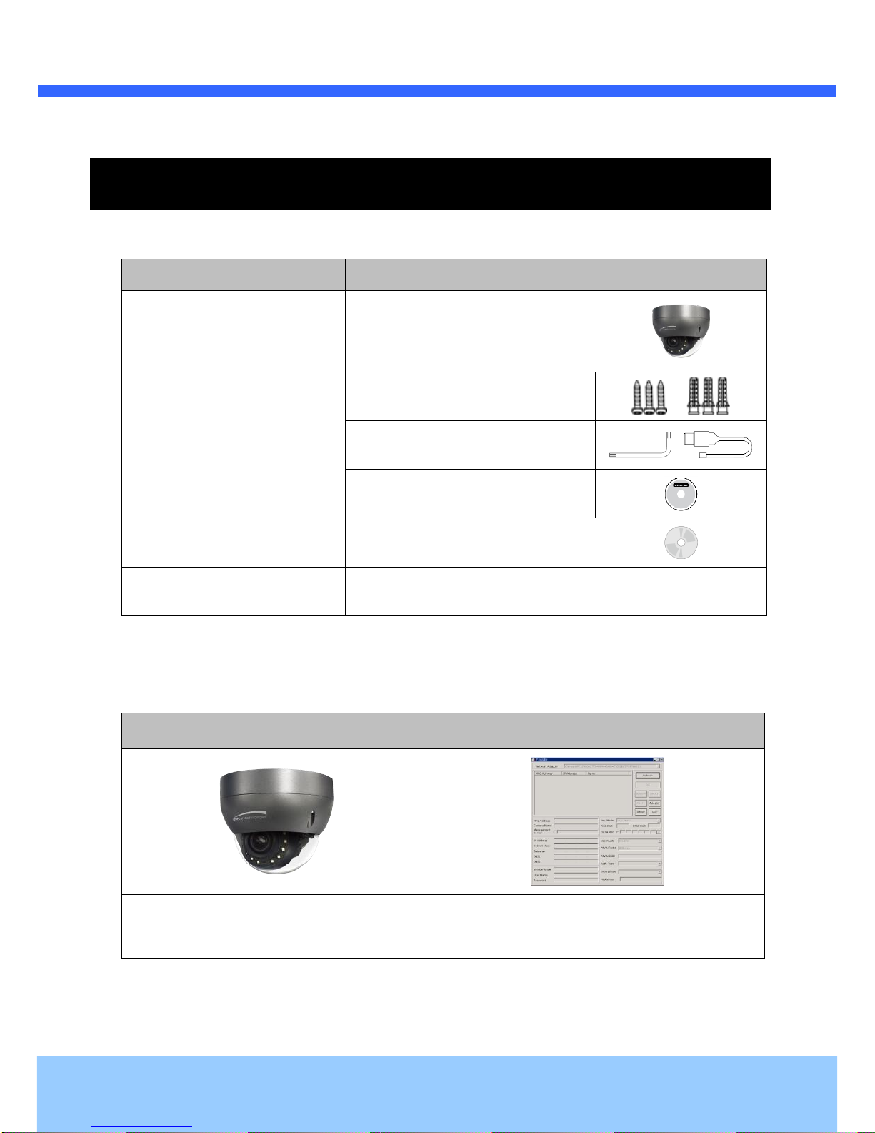
2.1. Contents................................................................................................................................................9
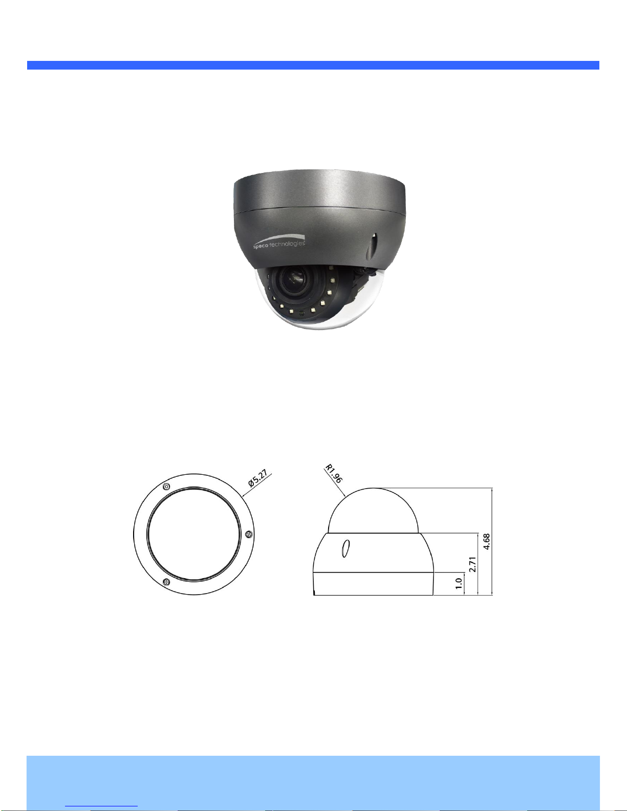
2.2.Product Preview....................................................................................................................................9
2.3.Physical description ............................................................................................................................10
2.3.1.External View............................................................................................................................10
2.3.2.Dimension.................................................................................................................................10
2.3.3. External Connector...................................................................................................................11
2.3.4. Factory Default Switch..............................................................................................................11
2.3.5.Camera Control (SW3 /SW4) ...................................................................................................12
2.4. Functional Description ........................................................................................................................12
3. On Site Installation ......................................................................................................................................14
4. Getting Started.............................................................................................................................................15
4.1. PC Requirement .................................................................................................................................15
4.2. Quick Installation Guide......................................................................................................................15
4.2.1. Connect PC and O2D11M to network. .....................................................................................15
4.2.2.Set IP parameters on O2D11M.................................................................................................16
4.2.3. Remote video connection to O2D11M......................................................................................17
4.2.4.Additional settings through connection to the Admin Page ......................................................18
5. Troubleshooting...........................................................................................................................................19
5.1. No power.............................................................................................................................................19
5.2. Cannot connect to the Video...............................................................................................................19
5.3.Technical Assistance...........................................................................................................................20
AppendixA–ImportantNotice inExchanging SDCard (MicroSD).........................................................................21

O
O2
2D
D1
11
1M
M
U
Us
se
er
r’
’s
s
G
Gu
ui
id
de
e
Rev.1.4 (Oct. 2016)
5
1. Introduction
1.1. Overview
The ONSIP O2D11M is multi-codec (H.265, H.264, MJPEG) IP camera (or network camera) built with
embedded software and hardware technology. It enables real time transmission of synchronized video up to
2MP and audio data. Remote clients can connect to IP Camera for the real time video/audio data through
various client solutions running on PC or smart device. Real time 2-way communication is available through
bidirectional audio communication feature.
H.265 is 40-50% reduction in bitrate at the same visual quality compared to H.264.
Designed to be a stand-alone streaming audio & video transmission device, The Product can be applied to
various application area such as video security, remote video monitoring, distance education, video conference
or internet broadcasting system.
Vandal proof and weather proof housing will extend the application area to harsh environment of wide
temperature range. Embedded PoE (Power over Ethernet, IEEE 802.3af) will enable the owner to reduce TCO
(Total Cost of Ownership) by reducing on-site wiring works for the installation.

O
O2
2D
D1
11
1M
M
U
Us
se
er
r’
’s
s
G
Gu
ui
id
de
e
Rev.1.4 (Oct. 2016)
6
1.2. Specification
Camera
Image sensor
1/3 Inch Progressive scan 2Mega CMOS
effective Pixel
1944 x 1092 pixels
Scanning System
Progressive scan
S/N Ratio
More than 50dB(AGC Off)
Lens
2.8 ~ 12mm Motorized Varifocal(F 1.4)
Angular of View
Diagonal 120.8˚(W) ~ 36˚(T)
IR Led
High Power Led 10ea(850nm, 50˚)
Min illumination
0.2Lux(Color), 0 Lux(IR LED On)
Panning/Tilting Ratio
Pan: 0˚ ~ 350˚ ; Tilt : 26˚ ~ 85˚
Function
AGC
Auto
Flickerless
On/Off
Shutter speed
Max. 1/30,000
White Balance
AWB
WDR
On/Off
DNR
2DNR, 3DNR Supported
Day & Night
Auto(ICR), IR LED
PRIVACY
1 Supported
Anti-fog
Supported(5 Step)
Factory reset
Supported
Interface
LAN
RJ-45(10/100BaseT), Auto MDIX
Analog Video
1ch D1 CVBS Output
Alarm
1 Sensor input, 1 Relay output
Audio
1 Mic Line input, 1 Line output
Network
Video Compression
Multi-Coded(H.265 / H.264 / MJPEG)
Max Resolution
1920 x 1080@60fps
Multi-Profile Streaming
4 simultaneous video profiles
Intelligent Bit-Rate Control
VBR, CBR
Motion detection
3 regions
Audio Communication
Two-way Communication
Mono Upstream
32Kbps G.726 ADPCM,
64Kbps 16bit μ-law PCM (MIC / Line-in)

O
O2
2D
D1
11
1M
M
U
Us
se
er
r’
’s
s
G
Gu
ui
id
de
e
Rev.1.4 (Oct. 2016)
7
Mono Downstream
64Kbps G.711 16bit μ-law PCM(Line-out)
Network Protocol
IPv4, TCP, UDP, IGMP, ICMP, ARP, RARP, PPPoE, RTCP, RTP, RTSP, SDP,
HTTP, HTTPS, SMTP, FTP, DHCP, UPnP, NTP, DNS, DynDNS
Dynamic IP
Support
Security
- User ID & Password protection,
- IP address filtering
- Digest Authentication, User Access Log
Streaming method
- RTSP streaming with proprietary format for control informations
- Standard RTSP streaming
- HTTP streaming
- Onvif Profile-S
Intelligent Video
Motion Detection
Alarm Triggers
Intelligent Video + Sensor Input
Alarm Events
Video file upload(FTP), Still Image(Email), Relay output
Alarm Buffer(Audio/Video)
configurable Pre-alarm(5~15 sec) & Post-alarm(10~60 sec)
Client Software
SecureGuard® .
General
Operating Temperature
14℉~ 122℉
Operating Humidity
0 ~ 80% RH
Power
DC12V, Max. 0.6A, IEEE802.3af PoE
Dimensions(Ø x H)
Ø 5.27”x 4.68”
Material / IP Ratio
AL, PC / IP66
Weight
Approx. 1.65lb

O
O2
2D
D1
11
1M
M
U
Us
se
er
r’
’s
s
G
Gu
ui
id
de
e
Rev.1.4 (Oct. 2016)
8
1.3. Applications of O2D11M
Security surveillance (buildings, stores, manufacturing facilities, parking lots, banks, government facilities,
military, etc.)
Remote monitoring (hospitals, kindergartens, traffic, public areas, etc.)
Teleconference (Bi-directional audio conference). Remote Learning, Internet broadcasting
Weather and environmental observation

O
O2
2D
D1
11
1M
M
U
Us
se
er
r’
’s
s
G
Gu
ui
id
de
e
Rev.1.4 (Oct. 2016)
9
2. Product Description
2.1. Contents
The product package contains followings:
Contents
Description
Remarks
O2D11M
O2D11M main unit
Accessories
Screws & Anchors
L-type wrench, CVBS Cable
Guide pattern
CD
Software & User’s Guide
Power Adaptor
Default built in standard PoE module
(IEEE802.3af)
12V DC Adaptor
(Optional item)
2.2. Product Preview
O2D11M
ONSIP Installer
Camera Unit
PC software to allocate an IP address to the
IP Camera

O
O2
2D
D1
11
1M
M
U
Us
se
er
r’
’s
s
G
Gu
ui
id
de
e
Rev.1.4 (Oct. 2016)
10
2.3. Physical description
2.3.1. External View
Figure 2-1. External view of IP Camera
2.3.2. Dimensions
Figure 2-2. Dimensions
Unit: inch

O
O2
2D
D1
11
1M
M
U
Us
se
er
r’
’s
s
G
Gu
ui
id
de
e
Rev.1.4 (Oct. 2016)
11
2.3.3. External Connector
Figure 2-3. Connector for external connection
2.3.4. Factory Default Switch
Factory default switch is provided for returning the IP camera to factory default state. The factory default
switch can be found by opening the lower body cap of the camera. There are two functions assigned to
factory default switch.
1. Returning to Factory Default State : Press the switch about 5 seconds while power is applied to return
to factory default state.
2. Safe Removal of Micro-SD Card : Press the switch for 1 second to unmount Micro-SD Card for safe
removal.
Figure 2-4. Factory Default switch and Micro-SD Card slot
Factory Default Switch
Micro SD Card slot
Video output (CVBS)
Network (LAN)
Power
Mic/Line Input
Line Output
Sensor Input (white(+), Red(-))
Relay Output (Black(+), Yellow(-))

O
O2
2D
D1
11
1M
M
U
Us
se
er
r’
’s
s
G
Gu
ui
id
de
e
Rev.1.4 (Oct. 2016)
12
2.3.5. Camera Controls (SW3 / SW4)
Pan / Tilt
Zoom
SW3
SW4
2.4. Functional Description
Power : Power input for supplying 12V DC power.
Caution : If IP Camera is powered by PoE, do not plug in DC Jack with active DC
power into DC power connector.
Network (LAN)
100Mbps Ethernet connector (RJ-45) with PoE standard (802.3af).
MIC/Line Input
Connect external audio source or microphone.
Micro SD Card slot
Please insert SD memory card when you want to use SD memory card. In case of pulling out SD memory
card, please push the SD card.
Line Output
Connect speakers with built in amplifier. Audio from remote site is output through Line out in bi-directional
audio mode.
DOWN
UP
LEFT
RIGHT
WIDE
TELE
NEAR
FAR
AUTO
FOCUS

O
O2
2D
D1
11
1M
M
U
Us
se
er
r’
’s
s
G
Gu
ui
id
de
e
Rev.1.4 (Oct. 2016)
13
Relay Output
Relay output is provided for connecting alarm devices or for remote on/off control of devices such as light.
Relay is normal open and it will be closed upon alarm annunciation or remote on. The relay is capable
of switching 30V AC/DC, 2A. For the application which needs power switching beyond this limit, use
additional relay switch as shown in the right of Figure 2-5.
* Left : switching requirement below 30V, 2A
* Right : switching requirement higher than 30V, 2A. Apply this connection when either voltage or
current exceed the limit.
Figure 2-5. RELAY Output connection
Sensor Input
Connect external alarm sensor. Examples of sensing devices are infrared sensor, motion sensor,
heat/smoke sensor, magnetic sensor, etc. Connect the two wires of the sensors to “SNS In”. The sensor
type(NC/NO) can be set in admin page. Multiple sensor devices can be connected in parallel.
Figure 2-6. SENSOR input and connection of the sensor
Alarm
Out
Device
Power
Supply
( ~30V)
( ~ 2A)
(DC/AC)
Alarm
Out
Device
Power
Supply
(30V~ )
( 2A~ )
(DC/AC)
Optional
Relay
Switch
Power
Supply
( ~30V)
( ~ 2A)
(DC/AC)
Relay
Relay
Photo Coupler
NO/NC Type
Open Collector Type
Sensor1+
Sensor
Device
Sensor1-
Sensor
Device
Sensor
Power
Supply
Sensor
Power
Supply
GND
+12V

O
O2
2D
D1
11
1M
M
U
Us
se
er
r’
’s
s
G
Gu
ui
id
de
e
Rev.1.4 (Oct. 2016)
14
3. On Site Installation
Use cables and conduits that are suitable for the installation. Particular attention should be paid in the
installation so that no moisture is allowed to penetrate into the unit through the cables or conduits during the life
time of the product. Products of which the internal parts are exposed to moisture because of improper
installation are not covered by warranty
1. Remove the top cover.
2. Fix the base on the wall.
3. Rotate the camera gimbal clockwise or counter-clockwise to set the correct orientation.
4. Pan and tilt can be adjusted remotely.
5. Place top cover.

O
O2
2D
D1
11
1M
M
U
Us
se
er
r’
’s
s
G
Gu
ui
id
de
e
Rev.1.4 (Oct. 2016)
15
4. Getting Started
Brief information for first time operation of O2D11M is provided in this chapter.
4.1. PC Requirement
Audio/Video streaming data received from O2D11M can be displayed or stored in a PC running client programs.
Minimum requirement of the PC is described below:
Minimum Requirement
Recommended Specification
CPU
Intel Core i3 3Ghz
Intel Core i7
Main Memory
2GB
4GB
Operating System*
Windows 7
Windows 7 (64bit)
Web Browser
Internet Explorer 8 or higher
Graphic Card
Video RAM 256MB
Resolution 1920x1080
Video RAM 1GB
Higher than 1920x1080
Network
10 Base-T Ethernet
100 Base-T Ethernet
* Operating Systems supported: Windows 2000 Professional, Windows XP / Vista / 7
4.2. Quick Installation Guide
4.2.1. Connect PC and O2D11M to network.
1. Prepare a PC to run programs for the installation and video connection
(PC is needed to assign IP address to O2D11M)
2. In the case of using PoE, connect the PC and O2D11M to the network using one of the following ways.
If your LAN Switch does not support standard PoE, connect O2D11M as shown in dotted line in Figure.
The DC power is applied through DC adapter.
Figure 4-1. Power and network connection
LAN switch with
standard POE
(802.3af)
LAN switch
DC adaptor

O
O2
2D
D1
11
1M
M
U
Us
se
er
r’
’s
s
G
Gu
ui
id
de
e
Rev.1.4 (Oct. 2016)
16
4.2.2. Set IP parameters on O2D11M
Follow the sequence below for setting the IP parameter
i) Run ONSIP installer
ii) Click (1) in ONSIP installer window.> Double click on (2) > Fill in (4) > make a selection in (5) > Fill
the parameters in (6)
iii) Click on (9) to apply the settings.
iv) You can connect to admin page by clicking on (10).
Click on the field in (3) for sorting and rearranging the list.
Select network mode that best suits from the drop down list in (5). You can choose either
Static or ADSL and Auto (DHCP), respectively. If ADSL and Auto are selected, the fields in
(6) are deactivated.
In case of ADSL, fill the User Name and Password in (8) with the values provided by your
ISP.
If DDNS service is needed, Check at the box and fill the empty field with hostname you want
in (7).
1
2
3
6
4
9
5
7
8
10

O
O2
2D
D1
11
1M
M
U
Us
se
er
r’
’s
s
G
Gu
ui
id
de
e
Rev.1.4 (Oct. 2016)
17
4.2.3. Remote video connection to O2D11M
1. Connection through Web Viewer
Web Viewer offers simplest way of video connection to O2iB6. For video connection, enter the IP
address of O2iB6 in the URL window of Internet Explorer as:
Note : Active-X module should be installed on your PC before actual connection. If
your PC is not connected to the internet, you cannot download Active-X module. Most
convenient way of installing the Active-X module is installing Speco-NVR which is
available from the CD or our web site.
Figure 4-3. Web Viewer
Default ID and password of Admin Page are “admin”, “1234”.
For more detailed information, please refer to the “Configuration Guide”
Connection to Admin Page
Basic Control
[e.g.] Port 80
[e.g.] Port 8080
Default port 80 can be omitted

O
O2
2D
D1
11
1M
M
U
Us
se
er
r’
’s
s
G
Gu
ui
id
de
e
Rev.1.4 (Oct. 2016)
18
4.2.4. Additional settings through connection to the Admin Page
All parameters of the camera are factory default out of the box. For a more sophisticated target application,
parameters need to be changed through the admin page. The admin page can be connected through
“http://IP_Address:Port_Number/admin.htm”
ID and password of the administrator are required. Default ID and password are “admin”, “1234”.
It is highly recommended to change the ID and password to prevent illegal access to the IP camera.
For more detailed information, Please refer to the “Configuration Guide”.

O
O2
2D
D1
11
1M
M
U
Us
se
er
r’
’s
s
G
Gu
ui
id
de
e
Rev.1.4 (Oct. 2016)
19
5. Troubleshooting
5.1. No power
In case of Standard PoE (Power over Ethernet)
Power supply through standard PoE is possible only when the following conditions are met.
1. Standard PoE is supported on the product.
2. The LAN switch supports standard PoE.
Make sure that both the IP camera and the LAN switch support standard PoE (IEEE 802.3af)
In case of DC adaptor
If PoE is not applied, the power and network connection should be made through separate cables.
It is recommended to use DC adaptor supplied by provider for the feeding of the power. In case of
replacing the DC power supply, make sure that the power supply meets with the power
requirement of the IP camera to prevent damage or malfunction.
5.2. Cannot connect to the Video
Check the status of the network connection through PING test.
Try the following on your PC :
-Start > Run > Cmd > Ping IP address (Ex : Ping 172.16.42.51)
-If “Reply from ~” message is returned (①in the figure below), the network connection is in normal
state. Try connection to the video again. If the problem persists, or refer to other trouble shooting notes.
-If “Request timed out” message is returned. (②in the figure below), the network connection or network
setting is not in normal state. Check the network cable and settings.
1
2

O
O2
2D
D1
11
1M
M
U
Us
se
er
r’
’s
s
G
Gu
ui
id
de
e
Rev.1.4 (Oct. 2016)
20
5.3. Technical Assistance
If you need any technical assistance, please contact technical support. For immediate service please
provide the following information.
1. Model name
2. MAC address and Registration number
3. Purchase date
4. Description of the problem
5. Error message
Table of contents
Other Speco IP Camera manuals

Speco
Speco VIP3D2M User manual

Speco
Speco ONSIP O2DP7 User manual

Speco
Speco OINT03D User manual

Speco
Speco O2D10 User manual

Speco
Speco O6MDP2 User manual

Speco
Speco O2VB1V User manual

Speco
Speco VIP2PTZ12X User manual

Speco
Speco O3FDP9 User manual

Speco
Speco O2VLB2 User manual

Speco
Speco Intensifier O2iTC23 User manual