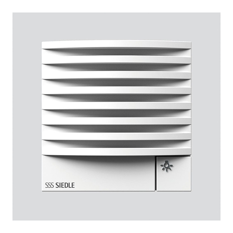
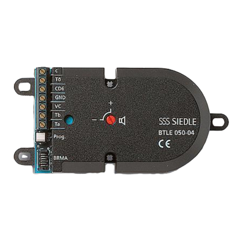
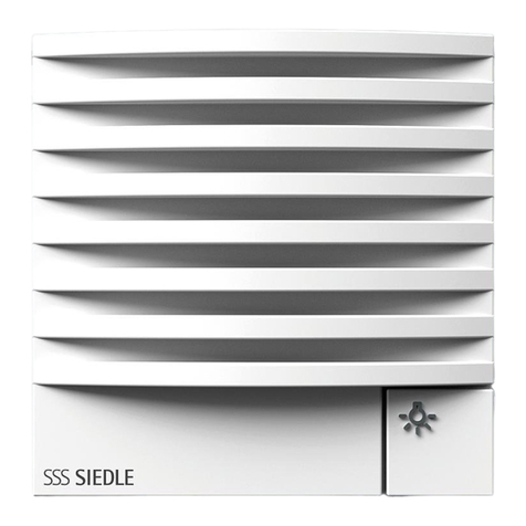
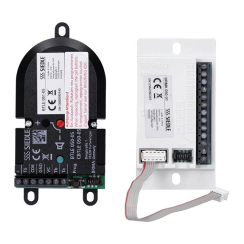
SSS Siedle BTLE 050-03 User manual

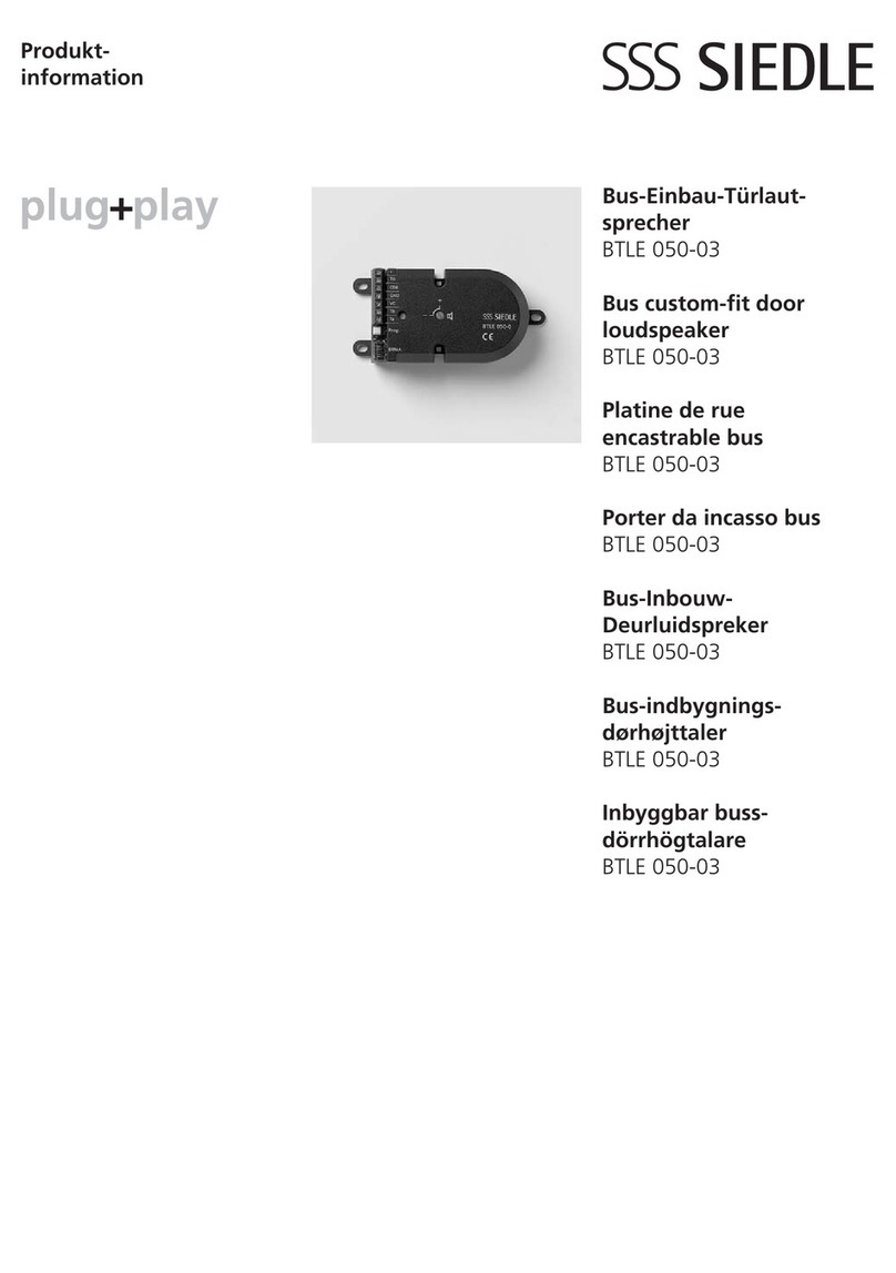
BTLE 050-03
Produktinformation
Bus-Einbau-
türlautsprecher
Product information
Bus custom-t
door loudspeaker
Information produit
Platine de rue
encastrable bus
Opuscolo informativo
sulprodotto
Porter da incasso bus
Productinformatie
Bus-Inbouw-
Deurluidspreker
Produktinformation
Bus-indbygnings-
dørhøjttaler
Produktinformation
Inbyggbar buss-
dörrhögtalare

5 6
BTLE 050-... 1. BRMA 050-... ... 14. BRMA 050-...
9
7
Prog.
8

2
71 mm
50 mm
3
1
31 mm
40 mm
100 mm
6,7 mm
4,7 mm
112 mm
60 mm
100 mm
53 mm 17 mm
7,65 mm
4,8 mm
85,3 mm
c
Mic
20 mm
70 mm
Ls
b
a
4

2
Anwendung
Bus-Einbautürlautsprecher
BTLE050‑03 für Siedle‑In‑Home‑Bus.
Für den Einbau in eine Briefkasten‑
anlage, Türkonstruktion, Frontplatte
etc.
Integrierter Türöffnerkontakt,
Schaltzeit Tö: 3Sekunden fest.
Anschluss von 12bauseitigen
Ruftasten über Schraubklemmen
an der Bus‑Ruftastenmatrix
BRMA050‑...
Max. 14Bus‑Ruftastenmatrizen
BRMA050‑... anschließbar; d.h. für
max. 160bauseitige Ruftasten.
Ansteuermöglichkeit für eine externe
Kamera mit dem BVS650‑... mög-
lich.
Universelle Befestigungsmöglich‑
keiten, bei Verwendung mit Jalousie
ZJ051‑... direkt auf dieser auf-
schraubbar.
1BTLE050‑... entspricht 2System‑
teilnehmern.
Elektrische Spannung
Einbau, Montage und Service‑
arbeiten elektrischer Geräte dürfen
ausschließlich durch eine Elektro‑
Fachkraft erfolgen.
Lieferumfang
• Bus-Einbautürlautsprecher
BTLE050‑03
• diese Produktinformation
Montage
1a Abmessungen des BTLE050‑...
1b Position von Mikrofon (Mic) und
Lautsprecher (Ls)
1c Abmessungen der Bus‑Ruf‑
tastenmatrix BRMA050‑... Die
Ruftastenmatrix kann mit dop‑
pelseitigem Klebeband oder mit
Schrauben im Gehäuse befestigt
werden.
2Montage in Briefkastenanlagen
mit Sprechfach. Die Frontplatte
muss abnehmbar, oder der Zugang
von hinten möglich sein. Bus‑
Einbautürlautsprecher hinter der
Einsprechöffnung (70x40mm oder
größer) mit den Befestigungslaschen
oder den Bohrungen montieren. Bei
zentraler Befestigung können die
Laschen abgebrochen werden, um
Platz zu sparen.
Hinweise
• Mikrofon und Lautsprecher
müssen bündig an der Sprech-
jalousie anliegen, damit keine
Rückkopplungen entstehen.
• Der BTLE050‑... darf nicht auf
den Gehäuseboden gelegt werden
und ist bauseits gegen evtl. eindrin-
gendes Wasser zu schützen.
Montage mit Jalousie ZJ051‑01
3 Durchbruch in der Frontplatte,
BxH 71x50mm
4 Jalousie einsetzen und befestigen.
5 Am BTLE050‑... die beiden
Befestigungsschrauben 2,9x22mm
durch die Schrauben 2,9x16mm
ersetzen, die der Jalousie beiliegen.
BTLE050‑... an der Jalousie fest‑
schrauben.
6 Elektret‑Mikrofon dicht an die
Frontplatte drücken.
Installation
Anschluss nach AS‑THa‑1/1, siehe
Rückseite dieser Produktinformation,
weitere Informationen im System‑
handbuch In‑Home‑Bus: Audio bzw.
Video.
Inbetriebnahme
7Lautstärkeregelung
Mit dem Potentiometer kann die
Lautstärke zur Tür verändert werden.
Bei akustischer Rückkopplung muss
die Lautstärke vom Türlautsprecher
zurückgenommen werden.
8 Die Taste „Prog.“ wird zur
Aktivierung des Prog.‑Mode benutzt.
Die Programmierung ist im
Systemhandbuch In‑Home‑Bus
beschrieben.
9 Anschluss der BRMA050‑... an
BTLE050‑...
Max. 14BRMA050‑... an einem
BTLE050‑... möglich.
Service
Gewährleistung im Rahmen der
gesetzlichen Bestimmungen.
Deutsch
Application
Bus custom‑t door loudspeaker
BTLE050‑03 for Siedle In‑Home bus.
For mounting in a letterbox system,
door construction, front panel etc.
Integrated door release contact,
door release switching time xed at
3seconds.
Connection of 12already existing
call buttons by means of screw‑type
terminals to the bus call button
matrix BRMA050‑...
Max. 14bus call button matrixes
BRMA050‑... can be connected;
i.e. for a maximum of 160 of the
customer’s own on‑site call buttons.
Facility for actuation of an external
camera possible with the BVS650‑...
Universal fastening possibilities,
when using with louvre ZJ051‑...
can be screwed on directly.
1BTLE050‑... corresponds to
2system users.
Electrical voltage
Mounting, installation and servicing
work on electrical devices may only
be performed by a suitably qualied
electrician.
Scope of supply
• Bus custom‑t door loudspeaker
BTLE050‑03
• This product information
Mounting
1a Dimensions of the BTLE050‑...
1b Position of microphone (Mic) and
loudspeaker (Ls)
1c Dimensions of the bus call button
matrix BRMA050‑... The call button
matrix can be xed in the housing
using double‑sided adhesive tape
or screws.
2Mounting in letterbox systems
with intercom compartment. The
front panel must be detachable or
alternatively access afforded from
behind. Mount the bus custom‑t
door loudspeaker behind the
intercom opening (70x40mm or
larger) using the fastening tabs or
English

3
holes. If fastened centrally, the tabs
can be broken off to save space.
Remarks
• The microphone and louds-
peaker have to lie ush with
the intercom louvre to prevent
feedback.
• The BTLE050‑... must not be laid
on the housing oor and must be
protected by the user where neces-
sary against the ingress of water.
Mounting with louvre ZJ051‑01
3Breakthrough in the front panel,
WxH 71x50mm
4 Insert the louvre and fasten.
5 At the BTLE050‑... replace the
two fastening screws 2.9x22mm
by screws 2.9x16mm. These are
enclosed with the louvre. Fasten the
BTLE050‑... to the louvre.
6Press the Electret microphone tight
up against the front panel.
Installation
Connection in accordance with
AS‑THa‑1/1, see reverse of this pro-
duct information. For more detailed
information, see the system manual
In‑Home bus: Audio or Video.
Commissioning
7Volume control
Using the potentiometer, it is pos‑
sible to change the volume to the
door. If acoustic feedback occurs,
the volume of the door loudspeaker
must be turned down.
8The “Prog.” button is used to acti‑
vate the programming mode.
Programming is described in the
system manual In‑Home bus.
9 Connection of the BRMA050‑... to
BTLE050‑...
A maximum of 14BRMA050‑...
units can be connected to one
BTLE050‑...
Servicing
Statutory warranty conditions apply.
Application
Platine de rue encastrable bus
BTLE050‑03 pour bus Siedle‑In‑
Home.
Pour montage dans une installation
de boîtes aux lettres, construction de
porte, façade etc.
Contact de gâche intégré, temps de
commutation Tö 3secondes, xe.
Raccordement de 12touches
d’appel présentes sur site, par
l’intermédiaire de bornes à vis, sur
la matrice de touches d’appel bus
BRMA050‑...
Possibilité de raccorder jusqu’à
14matrices de touches d’appel bus
BRMA050‑...; C’est‑à‑dire pour
max. 160touches d’appel sur site.
Possibilité de commander une
caméra externe avec le BVS650‑...
Possibilités de xation universelles
ou, lorsque l’on utilise la grille
ZJ051‑..., vissable directement sur
celle‑ci.
1BTLE050‑... correspond à
2adresses système.
Tension électrique
L’installation, le montage et l’entre-
tien d’appareils électriques ne
doivent être réalisés que par un spé-
cialiste en électricité.
Etendue de la fourniture
• Platine de rue encastrable bus
BTLE050‑03
• La présente information produit
Montage
1a Dimensions de la BTLE050‑...
1b Position du microphone (Mic) et
du haut‑parleur (Ls)
1c Dimensions de la matrice de
touches d’appel bus BRMA050‑...
La matrice de touches d’appel peut
être xée dans le boîtier à l’aide d’un
ruban adhésif double face ou de vis.
2Montage dans des installations
de boîtes aux lettres avec comparti‑
ment interphonique. La façade doit
pouvoir être déposée, ou bien il doit
pouvoir être possible d’y accéder
par l’arrière. Monter la platine de
rue encastrable bus derrière l’orice
interphonique (70x40mm ou plus
grand), à l’aide des pattes de xation
ou des perçages. En cas de xation
centrale, il est possible de rompre les
pattes, an de gagner de la place.
Remarques
• Le microphone et le haut-
parleur doivent afeurer sur la
grille interphonique, an qu’il n’y
ait pas de rétroactions.
• Le BTLE050‑... ne doit pas être
posé sur le fond du boîtier et il doit
être protégé par le client contre
toute pénétration éventuelle d’eau.
Montage avec grille ZJ051‑01
3 Percée dans la façade,
LxH 71x50mm
4 Mettre la grille en place et la xer.
5 Sur la BTLE050‑..., remplacer les
deux vis de xation 2,9x22mm par
les vis 2,9x16mm qui sont jointes
à la grille. Visser la BTLE050‑... sur
la grille.
6 Faire parfaitement plaquer le
microphone Elektret contre la
façade.
Installation
Raccordement selon AS‑THa‑1/1,
voir verso de cette information
produit, informations complémen-
taires dans le manuel système Bus
In‑Home: Audio ou Vidéo.
Mise en service
7 Réglage du volume
Le potentiomètre permet de modi‑
er le volume allant à la porte. En
cas de rétroaction acoustique, il faut
diminuer le volume de la platine
de rue.
8La touche «Prog.» est utilisée
pour activer le mode prog. (pro‑
grammation)
La programmation est décrite dans
le manuel système Bus In‑Home.
9 Raccordement de la BRMA050‑...
à la BTLE050‑...
Max. 14BRMA050‑... sur une
BTLE050‑... sont possibles.
Service
Garantie dans le cadre des disposi-
tions légales.
Français
4
Impiego
Porter da incasso bus BTLE050‑03
per Siedle‑In‑Home‑Bus.
Ideale da installare in un impianto
con cassetta per le lettere, in un
impianto citofonico, in un frontalino,
ecc.
Contatto apriporta integrato,
tempo di commutazione apriporta
3secondi ssi.
Collegamento di 12tasti di chiamata
predisposti in loco mediante morsetti
a vite alla matrice di tasti di chiamata
bus BRMA050‑...
Possono essere collegate al massimo
14matrici di tasti di chiamata bus
BRMA050‑...per ottenere un mas-
simo di 160tasti di chiamata predi-
sposti in loco.
Possibilità di comando di una teleca-
mera esterna con il BVS650‑...
Possibilités de xation universelles
ou, lorsque l’on utilise la grille
ZJ051‑..., vissable directement sur
celle‑ci.
1BTLE050‑... corrisponde a 2utenti
di sistema.
Tensione elettrica
Gli interventi di installazione, mon-
taggio e assistenza agli apparecchi
elettrici devono essere eseguiti esclu-
sivamente da elettricisti specializzati.
Kit di fornitura
• porter da incasso bus BTLE050‑03
• il presente opuscolo informativo
sul prodotto
Montaggio
1a Dimensioni del BTLE050‑...
1b Posizione del microfono (Mic) e
dell’altoparlante (Ls)
1c Dimensioni della matrice di tasti
di chiamata bus BRMA050‑... La
matrice di tasti di chiamata può
essere ssata nella scatola con
nastro biadesivo oppure con viti.
2Montaggio in impianti con
cassetta per le lettere dotati di
scomparto citofonico. Prelevare il
frontalino oppure prevedere una via
d’accesso dal retro. Montare il porter
da incasso bus dietro l’apertura dello
comparto citofonico (70x40mm o
più grande) utilizzando le linguette
di ssaggio oppure praticando appo‑
siti fori. In caso di ssaggio centrale
è possibile staccare le linguette per
risparmiare spazio.
Avvertenze
• Il microfono e l’altoparlante
devono essere disposti a lo con
la griglia fonica per evitare feno-
meni di ritorno acustico.
• Il BTLE050‑... non deve essere col
locato sul fondo della scatola e deve
essere protetto a cura del cliente
contro l’eventuale inltrazione
d’acqua.
Montaggio con griglia ZJ051‑01
3Apertura nel frontalino,
(larg.xalt.) 71x50mm
4 Inserire e ssare la griglia.
5 Sul BTLE050‑... sostituire le due
viti di ssaggio 2,9x22mm con le
viti 2,9x16mm fornite in dotazione
con la griglia. Avvitare il BTLE050‑...
alla griglia.
6Premere a tenuta il microfono ad
elettrete sul frontalino.
Installazione
Collegamento secondo AS‑THa‑1/1,
vedere a tergo del presente opu-
scolo informativo sul prodotto; per
ulteriori informazioni si rimanda al
manuale del sistema In‑Home‑Bus:
Audio oppure Video.
Messa in funzione
7 Regolazione del volume
Il potenziometro consente di modi‑
care il volume nel posto esterno.
In caso di ritorno acustico, occorre
ridurre il volume dal porter.
8Il tasto «Prog.» si utilizza per atti‑
vare la modalità programmazione.
La programmazione è descritta nel
manuale del sistema In‑Home‑Bus.
9 Collegamento della BRMA050‑...
al BTLE050‑...
È possibile collegare al massimo
14BRMA050‑... ad un BTLE050‑...
Assistenza
Prestazioni in garanzia nell’ambito
delle disposizioni previste per legge.
Italiano
Toepassing
Bus‑Deurluidspreker‑Inbouw
BTLE050‑03 voor Siedle‑In‑
Home‑Bus.
Voor de inbouw in een brievenbus-
installatie, deurconstructie, front‑
paneel, etc.
Geïntegreerde deuropener, schakel-
td Tö 3seconden vast.
Aansluiting van 12lokale oproep-
toetsen via schroefklemmen op
de Bus‑Oproeptoetsen‑Matrix
BRMA050‑...
Max. 14Bus‑Oproeptoetsen‑
Matrixen BRMA050‑... aan te
sluiten; d.w.z. voor max. 160lokale
oproeptoetsen.
Aanstuurmogelkheden voor een
externe camera met de BVS650‑...
mogelk.
Universele bevestigingsmogelkheid,
b gebruik met jaloezie ZJ051‑...
direct op deze vast te schroeven.
1BTLE050‑... komt overeen met
2systeemtoestellen.
Elektrische spanning
Inbouw, montage en onderhouds-
werkzaamheden aan elektrische
apparaten mogen uitsluitend door
een elektro‑vakman worden uitge-
voerd.
Leveringsomvang
• Bus‑Inbouw‑Deurluidspreker
BTLE050‑03
• deze productinformatie
Montage
1a Afmetingen van de BTLE050‑...
1b Positie van microfoon (Mic) en
luidspreker (Ls)
1c Afmetingen van de Bus‑
Oproeptoetsen‑Matrix BRMA050‑...
De Oproeptoetsen‑Matrix kan
met dubbelzdig plakband of met
schroeven in de behuizing bevestigd
worden.
2Montage in brievenbusinstallaties
met spreekvak. Het frontpaneel
dient afneembaar, zonder toegang
vanaf de achterzde mogelk zn.
Bus‑Inbouw‑Deurluidspreker achter
de spreekopening (70x40mm of
Nederlands

5
groter) met de bevestigingspinnen
of de boringen monteren. B cen‑
trale bevestiging kunnen de pinnen
worden afgebroken, om plaats te
besparen.
Aanwzingen
• Microfoon en luid-spreker
moeten direct tegen de spreek-
jaloezie aanliggen, zodat geen
terugkoppelingen ontstaan.
• De BTLE050‑... mag niet op de
bodem van de behuizing worden
geplaatst en dient b de montage
tegen eventueel indringend water
te worden beschermd.
Montage met jaloezie ZJ051‑01
3 Doorbraak in het frontpaneel,
BxH 71x50mm
4 Jaloezie plaatsen en bevestigen.
5 Op de BTLE050‑... de beide
bevestigingsschroeven 2,9x22mm
vervangen door de schroeven
2,9x16mm, die b de jaloezie zn
meegeleverd. BTLE050‑... op de
jaloezie vastschroeven.
6 Electret‑microfoon dicht tegen het
frontpaneel drukken.
Installatie
Aansluiting volgens AS‑THa‑1/1, zie
achterzde van deze productinfor-
matie, verdere informatie in het sys-
teemhandboek In‑Home‑Bus: Audio
of Video.
Ingebruikname
7Volumeregeling
Met de potmeter kan het volume
b de deur veranderd worden. B
accoustische terugkoppeling dient
het volume van de deurluidspreker
te worden verminderd.
8 De toets “Prog.” wordt voor
het activeren van de Prog.‑Mode
gebruik.
Het programmeren wordt in het
systeemhandboek In‑Home‑Bus
beschreven.
9 Aansluiting van de BRMA050‑...
op de BTLE050‑...
Max. 14 BRMA050‑... op één
BTLE050‑... mogelk.
Service
Aansprakelkheid in het kader van
de wettelke bepalingen.
Anvendelse
Bus‑indbygningsdørhøjttaler
BTLE050‑03 til Siedle‑In‑Home‑
bussen.
Til indbygning i postkasseanlæg,
dørkonstruktion, frontplade etc.
Integreret døråbnerkontakt, aktive-
ringstid døråbner 3sekunder fast.
Tilslutning af 12eksisterende
opkaldstryk via skrueklemmer til bus‑
opkaldstrykmatrix BRMA050‑...
Der kan maks. tilsluttes 14bus‑
opkaldstrykmatrix BRMA050‑...;
dvs. maks. 160opkaldstryk.
Mulighed for styring af et eksternt
kamera med BVS650‑...
Fleksibel montage ved hjælp af
jalousi ZJ051‑..., der fastgøres
direkte på modulet.
1BTLE050‑... svarer til 2systema-
bonnenter.
Elektrisk spænding
Indbygning og montering af samt
servicearbejde på elektrisk materiel
må kun foretages af en aut. elinstal-
latør.
Leveringsomfang
• Bus‑indbygningsdørhøjttaler
BTLE050‑03
• Denne produktinformation
Montage
1a Mål på BTLE050‑...
1b Placering af mikrofon (Mic) og
højttaler (Ls).
1c Mål på bus‑opkaldstrykmatrix
BRMA050‑... Bus‑opkaldstryk‑
matrixen kan fastgøres i kabinettet
med dobbeltklæbende tape eller
med skruer.
2 Montage i postkasseanlæg for‑
beredt for højttaler. Frontpladen skal
være aftagelig, eller der skal være
adgang fra bagsiden. Bus‑indbyg‑
nings dør højttaleren monteres bag
forpladens højttalergrill (70x40mm
eller større) ved hjælp af montage‑
pladerne eller mon tagehuller. Ved
central fastgørelse kan laskerne
brydes af for at spare plads.
Bemærk
• Mikrofon og højttaler skal
ugte med forpladen, således at
der ikke opstår tilbagekobling.
• BTLE050‑... må ikke monteres
direkte på kabinettet og skal
beskyttes mod evt. indtrængende
vand.
Montage med jalousi ZJ051‑01
3 Hul i frontpladen,
bxh 71x50mm
4 Jalousien isættes og fastgøres.
5 På BTLE050‑... udskiftes de to
montageskruer 2,9x22mm med
skruerne 2,9x16mm, som følger
med jalousiet. BTLE050‑... skrues
fast på jalousien.
6Elektretmikrofonen trykkes helt ind
mod frontpladen.
Installation
Tilslutning ifølge AS‑THa‑1/1, se
bag siden af denne produktinfor‑
mation, yderligere oplysninger i
System håndbogen In‑Home‑bus:
Audio eller Video.
Ibrugtagning
7Lydstyrkeregulering
Lydstyrken til døren kan ændres med
potentiometret. Ved akustisk til‑
bagekobling skal der skrues ned for
lydstyrken fra dørhøjttaleren.
8Tasten »Prog.« anvendes til
aktive ring af Prog.‑Mode.
Programmeringen er beskrevet i
Systemhånd bogen til In‑Home‑bus.
9 Tilslutning af BRMA050‑... til
BTLE050‑...
Maks. mulighed for 14BRMA050‑...
til en BTLE050‑...
Service
Garantien følger lovens bestem-
melser.
Dansk

6
Användning
Infällbar buss‑dörrhögtalare
BTLE050‑03 för Siedle‑In‑Home‑
buss.
För monteringen i en brevlådsan-
läggning, dörrkonstruktion, front-
platta osv.
Integrerad dörröppningskontakt,
kopplingstid Tö: 3sekunder fast.
Anslutning av 12redan bentliga
anropsknappar till buss‑knappma-
trisen BRMA050‑... med hjälp av
skruvklämmor.
Kan anslutas till max. 14buss‑
anropsknappmatriser BRMA050‑...;
dvs. för max. 160redan bentliga
anropsknappar.
Med BVS650‑... är det möjligt att
styra en extern kamera.
Universella infästningsmöjligheter,
när den används med gallret
ZJ051‑..., kan den skruvas fast
direkt på det.
1BTLE050‑... motsvarar 2system-
deltagare.
Elektrisk spänning
Installation, montering och servicear-
beten på elektriska apparater får
utföras endast av behörig eltekniker.
Leveransomfång
• Inbyggbar buss‑dörrhögtalare
BTLE050‑03
• Denna produktinformation
Montage
1a Måtten till BTLE050‑...
1b Position för mikrofon (Mic) och
högtalare (Ls)
1c Måtten till buss‑knappmatrisen
BRMA050‑... Knappmatrisen kan
monteras i höljet med dubbelsidig
klisterremsa eller med skruvar.
2Montering i brevlådeanlägg‑
ning med utrymme för högtalare.
Frontplattan måste kunnas ta av eller
också måste den kunnas komma
åt bakifrån. Montera den inbygg‑
bara buss‑dörrhögtalaren bakom
öppningen för att tala (70x40mm
eller större) med hjälp av fästena
eller hålen. Om monteringen sker i
mitten, kan fästena brytas av för att
spara plats.
Hänvisningar
• Mikrofonen och högtalare
måste ligga plant mot gallret
för att tala, så att det inte uppstår
någon återkoppling.
• BTLE050‑... får inte läggas på höl-
jets botten och ska på installations‑
platsen skyddas mot eventuellt
inträngande vatten.
Montering med gallret ZJ051‑01
3Genombrott i frontplattan,
BxH 71x50mm
4 Sätt i gallret och sätt fast det.
5 På BTLE050‑..., ersätt de båda
xeringsskruvarna 2,9x22mm mot
skruvarna 2,9x16mm som följer
med gallret. Skruva fast BTLE050‑...
på gallret.
6 Tryck Elektret‑mikrofonen tätt mot
frontplattan.
Installation
Anslutning enligt AS‑THa‑1/1, se
baksidan av denna produktinforma-
tion, ytterligare upplysningar nns
i systemhand boken In‑Home‑buss:
Audio eller Video.
Idrifttagning
7 Reglering av ljudstyrkan
Ljudstyrkan för dörren kan ändras
med potentiometern. Vid akustisk
återkoppling måste dörrhögtalarens
ljudstyrka minskas.
8Knappen ”Prog.” används för att
aktivera prog.‑moduset.
Programmeringen beskrivs i system‑
handboken In‑Home‑buss.
9 Anslutning av BRMA050‑... till
BTLE050‑...
Max. 14BRMA050‑... kan anslutas
till en BTLE050‑...
Service
Garanti inom ramen av de lagliga
bestämmelserna.
Svenska

7

AS-THa-1/1
Gerätebedarf
Appliance requirement
Appareils nécessaires
Distinta materiali
Benodigde apparatuur
Komponentbehov
Apparatbehov
Hinweis
Note
Remarque
Avvertenza
Aanwijzingen
Bemærk
Hänvisningar
Ta Ta Ta TaTa
Tb Tb Tb Tb Tb
Tö
Tö 12 V AC
min. 20 Ohm
b
c
ERT
ERT
ERTERT ERT
Tb
Tö6
7.1
7.3
7.11
7.12
Li
Li
230 V AC
N
L1
7.2
Ta
BTLE
BRMA
b) a) c) c) c) c)
Gerätebedarf
Hinweise
Siedle
Einbautürlautsprecher
BTLE 050-...
BRMA 050-...
BNG 650-... BTS 850-... BTS 850-... BTC 850-... BTC 850-...
S. Siedle & Söhne
Telefon- und Telegrafenwerke OHG
Postfach 1155
78113 Furtwangen
Bregstraße 1
78120 Furtwangen
Telefon +49 7723 63-0
Telefax +49 7723 63-300
www.siedle.de
© 2006/10.13
Printed in Germany
Best. Nr. 0-1101/231992
Other manuals for BTLE 050-03
2
Table of contents
Other SSS Siedle Speakers manuals

SSS Siedle
SSS Siedle STLM 645-0 User manual

SSS Siedle
SSS Siedle ATLC/NG 670-0 User manual

SSS Siedle
SSS Siedle BTLE 050-03 User manual

SSS Siedle
SSS Siedle BTLE 051-03 User manual

SSS Siedle
SSS Siedle TLE 051-02 User manual

SSS Siedle
SSS Siedle BTLEP 051-0 User manual

SSS Siedle
SSS Siedle BTLE 051-05 User manual

SSS Siedle
SSS Siedle STLM/TK 611-0 User manual

SSS Siedle
SSS Siedle TLE 061-01 User manual

SSS Siedle
SSS Siedle TLE 061-01 User manual