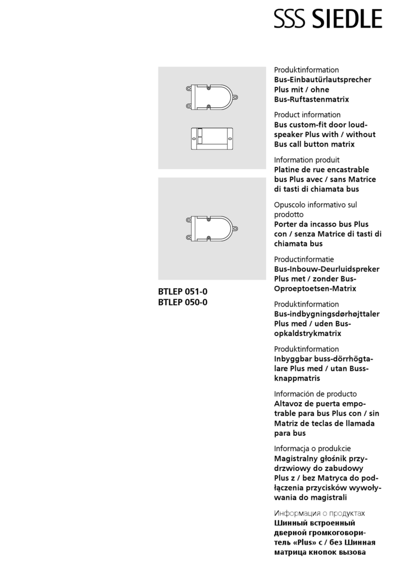
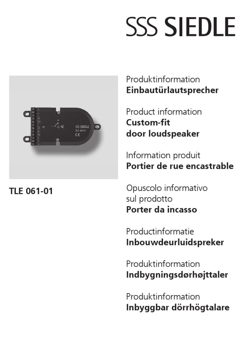
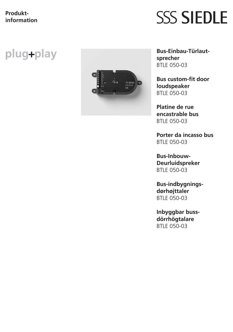
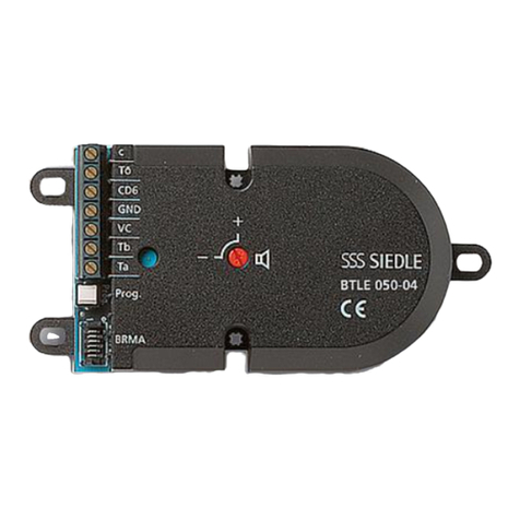
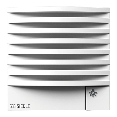
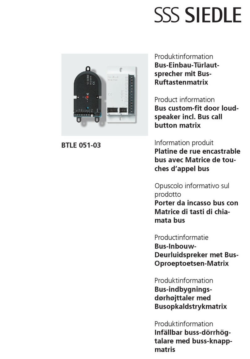
SSS Siedle BTLE 051-05 User manual

Produktinformation
Bus-Einbautürlautsprecher
mit / ohne
Bus-Ruftastenmatrix
Product information
Bus custom-t door loud-
speaker with / without
Bus call button matrix
Information produit
Platine de rue encastrable
bus avec / sans Matrice di
tasti di chiamata bus
Opuscolo informativo
sulprodotto
Porter da incasso bus
con / senza Matrice di
tasti di chiamata bus
Productinformatie
Bus-Inbouw-Deurluid-
spreker met / zonder Bus-
Oproeptoetsen-Matrix
Produktinformation
Bus-indbygningsdør højttaler
med / uden
Bus-opkaldstrykmatrix
Produktinformation
Inbyggbar buss-dörr-
högtalare med / utan
Buss-knappmatris
Información de producto
Altavoz de puerta en ins-
talaciones personalizadas,
para bus. con / sin Matriz de
teclas de llamada para bus
Informacja o produkcie
Magistralny głośnik przy-
drzwiowy do zabudowy
z / bez Matryca do pod-
łączenia przycisków wywoły-
wania do magistrali
Информация о продуктах
Шинный встроенный
дверной громкоговоритель
с / без Шинная матрица
кнопок вызова
BTLE 051-05
BTLE 050-05

71 mm
50 mm
3 4
2
1
31 mm
40 mm
100 mm
6,7 mm
4,7 mm
112 mm
60 mm
Mic
20 mm
70 mm
Ls
100 mm
53 mm 17 mm
7,65 mm
4,8 mm
85,3 mm
cb
a

56
7
Prog.
8
BTLE 050-... 1. BRMA 050-... ... 14. BRMA 050-...
9

2
Zusätzlich läßt sich der Prog.-Mode
durch 4 Sek. drucken der obersten
Klingeltaste aktivieren.
9 Anschluss der BRMA050-… an
BTLE050-…
Max. 14BRMA050-… an einem
BTLE050-… möglich.
Technische Daten BTLE 051-…
Kontaktart: 2Schließer 15VAC,
30VDC, 2A
Schaltzeit: 3Sek.
Schutzart: abhängig von den
Einbaubedingungen
Abmessungen (mm) BxHxT:
BTLE050-04124x60x31,
BRMA050-0153x100x17
Abmessungen Gehäuse (mm)
BxHxT: 100x60x31
Technische Daten BTLE 050-…
Schutzart: abhängig von den
Einbaubedingungen
Abmessungen (mm) BxHxT:
124x60x31
Abmessungen Gehäuse (mm)
BxHxT: 100x60x31
Deutsch
Anwendung
Bus-Einbautürlautsprecher mit
Bus-Ruftastenmatrix zum Einbau
in bauseits gestellte Sprechfächer,
Türkonstruktionen, Briefkästen etc.
An der Bus-Ruftastenmatrix
BRMA050-… können bis zu 12
bauseitige Ruftasten direkt ange-
schlossen werden.
Leistungsmerkmale:
• Lautsprecher, Sprachlautstärke
einstellbar
• langlebiges Elektret-Mikrofon
• potentialfreier Arbeitskontakt für
Türöffner, ohne Zusatzverdrahtung
über vorhandene Busleitung ansteu-
erbar
• integrierte Kameraansteuerung
• universelle Befestigungsmöglich-
keiten, bei Verwendung der
Jalousie ZJ051-… direkt auf dieser
anschraubbar
1BTLE050-… entspricht
2Systemteilnehmern.
Elektrische Spannung
Einbau, Montage und Service-
arbeiten elektrischer Geräte dürfen
ausschließlich durch eine Elektro-
Fachkraft erfolgen.
Lieferumfang BTLE 051-…
• Bus-Einbautürlautsprecher
BTLE050-…
• Bus-Ruftastenmatrix BRMA050-…
• diese Produktinformation
Lieferumfang BTLE 050-…
• Bus-Einbautürlautsprecher
BTLE050-…
• diese Produktinformation
Montage
1a Abmessungen des BTLE050-…
1b Position von Mikrofon (Mic) und
Lautsprecher (Ls)
1c Abmessungen der Bus-Ruftasten-
matrix BRMA050-…
Die Ruftastenmatrix kann mit dop-
pelseitigem Klebeband oder mit
Schrauben im Gehäuse befestigt
werden.
2 Montage in Briefkastenanlagen
mit Sprechfach. Die Frontplatte
muss abnehmbar, oder der Zugang
von hinten möglich sein. Bus-
Einbautürlautsprecher hinter der
Einsprechöffnung (70x40mm oder
größer) mit den Befestigungslaschen
oder den Bohrungen montieren. Bei
zentraler Befestigung können die
Laschen abgebrochen werden, um
Platz zu sparen.
Hinweise
• Mikrofon und Lautsprecher
müssen bündig an der Sprech-
jalousie anliegen, damit keine
Rückkopplungen entstehen.
• Der BTLE050-… darf nicht auf
den Gehäuseboden gelegt werden
und ist bauseits gegen evtl. eindrin-
gendes Wasser zu schützen.
Montage mit Jalousie ZJ051-01
3 Durchbruch in der Frontplatte,
BxH 71x50mm
4 Jalousie einsetzen und befestigen.
5 Am BTLE050-… die beiden
Befestigungsschrauben 2,9x22mm
durch die Schrauben 2,9x16mm
ersetzen, die der Jalousie beiliegen.
BTLE050-… an der Jalousie fest-
schrauben.
6 Elektret-Mikrofon dicht an die
Frontplatte drücken.
Installation
Installation, Inbetriebnahme und
Programmierung ist im ent-
sprechenden Systemhandbuch
beschrieben und liegt dem Netzgerät
bzw. Server bei.
Inbetriebnahme
7 Lautstärkeregelung
Mit dem Potentiometer kann die
Lautstärke zur Tür verändert werden.
Bei akustischer Rückkopplung muss
die Lautstärke vom Türlautsprecher
zurückgenommen werden.
8 Die Taste „Prog.“ wird zur
Aktivierung des Prog.-Mode benutzt.
Die Programmierung ist im System-
handbuch In-Home-Bus beschrieben.

3
Application
Bus custom-t door loudspeaker
with bus call button matrix for instal-
lation in the customer’s intercom
compartments, door constructions,
letterboxes, etc.
Up to 12 of the customer’s call but-
tons can be directly connected to
the BRMA050-… bus call button
matrix.
Performance features:
• Loudspeaker, voice volume can be
adjusted
• Durable electret microphone
• Potential-free work contact for
door release, can be controlled
without additional wiring via existing
bus line
• Integrated camera actuation
• Universal fastening options, when
used with the ZJ051-… grille, it can
be screwed onto this directly
1BTLE050-… corresponds to
2system users.
Electrical voltage
Mounting, installation and servicing
work on electrical devices may only
be performed by a suitably qualied
electrician.
Scope of supply BTLE 051-…
• Bus custom-t door loudspeaker
BTLE050-…
• Bus call button matrix
BRMA050-…
• this product information
Scope of supply BTLE 050-…
• Bus custom-t door loudspeaker
BTLE050-…
• This product information
Mounting
1a Dimensions of the BTLE050-…
1b Position of microphone (Mic) and
loudspeaker (Ls)
1c Dimensions of the bus call button
matrix BRMA050-… The call button
matrix can be xed in the housing
using double-sided adhesive tape
or screws.
English
2 Mounting in letterbox systems
with intercom compartment. The
front panel must be detachable or
alternatively access afforded from
behind. Mount the bus custom-
t door loudspeaker behind the
intercom opening (70x40mm or
larger) using the fastening tabs or
holes. If fastened centrally, the tabs
can be broken off to save space.
Remarks
• The microphone and loud-
speaker have to lie ush with
the intercom louvre to prevent
feedback.
• The BTLE050-… must not be laid
on the housing oor and must be
protected by the user where neces-
sary against the ingress of water.
Mounting with louvre ZJ051-01
3 Breakthrough in the front panel,
WxH 71x50mm
4 Insert the louvre and fasten.
5 At the BTLE050-… replace the
two fastening screws 2.9x22mm
by screws 2.9x16mm. These are
enclosed with the louvre. Fasten the
BTLE050-… to the louvre.
6 Press the Electret microphone tight
up against the front panel.
Installation
Installation, commissioning and pro-
gramming are described in the rel-
evant system manual and enclosed
with the line rectier/server.
Commissioning
7 Volume control
Using the potentiometer, it is pos-
sible to change the volume to the
door. If acoustic feedback occurs,
the volume of the door loudspeaker
must be turned down.
8 The “Prog.” button is used to acti-
vate the programming mode.
Programming is described in the
system manual In-Home bus.
The programming mode can also
be activated by pressing the top bell
button for 4seconds.
9 Connection of the BRMA050-…
to BTLE050-…
A maximum of 14BRMA050-…
units can be connected to one
BTLE050-…
Specications BTLE 051-…
Contact type: 2contact 15VAC,
30VDC, 2A
Switching time: 3sec
Protection system: Dependent on
the mounting conditions
Dimensions (mm) WxHxD:
BTLE050-04124x60x31,
BRMA050-0153x100x17
Dimensions housing (mm)
WxHxD: 100x60x31
Specications BTLE 050-…
Protection system: Dependent on
the mounting conditions
Dimensions (mm) WxHxD:
124x60x31
Dimensions housing (mm)
WxHxD: 100x60x31

4
Application
Haut-parleur de porte bus encas-
trable avec matrice de touches
d’appel bus pour montage dans des
modules de communication, des
constructions de portes, des boîtes
aux lettres, etc. fournis par le client.
Jusqu’à 12 touches d’appel sur site
peuvent être directement connectées
à la matrice de touches d’appel bus
BRMA050-…
Caractéristiques fonctionnelles:
• Haut-parleur, volume de la voix
réglable
• Microphone electret d’une grande
durée de vie
• Contact de travail sans potentiel
pour gâche, sans câblage supplé-
mentaire activable via ligne bus
existante
• Commande de caméra intégrée
• Possibilités de xation universelles ;
en cas d’utilisation de la grille
ZJ051-…, se visse directement sur
celle-ci
1BTLE050-… correspond à
2adresses système.
Tension électrique
L’installation, le montage et l’entre-
tien d’appareils électriques ne
doivent être réalisés que par un
spécialiste en électricité.
Etendue de la fourniture
BTLE 051-…
• Platine de rue encastrable bus
BTLE050-…
• Matrice de touches d’appel bus
BRMA050-…
• La présente information produit
Etendue de la fourniture
BTLE 050-…
• Platine de rue encastrable bus
BTLE050-…
• La présente information produit
Montage
1a Dimensions de la BTLE050-…
1b Position du microphone (Mic) et
du haut-parleur (Ls)
Français
1c Dimensions de la matrice de
touches d’appel bus BRMA050-…
La matrice de touches d’appel peut
être xée dans le boîtier à l’aide d’un
ruban adhésif double face ou de vis.
2 Montage dans des installations
de boîtes aux lettres avec comparti-
ment interphonique. La façade doit
pouvoir être déposée, ou bien il doit
pouvoir être possible d’y accéder
par l’arrière. Monter la platine de
rue encastrable bus derrière l’orice
interphonique (70x40mm ou plus
grand), à l’aide des pattes de xation
ou des perçages. En cas de xation
centrale, il est possible de rompre les
pattes, an de gagner de la place.
Remarques
• Le microphone et le haut-
parleur doivent afeurer sur la
grille interphonique, an qu’il n’y
ait pas de rétroactions.
• Le BTLE050-… ne doit pas être
posé sur le fond du boîtier et il doit
être protégé par le client contre
toute pénétration éventuelle d’eau.
Montage avec grille ZJ051-01
3 Percée dans la façade,
LxH 71x50mm
4 Mettre la grille en place et la xer.
5 Sur la BTLE050-…, remplacer les
deux vis de xation 2,9x22mm par
les vis 2,9x16mm qui sont jointes
à la grille. Visser la BTLE050-… sur
la grille.
6 Faire parfaitement plaquer le
microphone Elektret contre la
façade.
Installation
L’installation, la mise en service et la
programmation sont décrites dans le
manuel système correspondant, qui
est joint au bloc d’alimentation et
au serveur.
Mise en service
7 Réglage du volume
Le potentiomètre permet de modi-
er le volume allant à la porte. En
cas de rétroaction acoustique, il faut
diminuer le volume de la platine
de rue.
8 La touche “Prog.” est utilisée pour
activer le mode prog. (program-
mation)
La programmation est décrite dans
le manuel système Bus In-Home.
Le mode prog. peut en outre être
activé en appuyant sur la touche
de sonnerie supérieur pendant 4
secondes.
9 Raccordement de la BRMA050-…
à la BTLE050-…
Max. 14BRMA050-… sur une
BTLE050-… sont possibles.
Caractéristiques techniques
BTLE051-…
Type de contact : 2 contacts de
travail 15VAC, 30VDC, 2A
Temps de commutation : 3s
Indice de protection : en fonction
des conditions de montage
Dimensions (mm) lxHxP :
BTLE050-04124x60x31,
BRMA050-0153x100x17
Dimensions boîtier (mm) lxHxP :
100x60x31
Caractéristiques techniques
BTLE050-…
Indice de protection : en fonction
des conditions de montage
Dimensions (mm) lxHxP :
124x60x31
Dimensions boîtier (mm) lxHxP :
100x60x31
5
Impiego
Porter da incasso bus con matrice di
tasti di chiamata bus da installare in
scomparti citofonici, impianti cito-
fonici, cassette per le lettere, ecc.,
predisposti a cura del cliente.
Alla matrice di tasti di chiamata bus
BRMA050-… è possibile collegare
direttamente no a 12 tasti di chia-
mata predisposti a cura del cliente.
Prestazioni:
• Altoparlante, volume regolabile
• Microfono ad elettrete di lunga
durata
• Contatto di lavoro a potenziale
zero per apriporta, attivabile senza
cablaggio supplementare tramite
linea bus presente
• Comando telecamera integrato
• Possibilità di ssaggio universali;
se si utilizza la griglia ZJ051-… può
essere avvitato direttamente su di
essa
1BTLE050-… corrisponde a 2utenti
di sistema.
Tensione elettrica
Gli interventi di installazione, mon-
taggio e assistenza agli apparecchi
elettrici devono essere eseguiti esclu-
sivamente da elettricisti specializzati.
Kit di fornitura BTLE051-…
• Porter da incasso bus BTLE050-…
• Matrice di tasti di chiamata bus
BRMA050-…
• il presente opuscolo informativo
sul prodotto
Kit di fornitura BTLE050-…
• porter da incasso bus BTLE050-…
• il presente opuscolo informativo
sul prodotto
Montaggio
1a Dimensioni del BTLE050-…
1b Posizione del microfono (Mic) e
dell’altoparlante (Ls)
1c Dimensioni della matrice di tasti
di chiamata bus BRMA050-…
La matrice di tasti di chiamata può
essere ssata nella scatola con
nastro biadesivo oppure con viti.
Italiano
2 Montaggio in impianti con
cassetta per le lettere dotati di
scomparto citofonico. Prelevare il
frontalino oppure prevedere una via
d’accesso dal retro. Montare il porter
da incasso bus dietro l’apertura dello
comparto citofonico (70x40mm o
più grande) utilizzando le linguette
di ssaggio oppure praticando appo-
siti fori. In caso di ssaggio centrale
è possibile staccare le linguette per
risparmiare spazio.
Avvertenze
• Il microfono e l’altoparlante
devono essere disposti a lo con
la griglia fonica per evitare feno-
meni di ritorno acustico.
• Il BTLE050-… non deve essere col
locato sul fondo della scatola e deve
essere protetto a cura del cliente
contro l’eventuale inltrazione
d’acqua.
Montaggio con griglia ZJ051-01
3 Apertura nel frontalino,
(larg.xalt.) 71x50mm
4 Inserire e ssare la griglia.
5 Sul BTLE050-… sostituire le due
viti di ssaggio 2,9x22mm con le
viti 2,9x16mm fornite in dotazione
con la griglia. Avvitare il BTLE050-…
alla griglia.
6 Premere a tenuta il microfono ad
elettrete sul frontalino.
Installazione
L’installazione, la messa in funzione
e la programmazione sono descritte
nel corrispondente manuale allegato
all’alimentatore o al server.
Messa in funzione
7 Regolazione del volume
Il potenziometro consente di modi-
care il volume nel posto esterno.
In caso di ritorno acustico, occorre
ridurre il volume dal porter.
8 Il tasto “Prog.” si utilizza per atti-
vare la modalità programmazione.
La programmazione è descritta nel
manuale del sistema In-Home-Bus.
Inoltre, la modalità programmazione
è attivabile premendo per 4 secondi
il tasto campanello più in alto.
9 Collegamento della BRMA050-…
al BTLE050-…
È possibile collegare al massimo
14BRMA050-… ad un BTLE050-…
Dati tecnici BTLE051-…
Tipo di contatto: 2 contatti nor-
malmente aperti max. 15VAC,
30VDC, 2A
Tempo di attivazione: 3sec.
Tipo di protezione: in funzione delle
condizioni di montaggio
Dimensioni (mm) Larg.xAlt.xProf.:
BTLE050-04124x60x31,
BRMA050-0153x100x17
Dimensioni scatola (mm)
Larg.xAlt.xProf.: 100x60x31
Dati tecnici BTLE050-…
Tipo di protezione: in funzione delle
condizioni di montaggio
Dimensioni (mm) Larg.xAlt.xProf.:
124x60x31
Dimensioni scatola (mm)
Larg.xAlt.xProf.: 100x60x31

6
Toepassing
Bus-inbouwdeurluidspreker met
bus-oproeptoetsenmatrix voor de
inbouw in lokaal geplaatste spreek-
vakken, deurconstructies, brieven-
bussen etc.
Op de bus-oproeptoetsenmatrix
BRMA050-… kunnen tot maximaal
12 lokale oproeptoetsen direct
worden aangesloten.
Prestatiekenmerken:
• Luidspreker, spraakvolume instel-
baar
• Duurzame elektret-microfoon
• Potentiaalvr werkcontact voor
deuropener, zonder additionele
bekabeling via bestaande busleiding
aan te sturen
• Geïntegreerde camera-aansturing
• Universele bevestigingsmogelk-
heden, b gebruik van de jaloezie
ZJ051-… direct op deze vast te
schroeven
1BTLE050-… komt overeen met
2systeemtoestellen.
Elektrische spanning
Inbouw, montage en onderhouds-
werkzaamheden aan elektrische
apparaten mogen uitsluitend door
een elektro-vakman worden uitge-
voerd.
Leveringsomvang BTLE 051-…
• Bus-Inbouw-Deurluidspreker
BTLE050-…
• Bus-Oproeptoetsen-Matrix
BRMA050-…
• deze productinformatie
Leveringsomvang BTLE 050-…
• Bus-Inbouw-Deurluidspreker
BTLE050-…
• deze productinformatie
Montage
1a Afmetingen van de BTLE050-…
1b Positie van microfoon (Mic) en
luidspreker (Ls)
1c Afmetingen van de Bus-
Oproeptoetsen-Matrix BRMA050-…
De Oproeptoetsen-Matrix kan
met dubbelzdig plakband of met
Nederlands
schroeven in de behuizing bevestigd
worden.
2 Montage in brievenbusinstallaties
met spreekvak. Het frontpaneel
dient afneembaar, zonder toegang
vanaf de achterzde mogelk zn.
Bus-Inbouw-Deurluidspreker achter
de spreekopening (70x40mm of
groter) met de bevestigingspinnen
of de boringen monteren. B cen-
trale bevestiging kunnen de pinnen
worden afgebroken, om plaats te
besparen.
Aanwzingen
• Microfoon en luid-spreker
moeten direct tegen de spreek-
jaloezie aanliggen, zodat geen
terugkoppelingen ontstaan.
• De BTLE050-… mag niet op de
bodem van de behuizing worden
geplaatst en dient b de montage
tegen eventueel indringend water te
worden beschermd.
Montage met jaloezie ZJ051-01
3 Doorbraak in het frontpaneel,
BxH 71x50mm
4 Jaloezie plaatsen en bevestigen.
5 Op de BTLE050-… de beide
bevestigingsschroeven 2,9x22mm
vervangen door de schroeven
2,9x16mm, die b de jaloezie zn
meegeleverd. BTLE050-… op de
jaloezie vastschroeven.
6 Electret-microfoon dicht tegen het
frontpaneel drukken.
Installatie
Installatie, ingebruikname en pro-
grammering zn in het betreffende
systeemhandboek beschreven en
zn meegeleverd b de netvoeding
resp. server.
Ingebruikname
7 Volumeregeling
Met de potmeter kan het volume
b de deur veranderd worden. B
accoustische terugkoppeling dient
het volume van de deurluidspreker
te worden verminderd.
8 De toets „Prog.” wordt voor
het activeren van de Prog.-Mode
gebruik.
Het programmeren wordt in het
systeemhandboek In-Home-Bus
beschreven.
Additioneel is de programmeer-
modus te activeren door 4 seconden
op de bovenste beltoets te drukken.
9 Aansluiting van de BRMA050-…
op de BTLE050-…
Max. 14 BRMA050-… op één
BTLE050-… mogelk.
Technische gegevens BTLE051-…
Contacttype: 2 sluitcontacten
15VAC, 30VDC, 2A
Schakeltd: 3sec.
Beschermingsklasse: afhankelk van
de inbouwbepalingen
Afmetingen (mm) BxHxD:
BTLE050-04124x60x31,
BRMA050-0153x100x17
Afmeting behuizing (mm) BxHxD:
100x60x31
Technische gegevens BTLE050-…
Beschermingsklasse: afhankelk van
de inbouwbepalingen
Afmetingen (mm) BxHxD:
124x60x31
Afmeting behuizing (mm) BxHxD:
100x60x31

7
Anvendelse
Bus-indbygningsdørhøjttaler med
bus-opkaldstastmatrix til indbygning
i samtalekabinetter, dørkonstruk-
tioner, postkasser etc. på installati-
onsstedet.
På bus-opkaldstastmatrix
BRMA050-… kan op til 12 opkalds-
taster tilsluttes direkte på installati-
onsstedet.
Specikationer:
• Højttaler, voice volume indstillelig
• Elektret-mikrofon med lang levetid
• Potentialfri arbejdskontakt til dør-
åbner, kan trigges over eksisterende
busledning uden ekstra fortrådning
• Integreret kamerastyring
• Universelle monteringsmuligheder,
kan ved brug af jalousi ZJ051-…
skrues direkte på dette
1BTLE050-… svarer til 2systema-
bonnenter.
Elektrisk spænding
Indbygning og montering af samt
servicearbejde på elektrisk materiel
må kun foretages af en aut. elinstal-
latør.
Leveringsomfang BTLE051-…
• Bus-indbygningsdørhøjttaler
BTLE050-…
• Bus-opkaldstrykmatrix
BRMA050-…
• Denne produktinformation
Leveringsomfang BTLE050-…
• Bus-indbygningsdørhøjttaler
BTLE050-…
• Denne produktinformation
Montage
1a Mål på BTLE050-…
1b Placering af mikrofon (Mic) og
højttaler (Ls).
1c Mål på bus-opkaldstrykmatrix
BRMA050-… Bus-opkaldstryk-
matrixen kan fastgøres i kabinettet
med dobbeltklæbende tape eller
med skruer.
Dansk
2 Montage i postkasseanlæg for-
beredt for højttaler. Frontpladen
skal være aftagelig, eller der skal
være adgang fra bagsiden. Bus-
indbygningsdørhøjttaleren mon-
teres bag forpladens højttalergrill
(70x40mm eller større) ved hjælp
af montagepladerne eller montage-
huller. Ved central fastgørelse kan
laskerne brydes af for at spare plads.
Bemærk
• Mikrofon og højttaler skal
ugte med forpladen, således at
der ikke opstår tilbagekobling.
• BTLE050-… må ikke monteres
direkte på kabinettet og skal
beskyttes mod evt. indtrængende
vand.
Montage med jalousi ZJ051-01
3 Hul i frontpladen,
bxh 71x50mm
4 Jalousien isættes og fastgøres.
5 På BTLE050-… udskiftes de to
montageskruer 2,9x22mm med
skruerne 2,9x16mm, som følger
med jalousiet. BTLE050-… skrues
fast på jalousien.
6 Elektretmikrofonen trykkes helt
ind mod frontpladen.
Installation
Installation, ibrugtagning og pro-
grammering er beskrevet i den tilhø-
rende systemhåndbog og er vedlagt
strømforsyningen eller serveren.
Ibrugtagning
7 Lydstyrkeregulering
Lydstyrken til døren kan ændres med
potentiometret. Ved akustisk tilba-
gekobling skal der skrues ned for
lydstyrken fra dørhøjttaleren.
8 Tasten ”Prog.” anvendes til aktive-
ring af Prog.-Mode.
Programmeringen er beskrevet i
Systemhåndbogen til In-Home-bus.
Prog.-Mode kan også aktiveres ved
at trykke på den øverste ringetast
i 4 sek.
9 Tilslutning af BRMA050-… til
BTLE050-…
Maks. mulighed for
14BRMA050-… til en BTLE050-…
Tekniske specikationer
BTLE051-…
Kontakttype: afhankelijk van
de inbouwbepalingen
Koblingstid: 3sek.
Kapslingsklasse: Afhængigt af
indbygningsbetingelserne
Mål (mm) bxhxd:
BTLE050-04124x60x31,
BRMA050-0153x100x17
Mål dåse (mm) bxhxd:
100x60x31
Tekniske specikationer
BTLE050-…
Kapslingsklasse: Afhængigt af
indbygningsbetingelserne
Mål (mm) bxhxd: 124x60x31
Mål dåse (mm) bxhxd:
100x60x31

8
Användning
Infällbar buss-dörrhögtalare med
buss-knappmatris för montering i
redan bentliga högtalarutrymmen,
dörrkonstruktioner, brevlådor osv.
På buss-knappmatrisen
BRMA050-… kan upp till 12 redan
bentliga anropsknappar anslutas
direkt.
Egenskaper:
• Högtalare, ljudstyrkan för talet kan
ställas in
• Elektret-mikrofon med lång
brukstid
• Potentialfri arbetskontakt för
dörröppnare, kan styras via redan
bentlig buss-ledare utan extra led-
ningsdragning
• Integrerad kamerastyrning
• Universella xeringsmöjligheter,
kan vid behov skruvas fast direkt på
gallret ZJ051-…
1BTLE050-… motsvarar 2system-
deltagare.
Elektrisk spänning
Installation, montering och servicear-
beten på elektriska apparater får
utföras endast av behörig eltekniker.
Leveransomfång BTLE051-…
• Inbyggbar buss-dörrhögtalare
BTLE050-…
• Buss-knappmatris BRMA050-…
• Denna produktinformation
Leveransomfång BTLE050-…
• Inbyggbar buss-dörrhögtalare
BTLE050-…
• Denna produktinformation
Montage
1a Måtten till BTLE050-…
1b Position för mikrofon (Mic) och
högtalare (Ls)
1c Måtten till buss-knappmatrisen
BRMA050-… Knappmatrisen kan
monteras i höljet med dubbelsidig
klisterremsa eller med skruvar.
Svenska
2 Montering i brevlådeanlägg-
ning med utrymme för högtalare.
Frontplattan måste kunnas ta av eller
också måste den kunnas komma
åt bakifrån. Montera den inbygg-
bara buss-dörrhögtalaren bakom
öppningen för att tala (70x40mm
eller större) med hjälp av fästena
eller hålen. Om monteringen sker i
mitten, kan fästena brytas av för att
spara plats.
Hänvisningar
• Mikrofonen och högtalare
måste ligga plant mot gallret
för att tala, så att det inte uppstår
någon återkoppling.
• BTLE050-… får inte läggas på
höljets botten och ska på installa-
tionsplatsen skyddas mot eventuellt
inträngande vatten.
Montering med gallret ZJ051-01
3 Genombrott i frontplattan,
BxH 71x50mm
4 Sätt i gallret och sätt fast det.
5 På BTLE050-…, ersätt de båda
xeringsskruvarna 2,9x22mm mot
skruvarna 2,9x16mm som följer
med gallret. Skruva fast BTLE050-…
på gallret.
6 Tryck Elektret-mikrofonen tätt mot
frontplattan.
Installation
Installationen, idrifttagningen och
programmeringen beskrivs i den
beträffade systemhandboken, som
har bifogats nätadaptern alt. ser-
vern.
Idrifttagning
7 Reglering av ljudstyrkan
Ljudstyrkan för dörren kan ändras
med potentiometern. Vid akustisk
återkoppling måste dörrhögtalarens
ljudstyrka minskas.
8 Knappen ”Prog.” används för att
aktivera prog.-moduset.
Programmeringen beskrivs i system-
handboken In-Home-buss.
Genom att trycka på knappen Prog.-
Mode under 4 sek. aktiveras des-
sutom den översta ringknappen.
9 Anslutning av BRMA050-… till
BTLE050-…
Max. 14BRMA050-… kan anslutas
till en BTLE050-…
Tekniska data BTLE051-…
Typ av kontakt: 2 slutkontakter
15VAC, 30VDC, 2A
Kopplingstid: 3sek.
Skyddstyp: beroende på
monteringsförhållandena
Mått (mm) BxHxD:
BTLE050-04124x60x31,
BRMA050-0153x100x17
Mått hölje (mm) BxHxD:
100x60x31
Tekniska data BTLE050-…
Skyddstyp: beroende på
monteringsförhållandena
Mått (mm) BxHxD: 124x60x31
Mått hölje (mm) BxHxD:
100x60x31

9
Español
Puesta en servicio
7 Regulación de volumen
Con el potenciómetro se puede
modificar el volumen para la
puerta. En caso de pitidos deberá
restaurarse el volumen del altavoz
de puerta.
8 La tecla “Prog.“ se utiliza para
activar el modo de programación.
La programación se describe en el
manual del sistema del bus In-Home.
Además, el modo de programación
se puede activar pulsando el botón
de timbre superior durante
4 segundos.
9 Conexión de BRMA 050-... a
BTLE 050-...
Se pueden conectar como máximo
14 BRMA 050-... a un
BTLE 050-...
Características técnicas
BTLE051-…
Tipo de contactos: 2 contactos
normalmente abiertos 15VAC,
30VDC, 2A
Tiempo de actuación: 3seg.
Grado de protección: Dependiente
de las condiciones de montaje
Dimensiones (mm) AnxAlxPr:
BTLE050-04124x60x31,
BRMA050-0153x100x17
Dimensiones de carcasa (mm)
AnxAlxPr: 100x60x31
Características técnicas
BTLE050-…
Grado de protección: Dependiente
de las condiciones de montaje
Dimensiones (mm) AnxAlxPr:
124x60x31
Dimensiones de carcasa (mm)
AnxAlxPr: 100x60x31
Aplicación
Altavoz de puerta empotrable para
bus con matriz de teclas de llamada
para bus para el montaje en com-
partimentos de interfono del cliente,
construcciones de puerta, buzones,
etc.
En la matriz de teclas de llamada
para bus BRMA050-… se pueden
conectar directamente hasta
12teclas de llamada del cliente.
Características:
• Altavoz, volumen de voz ajustable
• Micrófono de electreto de larga
duración
• Contacto de trabajo libre de
potencial para abrepuertas, sin
cableado adicional activable a través
del cable de bus existente
• Activación de cámara integrado
• Posibilidades de jación universal,
si se usa con persiana ZJ051-… se
puede atornillar directamente a la
misma
1BTLE050-… corresponde a 2esta-
ciones de sistema.
Tensión eléctrica
La integración, montaje y los tra-
bajos de servicio en aparatos eléc-
tricos deben ser realizados exclusiva-
mente por electricistas
especializados.
Alcance de suministro
BTLE051-…
• Altavoz de puerta empotrable para
bus BTLE 050-...
• Matriz de teclas de llamada para
bus BRMA 050-...
• Esta información de producto
Alcance de suministro
BTLE050-…
• Altavoz de puerta empotrable para
bus BTLE 050-...
• Esta información de producto
Montaje
1a Dimensiones del BTLE 050-...
1b Posición del micrófono (Mic) y del
altavoz (Ls)
1c Dimensiones de la matriz de
teclas de llamada para bus
BRMA 050-... La matriz de teclas de
llamada puede jarse en la carcasa
con cinta adhesiva de doble cara o
con tornillos.
2 Montaje en sistemas de buzón
con compartimento de voz. El panel
frontal debe ser desmontable o se
debe poder acceder a él desde la
parte trasera. Montar el altavoz de
puerta empotrable para bus detrás
de la abertura para voz (70 x 40 mm
o más) utilizando las orejas de suje-
ción o los oricios. Para el montaje
central, las orejas pueden romperse
para ahorrar espacio.
Notas
• El micrófono y el altavoz deben
quedar apoyados enrasados
sobre la persiana del interfono
de tal modo que se produzcan aco-
plamientos de sonido.
• El BTLE 050-... no debe colocarse
en el fondo de la carcasa y el cliente
debe encargarse de protegerlo
contra la posible penetración de
agua.
Montaje con persiana ZJ 051-01
3 Abertura en el panel frontal,
ancho x alto 71 x 50 mm
4 Introducir y jar la persiana.
5 Sustituir los dos tornillos de
jación de 2,9 x 22 mm de la
BTLE 050-... por los tornillos de
2,9 x 16 mm suministrados con la
persiana. Atornillar el BTLE 050-... a
la persiana.
6 Presionar el micrófono de electreto
bien pegado al panel frontal.
Instalación
La instalación, la puesta en servicio
y la programación se describen en el
correspondiente manual del sistema
y se adjuntan a la fuente de alimen-
tación o bien al servidor.

10
Polski
Uruchomienie
7 Regulacja głośności
Za pomocą potencjometru można
zmienić głośność wywołania
domofonowego. W przypadku
akustycznego sprzężenia zwrotnego
należy zredukować głośność
głośnika przydrzwiowego.
8 Przycisk „Prog.” służy do włączania
trybu programowania.
Programowanie jest opisane w
instrukcji obsługi systemu magistrali
In-Home-Bus.
Dodatkowo tryb programowania
można uruchomić, wciskając i
przytrzymując przez 4 s przycisk
dzwonka na samej górze.
9 Podłączenie BRMA 050-… do
BTLE 050-…
Można podłączyć maks.
14 BRMA 050-… do jednego
BTLE 050-….
Dane techniczne BTLE051-…
typ styku: 2 zestyki zwierne
15VAC, 30VDC, 2A
czas przełączania: 3sek.
stopień ochrony: zależnie od
warunków zabudowy
wymiary (mm) szer.xwys.xgł.:
BTLE050-04124x60x31,
BRMA050-0153x100x17
wymiary obudowy (mm)
szer.xwys.xgł.: 100x60x31
Dane techniczne BTLE050-…
stopień ochrony: zależnie od
warunków zabudowy
wymiary (mm) szer.xwys.xgł.:
124x60x31
wymiary obudowy (mm)
szer.xwys.xgł.: 100x60x31
Zastosowanie
Magistralowy głośnik przydrzwiowy
do zabudowy z matrycą do pod-
łączenia przycisków wywoływania
do magistrali do montażu w prze-
działach interkomów, konstrukcjach
drzwi, skrzynkach na listy itd.
Do matrycy do podłączenia przyci-
sków wywoływania do magistrali
BRMA050-… można podłączać bez-
pośrednio maksymalnie 12 klawiszy
wywoływania w miejscu montażu.
Najważniejsze cechy:
• głośnik, regulowana głośność
rozmowy
• mikrofon elektretowy o długim
okresie eksploatacji
• bezpotencjałowy styk roboczy
elektrozaczepu drzwiowego,
załączany bez okablowania dodat-
kowego przez istniejący przewód
magistralowy
• wbudowane sterowanie kamery
• uniwersalne możliwości moco-
wania, w przypadku stosowania
żaluzji ZJ051-… możliwe bezpo-
średnie przykręcenie do niej
1BTLE050-… odpowiada 2uczest-
nikom systemu.
Napięcie elektryczne
Wbudowanie, montaż i prace serwi-
sowe na urządzeniach elektrycznych
może wykonywać jedynie upraw-
niony elektryk.
Zakres dostawy BTLE051-…
• Magistralowy głośnik przy-
drzwiowy do zabudowy BTLE 050-…
• Matryca do podłączenia przyci-
sków wywoływania do magistrali
BRMA050-…
• Niniejsza informacja o produkcie
Zakres dostawy BTLE050-…
• Magistralowy głośnik przy-
drzwiowy do zabudowy BTLE 050-…
• Niniejsza informacja o produkcie
Montaż
1a Wymiary BTLE 050-…
1b Położenie mikrofonu (MIC) i
głośnika (Ls)
1c Wymiary matrycy do podłączania
przycisków wywołania do magistrali
BRMA 050-…. Matryca do podłą-
czenia przycisków wywoływania do
magistrali może być zamocowana w
obudowie za pomocą dwustronnej
taśmy klejącej lub przykręcona
śrubami.
2 Instalacja w systemach ze
skrzynkami na listy z modułem
głosowym. Płyta czołowa musi być
zdejmowana lub należy zapewnić
dostęp od tyłu. Zamontować głośnik
przydrzwiowy do zabudowy za
otworem montażowym głośnika
(70×40 mm lub większym) za
pomocą nakładek mocujących lub
otworów montażowych. Dzięki
centralnemu zamocowaniu można
wyłamać nakładki i w ten sposób
zaoszczędzić miejsce.
Wskazówki
• Mikrofon i głośnik muszą
przylegać w jednej płaszczyźnie
do kratki głośnika, aby nie
powstawały sprzężenia zwrotne.
• BTLE 050-… nie może być
umieszczony na dnie obudowy i
musi być zabezpieczony na miejscu
przed wnikaniem wody.
Montaż do żaluzji ZJ051-01
3 Otwór przelotowy w płycie czo-
łowej, szer. × wys. 71 × 50 mm
4 Zakładanie i mocowanie żaluzji.
5 W BTLE 050-… wymienić dwie
śruby mocujące 2,9 × 22 mm na
śruby 2,9 × 16 mm dołączone do
żaluzji. Przykręcić BTLE 050-… do
żaluzji.
6 Docisnąć mikrofon elektretowy
szczelnie do płyty czołowej.
Instalacja
Montaż, uruchomienie i programo-
wanie opisane są w odpowiednim
podręczniku obsługi systemu, dołą-
czonym do zasilacza lub serwera.

11
русский
Ввод в эксплуатацию
7 Регулирование громкости звука
С помощью потенциометра
можно изменить громкость
звука к двери. При акустических
обратных помехах необходимо
уменьшить громкость звука двер-
ного громкоговорителя.
8 Кнопка «Prog.» используется
для активирования режима про-
граммирования.
Программирование описано
в системном руководстве
In-Home-Bus.
Кроме того, режим программи-
рования можно активировать,
нажав верхнюю кнопку звонка на
4 секунды.
9 Присоединение BRMA 050-… к
BTLE 050-…
Может быть присоединено макс.
14 BRMA 050-… к одному
BTLE 050-…
Технические данные
BTLE 051-…
Тип контактов: 2 замыкающих
контакта 15 В ~, 30 В =, 2 А
Время переключения: 3 сек
Тип защиты: в зависимости от
условий монтажа
Размеры (мм) Ш x В x Г:
BTLE 050-04 124 x 60 x 31,
BRMA 050-01 53 x 100 x 17
Размеры корпуса (мм) Ш x В x Г:
100 x 60 x 31
Технические данные
BTLE 050-…
Тип защиты: в зависимости от
условий монтажа
Размеры (мм) Ш x В x Г:
124 x 60 x 31
Размеры корпуса (мм) Ш x В x Г:
100 x 60 x 31
Область применения
Шинный встраиваемый дверной
громкоговоритель с шинной
матрицей кнопок вызова для
монтажа в обеспечиваемые заказ-
чиком аудиопанели, дверные кон-
струкции, почтовые ящики и т. д.
К шинной матрице кнопок вызова
BRMA 050-… можно непосред-
ственно присоединить до 12 обе-
спечиваемых заказчиком кнопок
вызова.
Особенности:
• Громкоговоритель, регулиру-
емая громкость звука речи
• Долговечный электретный
микрофон
• Беспотенциальный рабочий
контакт для устройства отпирания
дверей, возможность активиро-
вания без дополнительной про-
водки через имеющуюся шинную
магистраль
• Встроенное устройство управ-
ления камерами
• Универсальные средства кре-
пления; при использовании
жалюзи ZJ 051-… возможно непо-
средственное крепление винтами
1 BTLE 050-… соответствует 2 або-
нентам системы.
Электрическое напряжение
Встраивание, монтаж и обслужи-
вание электроприборов разреша-
ется выполнять только квалифи-
цированным электрикам.
Объем поставки BTLE 051-…
• Шинный встраиваемый громко-
говоритель BTLE 050-…
• Шинная матрица кнопок вызова
BRMA 050-…
• Данная информация о продукте
Объем поставки BTLE 050-…
• Шинный встраиваемый громко-
говоритель BTLE 050-…
• Данная информация о продукте
Монтаж
1a Размеры BTLE 050-…
1b Положение микрофона (Mic) и
громкоговорителя (Ls)
1c Размеры шинной матрицы
кнопок вызова BRMA 050-…
Шинная матрица кнопок вызова
может быть закреплена в корпусе
двусторонней клейкой лентой или
винтами.
2 Монтаж в системы почтовых
ящиков с аудиопанелью. Лицевая
панель должна быть съемной,
либо должен обеспечиваться
доступ сзади. Установить шинный
встраиваемый дверной громкого-
воритель за амбушюром микро-
фона (70 x 40 мм или больше),
используя крепежные накладки
или отверстия. При центральном
креплении в целях экономии
места накладки можно выломать.
Указания
• Микрофон и громкоговори-
тель должны находиться запод-
лицо с амбушюрной шторкой,
чтобы не допустить образования
обратной связи.
• BTLE 050-… запрещается
укладывать на дно корпуса; при
необходимости, заказчик должен
обеспечить защиту от попадания
воды.
Монтаж со шторкой ZJ 051-01
3 Проем в лицевой панели,
Ш x В 71 x 50 мм
4 Установить и закрепить шторку.
5 В BTLE 050-… оба крепежных
винта 2,9 x 22 мм заменить вин-
тами 2,9 x 16 мм, которые при-
лагаются к шторке. BTLE 050-…
привинтить к шторке.
6 Электретный микрофон при-
жать плотно к лицевой панели.
Монтаж
Монтаж, ввод в эксплуатацию
и программирование описаны
в соответствующем системном
руководстве, которое прилагается
к блоку питанию или серверу.

S. Siedle & Söhne
Telefon- und Telegrafenwerke OHG
Postfach 1155
78113 Furtwangen
Bregstraße 1
78120 Furtwangen
Telefon +49 7723 63-0
Telefax +49 7723 63-300
www.siedle.de
© 2006/11.21
Printed in Germany
Best. Nr. 200031992-04
This manual suits for next models
1
Table of contents
Languages:
Other SSS Siedle Speakers manuals

SSS Siedle
SSS Siedle TLM 612-02 User manual

SSS Siedle
SSS Siedle Plus ATLM 671-0 Series User manual

SSS Siedle
SSS Siedle CBTLE 051-05 User manual

SSS Siedle
SSS Siedle Siedle Classic CTLE 051-02 User manual

SSS Siedle
SSS Siedle TLE 061-01 User manual

SSS Siedle
SSS Siedle BTLE 050-03 User manual

SSS Siedle
SSS Siedle STLM/TK 611-0 User manual

SSS Siedle
SSS Siedle ATLC/NG 670-0 User manual

SSS Siedle
SSS Siedle BTLE 051-03 User manual

SSS Siedle
SSS Siedle BTLE 050-04 User manual