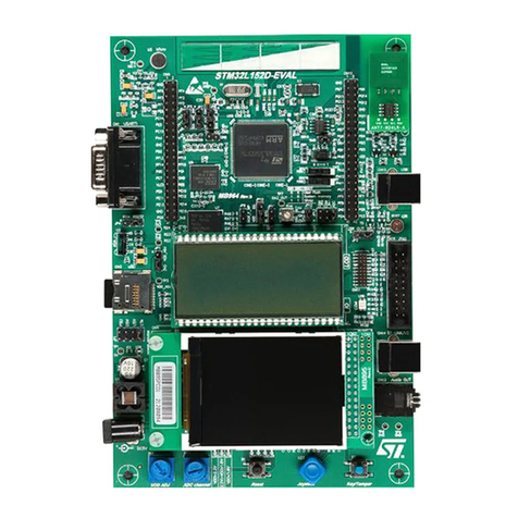
ST STM8/128-EVAL User manual

August 2008 Rev 2 1/41
41
UM0482
User manual
STM8/128-EVAL
evaluation board
Introduction
The STM8S2xx evaluation board STM8/128-
EVAL is designed as a complete development
platform for STMicroelectronic's STM8 core-
based STM8S2xx microcontroller with
CAN2.0A/B compliant interface, I2C, SPI, two
UART channels with smartcard, IrDA and LIN
support, internal 2 Kbyte data Flash and
128 Kbyte code Flash, SWIM debugging support.
The full range of hardware features on the board
is able to help you evaluate all peripherals
(including motor control, CAN, MicroSD card,
smartcard, UART, LIN, IrDA) and develop your
own applications. Extension headers make it
possible to easily connect a daughter board or
wrapping board for your specific application.
Features
■Two 5 V power supply options: power jack or
daughter board
■Audio play and record
■64 or 128 Mbyte MicroSD card
■Both A&B type smartcard support
■64 Kbit I2C EEPROM
■2 channels of RS-232 communication
■IrDA transceiver
■2 channels of LIN communication
■CAN2.0A/B compliant connection
■Inductor motor control connector
■SWIM and STice debug support
■122x32 dot-matrix serial interface LCD module
■Joystick with 4-direction control and selector
■Reset, Wakeup, Tamper and User button
■4 LEDs
■Extension connector for daughter board or
wrapping board.
Figure 1. STM8/128-EVAL evaluation board
www.st.com
Downloaded from Arrow.com.

Contents UM0482
2/41
Contents
1 Hardware layout and configuration . . . . . . . . . . . . . . . . . . . . . . . . . . . . . 4
1.1 Power supply . . . . . . . . . . . . . . . . . . . . . . . . . . . . . . . . . . . . . . . . . . . . . . . 7
1.2 Clock source . . . . . . . . . . . . . . . . . . . . . . . . . . . . . . . . . . . . . . . . . . . . . . . . 7
1.3 Reset source . . . . . . . . . . . . . . . . . . . . . . . . . . . . . . . . . . . . . . . . . . . . . . . 8
1.4 Audio . . . . . . . . . . . . . . . . . . . . . . . . . . . . . . . . . . . . . . . . . . . . . . . . . . . . . 8
1.5 I2C EEPROM . . . . . . . . . . . . . . . . . . . . . . . . . . . . . . . . . . . . . . . . . . . . . . . 9
1.6 CAN . . . . . . . . . . . . . . . . . . . . . . . . . . . . . . . . . . . . . . . . . . . . . . . . . . . . . . 9
1.7 RS-232 . . . . . . . . . . . . . . . . . . . . . . . . . . . . . . . . . . . . . . . . . . . . . . . . . . . . 9
1.8 LIN . . . . . . . . . . . . . . . . . . . . . . . . . . . . . . . . . . . . . . . . . . . . . . . . . . . . . . . 9
1.9 Motor control . . . . . . . . . . . . . . . . . . . . . . . . . . . . . . . . . . . . . . . . . . . . . . 10
1.10 Smartcard . . . . . . . . . . . . . . . . . . . . . . . . . . . . . . . . . . . . . . . . . . . . . . . . . 11
1.11 MicroSD card . . . . . . . . . . . . . . . . . . . . . . . . . . . . . . . . . . . . . . . . . . . . . . 11
1.12 Analog input . . . . . . . . . . . . . . . . . . . . . . . . . . . . . . . . . . . . . . . . . . . . . . . 11
1.13 IrDA . . . . . . . . . . . . . . . . . . . . . . . . . . . . . . . . . . . . . . . . . . . . . . . . . . . . . 12
1.14 Development and debug support . . . . . . . . . . . . . . . . . . . . . . . . . . . . . . . 12
1.15 Display and input devices . . . . . . . . . . . . . . . . . . . . . . . . . . . . . . . . . . . . . 12
2 Connectors . . . . . . . . . . . . . . . . . . . . . . . . . . . . . . . . . . . . . . . . . . . . . . . 13
2.1 STice connector CN2 . . . . . . . . . . . . . . . . . . . . . . . . . . . . . . . . . . . . . . . . 13
2.2 Analog input connector CN3 . . . . . . . . . . . . . . . . . . . . . . . . . . . . . . . . . . 14
2.3 SWIM connectors CN4 and CN17 . . . . . . . . . . . . . . . . . . . . . . . . . . . . . . 15
2.4 Power connector CN6 . . . . . . . . . . . . . . . . . . . . . . . . . . . . . . . . . . . . . . . 15
2.5 Audio jack CN7 . . . . . . . . . . . . . . . . . . . . . . . . . . . . . . . . . . . . . . . . . . . . . 15
2.6 CAN D-type 9-pin male connector CN8 . . . . . . . . . . . . . . . . . . . . . . . . . . 16
2.7 MicroSD connector CN9 . . . . . . . . . . . . . . . . . . . . . . . . . . . . . . . . . . . . . . 16
2.8 Motor control connector CN10 . . . . . . . . . . . . . . . . . . . . . . . . . . . . . . . . . 17
2.9 LIN connectors CN11 and CN14 . . . . . . . . . . . . . . . . . . . . . . . . . . . . . . . 18
2.10 Smartcard connector CN12 . . . . . . . . . . . . . . . . . . . . . . . . . . . . . . . . . . . 18
2.11 RS-232 connectors CN13 and CN15 . . . . . . . . . . . . . . . . . . . . . . . . . . . . 19
2.12 QST connector CN16 . . . . . . . . . . . . . . . . . . . . . . . . . . . . . . . . . . . . . . . . 19
2.13 Daughter board extension connectors CN1 and CN5 . . . . . . . . . . . . . . . 20
Downloaded from Arrow.com.
UM0482 Contents
3/41
3 Schematics . . . . . . . . . . . . . . . . . . . . . . . . . . . . . . . . . . . . . . . . . . . . . . . 24
Appendix A STM8/128-EVAL IO assignment . . . . . . . . . . . . . . . . . . . . . . . . . . . . 37
Revision history . . . . . . . . . . . . . . . . . . . . . . . . . . . . . . . . . . . . . . . . . . . . . . . . . . . . 40
Downloaded from Arrow.com.

Hardware layout and configuration UM0482
4/41
1 Hardware layout and configuration
The STM8/128-EVAL evaluation board is designed around the STM8S2xx microcontroller in
an 80-pin TQFP package. The hardware block diagram Figure 2 illustrates the connection
between STM8S2xx and peripherals (LCD, I2C EEPROM, UART, IrDA, LIN, Audio, CAN
bus, smartcard, MicroSD card and motor control) and Figure 3 will help you locate these
features on the actual evaluation board.
Figure 2. Hardware block diagram
ADC2
UART1
UART3
ADC2
Downloaded from Arrow.com.

UM0482 Hardware layout and configuration
5/41
Figure 3. STM8/128-EVAL evaluation board top layout
1. RV1 is connected to AIN9 instead of AIN8 as mentioned on the silkscreen.
2. CN13 and CN15 correspond to UART1 and UART3, instead of USART1 and USART2, as mentioned on the silkscreen.
CN5, CN1
Extension header
CN3
BNC connector
CN10
Motor control
U14
IrDA
U1
STM8S2xx
CN8
CAN
CN13
USART1(2)
CN15
USART2(2)
CN6
5V power
CN11
LIN1
connector
CN14
LIN2
connector
CN4
SWIM
U13
Dot-matrix
LCD
CN16
QST
connector
CN7
Audio jack
B2
KEY
U9
Joystick
B1
RESET
CN9
MicroSD card
U8
MIC
RV1
Potentiometer(1)
R75
resistor
Downloaded from Arrow.com.
UM0482 Hardware layout and configuration
7/41
1.1 Power supply
The STM8/128-EVAL evaluation board is designed to be powered by 5 V DC power supply
and to be protected by the PolyZen (auto rearmable fuse) U2 from wrong power plug-in
event. It is possible to configure the evaluation board to use any of following sources for the
power supply.
●5 V DC power adapter connected to CN6, the Power Jack on the board (PSU on silk
screen for power supply unit).
●5 V DC power from both CN5 and CN1, the extension connector for daughter board
(DTB for daughter board on silkscreen).
The power supply is configured by setting the related jumpers JP3 and JP2 as described in
Ta bl e 1 .
The LED LD5 is lit when the STM8/128-EVAL evaluation board is powered from the 5V
supply, and LD6 is also lit when the 3.3 V power regulator U3 is present.
1.2 Clock source
One clock source is available on the STM8/128-EVAL evaluation board for STM8S2xx:
●X1, 24 MHz crystal with socket for STM8S2xx microcontroller
It can be removed from the socket when the internal RC clock is used.
Table 1. Power related jumpers
Jumper Description
JP3
JP3 is used to select one of the two possible power supply resources.
For power supply jack(CN6) to the STM8/128-EVAL only, JP3 is set
as shown.
This is the default setting.
For power supply from the daughter board connectors (CN5 and
CN1) to STM8/128-EVAL only, JP3 is set as shown.
For power supply from power supply jack(CN6) to both
STM8/128-EVAL and daughter board connected on CN5 and CN1,
JP3 is set as shown (daughter board must have not its own
power supply connected).
JP2 Measures the consumption of both VDD and VDDA.
Default setting: Fitted
PSU
DTB
PSU
DTB
PSU
DTB
Downloaded from Arrow.com.
Hardware layout and configuration UM0482
8/41
1.3 Reset source
The reset signal of STM8/128-EVAL evaluation board is low active and the reset sources
include:
●Reset button B1
●Debugging Tools from connector CN4
●Daughter board from CN5
The reset pin PA0 of STM8S2XX is connected either to Reset button B1 or to GND by
setting the jumper JP1 as described in Ta b le 2 .
1.4 Audio
The STM8/128-EVAL evaluation board supports both audio recording and playback. This
can be disabled or enabled by setting the jumpers JP4 and JP5. Audio volume can be
adjusted using the potentiometer RV2, while the microphone amplifier gain can be adjusted
using potentiometer RV3.
The beeper function pin PD4 is connected to the speaker via the JP14 jumper which can be
used to select the source, beeper or PWM output from STM8S2xx.
Table 2. Reset related jumpers
Jumper Description
JP1
PA0 is connected to GND when JP1 is set as shown. It is used to
maintain the reset pin at low level while STice is connected to the
board.
PA0 is connected to Reset button when JP1 is set as shown.
This is the default setting.
1 2 3
1 2 3
Table 3. Audio related jumpers
Jumper Description
JP4
The audio power amplifier TS4871 is forced into standby mode when JP4 is not
fitted.
Default setting: fitted
JP5
The microphone pre-amplifier MAX4061 is forced into shutdown mode when JP5 is
fitted.
Default setting: not fitted
JP14
Either beeper or PWM output can be selected as a source of
speaker by setting the jumper JP14. The beeper is connected to
speaker when JP14 is set as shown opposite.
The PWM output is connected to speaker when JP14 is set as
shown opposite.
This is the default setting.
1 2 3
1 2 3
Downloaded from Arrow.com.
UM0482 Hardware layout and configuration
9/41
1.5 I2C EEPROM
A 64Kbit I2C EEPROM is connected to the I2C port of STM8S2xx. Write protection can be
enabled by setting jumper JP8.
1.6 CAN
The STM8/128-EVAL evaluation board supports CAN2.0A/B compliant CAN bus
communication based on 5 V CAN transceiver. The High-speed mode and low-speed mode
are available and can be selected by setting JP6.
1.7 RS-232
Two D-type 9-pin connectors CN13 (UART1) and CN15 (UART3) are available on the
STM8/128-EVAL evaluation board. The USART1 connector is connected to channel 3 of the
multiplexer U17, while the USART2 connector is connected to channel 1 of the multiplexer
U18.
Note: UART1 and UART3 are named USART1 and USART2 on the silkscreen (refer to Figure 3).
1.8 LIN
Two D-type 9-pin LIN connectors CN11 (LIN1) and CN14 (LIN2) are available on the
STM8/128-EVAL evaluation board. The LIN1 connector is connected to channel 4 of the
multiplexer U17, while the LIN2 connector is connected to channel 0 of the multiplexer U18.
Either master or slave operation mode is supported by both LIN connectors and can be
Table 4. I2C EEPROM related jumper
Jumper Description
JP8 I2C EEPROM U12 is protected from write operations when JP8 is not fitted.
Default setting: fitted
Table 5. CAN related jumpers
Jumper Description
JP6
CAN transceiver operates in low-speed mode when JP6 is set as
shown:
CAN transceiver operates in high-speed mode when JP6 is set as
shown:
This is the default setting.
JP7 CAN terminal resistor is enabled when JP7 is fitted.
Default setting: not fitted.
1 2 3
1 2 3
Downloaded from Arrow.com.

Hardware layout and configuration UM0482
10/41
selected by setting jumpers JP11 and JP12. The LIN1 and LIN2 transceivers are powered
by an external voltage from 6V to 26V connected to pin 9 of the LIN DB9 connector.
1.9 Motor control
The STM8/128-EVAL evaluation board supports inductor motor control via a 34-pin
connector CN10, which provides all required control and feedback signals to and from the
motor power-driving board. Available signals on this connector include emergency stop,
motor speed, 3-phase motor current, bus voltage, heatsink temperature coming from the
motor driving board and 6 channels of PWM control signals going to the motor driving
circuit.
Either PFC_PWM or Dissipative_Brake signal can be enabled by setting jumper JP13.
Table 6. LIN related jumpers
Jumper Description
JP11
LIN1 operates in master mode when JP11 is set as shown:
This is the default setting.
LIN1 operates in slave mode when JP11 is set as shown:
JP12
LIN2 operates in master mode when JP12 is set as shown:
LIN2 operates in slave mode when JP12 is set as shown:
This is the default setting.
1 2 3
1 2 3
1 2 3
1 2 3
Table 7. Motor control related configuration
Jumper/resis
tor Description
JP13
PFC_PWM signal is enabled and connected to PD0 when JP13 is
set as shown:
This is the default setting.
Dissipative_Brake signal is enabled and connected to PD0 when
JP13 is set as shown:
1 2 3
1 2 3
Downloaded from Arrow.com.
UM0482 Hardware layout and configuration
11/41
1.10 Smartcard
STMicroelectronics smartcard interface chip ST8024 is used on STM8/128-EVAL board for
asynchronous 3V and 5V smartcards. It performs all supply protection and control functions
based on the connections with STM8S2XX listed in Ta bl e 8 :
1.11 MicroSD card
The 64Mbyte (or 128MByte) MicroSD card SMS064FF (or SMS128FF) connected to the
SPI of STM8S2xx through a voltage level translator U11 (shared with LCD) is available on
the board. MicroSD card Chip Select is managed by standard IO port PE5 and the card
present is detected by port PE4.
1.12 Analog input
One BNC connector CN3 is connected to PF4, the ADC2 channel 12 of STM8S2xx as
external analog input.
JP9
JP9 should be kept open when encoder signal is from pin 31 of CN10 while it should
be kept closed when analog signal is from pin 31 of CN10 for special motor.
Default setting: not fitted
R75
This 47kΩmust be removed from the board to enable encoder phase A feature for
motor control applications. The location of this resistor is indicated in Figure 3 on
page 5.
Table 7. Motor control related configuration (continued)
Jumper/resis
tor Description
Table 8. Connection between ST8024 and STM8S2xx
Jumper Description
5V/3V Smartcard power supply selection pin. PG4
I/OUC MCU data I/O line
PA5 through
channel2 of
multiplexer U17
XTAL1 Crystal or external clock input PA6
OFF Detect presence of a card, Interrupt to MCU PE0
RSTIN Card Reset Input from MCU PG5
CMDVCC Start activation sequence input (Active Low) PG7
Downloaded from Arrow.com.
Hardware layout and configuration UM0482
12/41
1.13 IrDA
IrDA communication is supported by the IrDA transceiver U14 connected to the UART1 of
STM8S2xx through channel 1 of multiplexer U17. It can be enabled or disabled by setting
JP10:
1.14 Development and debug support
The debug connectors available on the STM8/128-EVAL evaluation board are:
●CN2, 120-pin SAMTEC connector that supports STice, the advanced emulation system
from STMicroelectronics. The JP1 jumper must connect pin 2 together with pin 3 when
STice is present, as described in Table 2: Reset related jumpers.
●CN4, ERNI 4-pin connector for SWIM debugging
●CN17, 2.54mm pitch low-cost 4-pin connector footprint for SWIM debugging (not
populated)
1.15 Display and input devices
The 122x32 Dot-matrix serial interface LCD (U13) and 4 general purpose LEDs (LD1, 2, 3,
4) are available as display devices. The LCD backlight can be switched ON or OFF by
setting IO PH4. A 4-direction joystick with selection key and general purpose button (B2) are
available as input devices.
Table 9. IrDA related jumpers
Jumper Description
JP10
JP10 is used to shut down the IrDA transceiver.
IrDA is enabled when JP10 is fitted, while IrDA is disabled when JP10 is not fitted.
Default status: fitted.
Table 10. LCD modules
122x32 Dot Matrix LCD U13
Pin on U13 Description Pin connection
1 Vss GND
2 Vcc +5V
3VO-
4CLKPC5
5SIDPC6
6CSPF0
7A+5V
8 K To GND through a transistor
Downloaded from Arrow.com.
UM0482 Connectors
13/41
2 Connectors
2.1 STice connector CN2
Figure 5. STice debugging connector CN2 (top view)
Table 11. STice debugging connector (CN2) pin description
Pin number Description Pin number Description
1 PA0 2 PA1
3PA2 4GND
5 GND 6 VCAP
75V 85V
9PA3 10PA4
11 PA5 12 PA6
13 PH0 14 PH1
15 PH2 16 PH3
17 PF7 18 PF6
19 PF5 20 PF4
21 PF3 22 PF2
23 5V VDDA 24 GND
25 PF1 26 PF0
27 PB7 28 PB6
29 PB5 30 PB4
31 PB3 32 PB2
33 PB1 34 PB0
35 PH4 36 PH5
37 PH6 38 PH7
39 PE7 40 PE6
41 PE5 42 PC0
43 PC1 44 PC2
45 PC3 46 PC4
47 PC5 48 GND
Downloaded from Arrow.com.
Connectors UM0482
14/41
2.2 Analog input connector CN3
Figure 6. Analog input connector CN3 (bottom view)
49 5V 50 PC6
51 PC7 52 PG0
53 PG1 54 PG2
55 PG3 56 PG4
57 PI0 58 NC
59 NC 60 NC
61 PI2 62 PI1
63 PI4 64 PI3
65 PG5 66 PI5
67 PG7 68 PG6
69 PE3 70 PE4
71 PE1 72 PE2
73 PI6 74 PE0
75 PD0 76 PI7
77 PD2 78 PD1
79 PD4 80 PD3
81 PD6 82 PD5
83 NC 84 PD7
85-120 NC
Table 11. STice debugging connector (CN2) pin description (continued)
Pin number Description Pin number Description
Table 12. Analog input connector CN3 pin description
Pin number Description Pin number Description
1 GND 4 GND
2 GND 5 Analog input/PF4
3GND
1
2
3
4
Downloaded from Arrow.com.

UM0482 Connectors
15/41
2.3 SWIM connectors CN4 and CN17
Figure 7. SWIM debugging connector CN4 (top view)
2.4 Power connector CN6
Your STM8/128-EVAL evaluation board can be powered from a DC 5V power supply via the
external power supply jack (CN6) shown in Figure 8. The central pin of CN6 must be
positive.
Figure 8. Power supply connector CN6 (front view)
2.5 Audio jack CN7
A 3.5mm Mono audio jack CN7 is available on the STM8/128-EVAL board. The speaker U5
is bypassed when an earphone is plugged into CN7.
Table 13. SWIM debugging connector CN4 and CN17 pin description
Pin number Description Pin number Description
1VDD 2PD1
3 GND 4 PA0 (RESET)
1 2 3 4
DC +5V
GND
Downloaded from Arrow.com.
Connectors UM0482
16/41
2.6 CAN D-type 9-pin male connector CN8
Figure 9. CAN D-type 9-pins male connector CN8 (front view)
2.7 MicroSD connector CN9
Figure 10. MicroSD connector CN9 (front view)
Table 14. CAN D-type 9-pins male connector CN8 pin description
Pin number Description Pin number Description
1,4,8,9 NC 7 CANH
2 CANL 3,5,6 GND
Table 15. MicroSD connector CN9 pin description
Pin number Description Pin number Description
1 Reserved 5 SCLK/PC5
2 CS/PE5 6 Vss/GND
3 DI/PC6 7 DO/PC7
4 VDD 8 Reserved
9 GND 10 PE4 to detect card present
Downloaded from Arrow.com.
UM0482 Connectors
17/41
2.8 Motor control connector CN10
Figure 11. Motor control connector CN10 (top view)
Table 16. Motor control connector CN10 pin description
Description Pin of
STM8S2xx
Pin number
of CN10
Pin number
of CN10
Pin of
STM8S2xx Description
EMERGENCY
STOP PE3 1 2 GND
PWM-UH PC1 3 4 GND
PWM-UL PH7 5 6 GND
PWM-VH PC2 7 8 GND
PWM-VL PH6 9 10 GND
PWM-WH PC3 11 12 GND
PWM-WL PH5 13 14 PB3 BUS VOLTAGE
PHASE A
CURRENT PB2 15 16 GND
PHASE B
CURRENT PB1 17 18 GND
PHASE C
CURRENT PB0 19 20 GND
NTC BYPASS
RELAY PG2 21 22 GND
D I S S I PAT I V E
BRAKE PWM
PD0 shared
with pin29 23 24 GND
+5V power 25 26 PE7 Heatsink
temperature
PFC SYNC PD2 27 28 3.3V power
PFC PWM PD0 shared
with pin23 29 30 GND
Encoder A PD3 31 32 GND
Encoder B PD4 33 34 PA3 Encoder Index
33 31 29 27 25 23 21 19 17 15 13 11 9 7 5 3 1
34 32 30 28 26 24 22 20 18 16 14 12 10 8 6 4 2
Downloaded from Arrow.com.

Connectors UM0482
18/41
2.9 LIN connectors CN11 and CN14
Figure 12. LIN connector CN11 (LIN1) and CN14 (LIN2) front view
2.10 Smartcard connector CN12
Figure 13. Smartcard connector CN12 (front view)
Table 17. LIN connector CN11 (LIN1) and CN14 (LIN2) pin connection
Pin number Description Pin number Description
1NC 6NC
2 NC 7 LIN wire
3GND 8NC
4 NC 9 Battery power input
5NC
Table 18. Smartcard connector CN12 pin description
Pin number Description Pin number Description
1VCC 5GND
2RST 6NC
3CLK 7I/O
4NC 8NC
9 Detection pin of card presence 10 Detection pin of card presence
1234
910
5678
Downloaded from Arrow.com.

UM0482 Connectors
19/41
2.11 RS-232 connectors CN13 and CN15
Figure 14. RS-232 connectors CN13 and CN15 (top view)
2.12 QST connector CN16
The QST connector is designed to be connected to the QST evaluation board powered by
DC 1.8V to 5V.
Figure 15. QST connector CN16 (front view)
Table 19. RS-232 connector CN13 and CN15 pin description
Pin number Description Pin number Description
1 NC 6 Connect to Pin 4
2 USART_RXD 7 Connect to Pin 8
3 USART_TXD 8 Connect to Pin 7
4 Connect to Pin 6 9 NC
5GND
Table 20. QST connector CN16 pin description
Pin number Description Pin number Description
1+5V 2+5V
3 PE1 4 PC5
5 PE2 6 PC6
7PA3 8PC7
9PI0 10PI1
11 PD3 12 QST_VDD
13 GND 14 GND
13 11 9 7 5 3 1
14 12 10 8 6 4 2
Downloaded from Arrow.com.

Connectors UM0482
20/41
2.13 Daughter board extension connectors CN1 and CN5
Two 50-pin male headers CN1 and CN5 can be used to connect a daughter board or
standard wrapping board to the STM8/128-EVAL evaluation board. All GPI/Os are available
on it. The space between the two connectors and the position of the power, GND and
RESET pins (marked in gray in Ta bl e 2 1 and Ta bl e 2 2 ) are defined as a standard which
allows to develop common daughter boards for several evaluations boards. The standard
width between CN1 pin1 and CN5 pin1 is 2700mils (68.58mm). This standard is
implemented on the majority of evaluation boards. Each pin on CN1 and CN5 can be used
by a daughter board after disconnecting it from the corresponding function block on the
STM8/128-EVAL evaluation board. Please refer to Ta b l e 21 and Ta bl e 2 2 for details.
Table 21. Daughter board extension connector CN1
Pin (1) Description Alternative function How to disconnect function block on STM8/128-EVAL board
1GND - -
3 PI6 Dip-Switch 6 Keep S2 OFF and remove R99.
5 PE1 I2C EEPROM Remove R95
7 PE3 MC connector pin1 Disconnect STM8/128-EVAL evaluation board from motor power
drive board, remove R60.
9 PG7 SmartCard_CMDVCC -
11 PG5 SmartCard_RST -
13 PI4 Dip-Switch 4 Keep S2 OFF and remove R58.
15 PI2 Dip-Switch 2 Keep S1 OFF and remove R9.
17 PI0 Dip-Switch 0 Keep S1 OFF and remove R7.
19 GND - -
21 PG2 MC connector pin21 Disconnect STM8/128-EVAL evaluation board from motor power
drive board
23 PG0 CAN_TX -
25 PC6 SPI MOSI Remove R34
27 PC4 PWM to speaker -
29 PC3 MC connector pin11 Disconnect STM8/128-EVAL evaluation board from motor power
drive board
31 NC - -
33 PC1 MC connector pin3 Disconnect STM8/128-EVAL evaluation board from motor power
drive board
35 PE5 SD card select Remove R34
37 PE7 MC connector pin26 Disconnect STM8/128-EVAL evaluation board from motor power
drive board, remove C33.
39 GND - -
41 PH5 MC connector pin13 Disconnect STM8/128-EVAL evaluation board from motor power
drive board
43 NC - -
Downloaded from Arrow.com.
Table of contents
Other ST Motherboard manuals

ST
ST AEK-POW-LDOV01J User manual

ST
ST STM8L101-EVAL User manual

ST
ST NUCLEO-WL55JC STM32WL User manual

ST
ST STR730-EVAL User manual

ST
ST EVAL-L9963-MCU Installation and operating instructions

ST
ST EVALSTGAP2S User manual

ST
ST STM8L15LPBOARD User manual

ST
ST SPC582B-DIS User manual

ST
ST STLINK-V3SEGT User manual

ST
ST STEVAL-IHM022V1 User manual