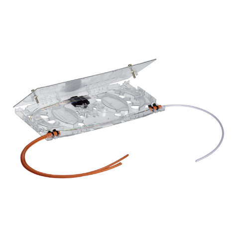
Stahl 8186 User manual

DE
EN
DE
EN
DE
EN
DE
EN
DE
EN
DE
EN
DE
EN
DE
EN
DE
Betriebsanleitung
Operating instructions
Additional languages www.stahl-ex.com
DE EN
Lichtwellenleiter-Spleißkassette
Optical Fibre Splice Cassette
8186


DE
DE
DE
DE
DE
DE
DE
DE
DE
DE
DE
DE
DE
DE
DE
DE
DE
DE
DE
DE
DE
DE
DE
DE
DE
Betriebsanleitung
Additional languages www.stahl-ex.com
DE
Lichtwellenleiter-Spleißkassette
8186

Allgemeine Angaben
2203681 / 818660300010
2016-03-24·BA00·III·de·03
Lichtwellenleiter-Spleißkassette
8186
DE
DE
DE
DE
DE
DE
DE
DE
DE
DE
DE
DE
DE
DE
DE
DE
DE
DE
DE
DE
DE
DE
DE
DE
DE
Inhaltsverzeichnis
1 Allgemeine Angaben ...........................................................................................2
1.1 Hersteller .............................................................................................................2
1.2 Angaben zur Betriebsanleitung ...........................................................................2
2 Verwendete Symbole ..........................................................................................3
3 Verwendung ........................................................................................................3
4 Allgemeine Sicherheitshinweise .........................................................................3
5 Normenkonformität .............................................................................................3
6 Technische Daten ...............................................................................................4
7 Transport und Lagerung .....................................................................................4
8 Maßangaben .......................................................................................................5
9 Übersicht Lichtwellenleiter-Spleißkassette .........................................................5
10 Montage und Demontage ...................................................................................5
11 Installation ...........................................................................................................6
11.1 Mögliche Verlegearten ........................................................................................6
11.2 Lichtwellenleiter anschließen ..............................................................................7
12 Befestigung .........................................................................................................8
13 Inbetriebnahme ...................................................................................................8
14 Instandhaltung, Wartung und Störbeseitigung ....................................................9
15 Entsorgung ..........................................................................................................9
16 Zubehör und Ersatzteile ......................................................................................9
1 Allgemeine Angaben
1.1 Hersteller
R. STAHL Schaltgeräte GmbH
Am Bahnhof 30
74638 Waldenburg
Germany
Tel.: +49 7942 943-0
Fax: +49 7942 943-4333
Internet: www.stahl-ex.com
E-Mail: [email protected]
1.2 Angaben zur Betriebsanleitung
ID-Nr. 203681 / 818660300010
Publikationsnummer: 2016-03-24·BA00·III·de·03
Änderungen vorbehalten.
203681 / 818660300010
2016-03-24·BA00·III·de·03
Verwendete Symbole
3
Lichtwellenleiter-Spleißkassette
8186
DE
DE
DE
DE
DE
DE
DE
DE
DE
DE
DE
DE
DE
DE
DE
DE
DE
DE
DE
DE
DE
DE
DE
DE
DE
2 Verwendete Symbole
3 Verwendung
Die Lichtwellenleiter- (LWL) Spleißkassette ist eine explosionsgeschützte Komponente
zum Verbinden von Lichtwellenleitern in explosionsgeschützten Bereichen.
Für den Einsatz in gas- oder staubexplosionsgefährdeten Bereichen muss
die LWL-Spleißkassette in ein geeignetes Schutzgehäuse eingebaut werden.
4 Allgemeine Sicherheitshinweise
Die Geräte sind nur für den zugelassenen Einsatzzweck zu verwenden. Fehlerhafter
oder unzulässiger Einsatz sowie das Nichtbeachten der Hinweise dieser Betriebsan-
leitung schließen eine Gewährleistung unsererseits aus. Umbauten und Veränderungen
am Gerät, die den Explosionsschutz beeinträchtigen, sind nicht gestattet. Das Gerät darf
nur im unbeschädigten und sauberen Zustand betrieben werden.
Bei Installation und Betrieb ist Folgendes zu beachten:
- Beschädigungen können den Explosionsschutz aufheben
- Nationale und örtliche Sicherheitsvorschriften
- Nationale und örtliche Unfallverhütungsvorschriften
- Nationale und örtliche Montage- und Errichtungsvorschriften (z.B. IEC/EN 60079-14)
- Allgemein anerkannte Regeln der Technik
- Sicherheitshinweise dieser Betriebsanleitung
- Kennwerte und Bemessungsbetriebsbedingungen der Typ- und Datenschilder
- Zusätzliche Hinweisschilder auf dem Gerät
5 Normenkonformität
Die relevanten Normen sind in der EG-Konformitätserklärung bzw. dem
IECEx Certificate of Conformity aufgelistet.
Diese Dokumente können im Download-Bereich der Internetseite www.stahl-ex.com
abgerufen werden.
Symbol Bedeutung
05594E00
CE-Kennzeichnung gemäß aktuell gültiger Richtlinie.
02198E00
Gerät gemäß Kennzeichnung für explosionsgefährdete Bereiche zertifiziert.
WARNUNG
Installation, Instandhaltung, Wartung und Störbeseitigung darf nur von dazu befugtem
und entsprechend geschultem Personal durchgeführt werden.

Technische Daten
4203681 / 818660300010
2016-03-24·BA00·III·de·03
Lichtwellenleiter-Spleißkassette
8186
DE
DE
DE
DE
DE
DE
DE
DE
DE
DE
DE
DE
DE
DE
DE
DE
DE
DE
DE
DE
DE
DE
DE
DE
DE
6 Technische Daten
7 Transport und Lagerung
- Transport und Lagerung sind nur in Originalverpackung gestattet.
Technische Daten
Explosionsschutz
Global (IECEx)
Gas IECEx PTB 10.0060 U
Ex op pr IIC Gb
Europa (ATEX)
Gas PTB 10 ATEX 2015 U
E II 2 G Ex op pr IIC Gb
Bescheinigungen und
Zertifikate
Bescheinigungen IECEx, ATEX, Brasilien (INMETRO), Indien (PESO),
Kasachstan (TR), Korea (KCs), Russland (TR), Serbien (SRPS),
Taiwan (ITRI), Weißrussland (TR)
Elektrische Daten
Grenzwerte
Nennleistung bis 100 mW
Frequenz 10 MHz, 100 MHz, 1 GHz, 10 GHz
Umgebungs-
bedingungen
Umgebungs-
temperatur
-40 ... +60 °C
Mechanische Daten
Kabeldurchmesser 6,5 mm
max. Durchmesser
für Spleißschutz-
halter
3 mm
Mindestbiegeradius 35 mm
Gehäusematerial Polycarbonat, flammwidrig, halogenfrei, UL94 V-0
Max. Anzahl LWL 6 mit 1 Spleißschutzhalter, 12 mit 2 Spleißschutzhaltern
Zubehör-Set (Art.Nr. 203682), bitte separat bestellen:
1 x Spleißschutzhalter 6-fach, 6 x Schrumpfspleißschutz,
4 x Kabelbinder
Abmessungen 210 x 104 x 10 mm (L x B x H)

203681 / 818660300010
2016-03-24·BA00·III·de·03
Maßangaben
5
Lichtwellenleiter-Spleißkassette
8186
DE
DE
DE
DE
DE
DE
DE
DE
DE
DE
DE
DE
DE
DE
DE
DE
DE
DE
DE
DE
DE
DE
DE
DE
DE
8 Maßangaben
9 Übersicht Lichtwellenleiter-Spleißkassette
10 Montage und Demontage
Die Lichtwellenleiter dürfen nur mit den zugehörigen Spleißschutzhaltern mit
Schrumpfspleißschutz montiert werden.
Maßzeichnungen (alle Maße in mm [Zoll]) - Änderungen vorbehalten
14347E00
Übersicht Lichtwellenleiter-Spleißkassette
14215E00
1 = Deckel
2 = Spleißkassette
3 = Spleißschutzhalter 6-fach
Zubehör-Set (Art.Nr. 203682):
1 x Spleißschutzhalter, 6 x Schrumpfspleißschutz, 4 x Kabelbinder
175 [6,89]
42 [1,65]
ØØ
3 [ 0,12]
210 [8,27]
10
[0,39]
ØØ
3,50 [ 0,14]
104 [4,09]
ØØ
6 [ 0,24]

Installation
6203681 / 818660300010
2016-03-24·BA00·III·de·03
Lichtwellenleiter-Spleißkassette
8186
DE
DE
DE
DE
DE
DE
DE
DE
DE
DE
DE
DE
DE
DE
DE
DE
DE
DE
DE
DE
DE
DE
DE
DE
DE
11 Installation
Vor dem Anschluss
- Alle Strahlungsquellen ausschalten und gegen unbefugtes Wiedereinschalten si-
chern.
- Sicherstellen, dass die Spleißkassette unversehrt und sauber ist.
- Sicherstellen, dass der angegebenen Mindestbiegeradius (35 mm) eingehalten wird.
11.1 Mögliche Verlegearten
Innerhalb der Spleißkassette können die Lichtwellenleiter wie folgt verlegt werden:
WARNUNG
Bei nicht korrekt installierten Komponenten ist der Explosionsschutz nicht mehr
gewährleistet.
Für den Einsatz in gasexplosionsgefährdeten Bereichen muss das Gerät in ein dafür
geeignetes, entsprechend bescheinigtes Schutzgehäuse eingebaut werden, das die
Mindestschutzart IP54 gemäß IEC/EN 60529 erfüllt.
Bei Einsatz in staubexplosionsgefährdeten Bereichen muss das Gerät in ein dafür
geeignetes, entsprechend bescheinigtes Schutzgehäuse eingebaut werden, das die
Mindestschutzart IP65 gemäß IEC/EN 60529 erfüllt.
Die Lichtwellenleiter müssen außerhalb des Schutzgehäuses so verlegt werden,
dass ein Schutz vor mechanischer Beschädigung gewährleistet ist.
Es ist darauf zu achten, dass im Schutzgehäuse nur Kabelverschraubungen
verwendet werden, die dafür geeignet sind und über eine entsprechende
Bescheinigung verfügen.
Außerhalb der LWL-Spleißkassette sind die Mindestbiegeradien
der Kabelhersteller zu beachten.
14060E00 14061E00
Variante 1 Variante 2

203681 / 818660300010
2016-03-24·BA00·III·de·03
Installation
7
Lichtwellenleiter-Spleißkassette
8186
DE
DE
DE
DE
DE
DE
DE
DE
DE
DE
DE
DE
DE
DE
DE
DE
DE
DE
DE
DE
DE
DE
DE
DE
DE
11.2 Lichtwellenleiter anschließen
- Spleißkassette öffnen: Muttern lösen und Deckel abheben.
14214E00
- Kabelummantelung und Bündeladern mit geeignetem Werkzeug gemäß Skizze
abisolieren. 1 = Kabelummantelung, 2 = Bündeladern, 3 = LWL-Fasern
14345E00
- Bündeladern mit Isolierband umwickeln und mit Kabelbindern an der unteren
Spleißkassetten-Gehäuseseite befestigen.
14062E00 14063E00
Variante 3 Variante 4
50
mm
1500
mm
1 2 3

Befestigung
8203681 / 818660300010
2016-03-24·BA00·III·de·03
Lichtwellenleiter-Spleißkassette
8186
DE
DE
DE
DE
DE
DE
DE
DE
DE
DE
DE
DE
DE
DE
DE
DE
DE
DE
DE
DE
DE
DE
DE
DE
DE
03569E00
- LWL-Fasern gemäß den Angaben des Spleißgeräteherstellers verspleißen.
- LWL, wie im Abschnitt „Mögliche Verlegearten“ dargestellt, innerhalb der
Spleißkassette verlegen.
- Schrumpfspleißschutz in den Spleißschutzhalter einklipsen.
- Vorgang für alle LWL-Fasern wiederholen.
- Spleißkassette schließen und mit Muttern sichern.
12 Befestigung
1 - Ø 6,0 mm: Befestigung mit Schraube M5
2 - Ø 2,9 mm: Befestigung mit Senkschraube M3
3 - Ø 3,5 mm: Befestigung mit Bolzen und Mutter M3
13 Inbetriebnahme
Vor Inbetriebnahme
- Sicherstellen, dass das Gerät nicht beschädigt ist.
- Sicherstellen, dass das Gerät vorschriftsmäßig installiert ist.
- Fremdkörper aus dem Gerät entfernen.
- Sicherstellen, dass Lichtwellenleiter und Kabelbinder fest in der Spleißkassette
arretiert sind.

203681 / 818660300010
2016-03-24·BA00·III·de·03
Instandhaltung, Wartung und Störbeseitigung
9
Lichtwellenleiter-Spleißkassette
8186
DE
DE
DE
DE
DE
DE
DE
DE
DE
DE
DE
DE
DE
DE
DE
DE
DE
DE
DE
DE
DE
DE
DE
DE
DE
14 Instandhaltung, Wartung und Störbeseitigung
Bei der Wartung sind folgende Punkte zu überprüfen:
- Fester Sitz der Leitungen
- Einhaltung der zulässigen Temperaturen (gemäß IEC/EN 60079)
- Beschädigungen am Gehäuse
Reparaturarbeiten
15 Entsorgung
Die nationalen Vorschriften zur Abfallbeseitigung sind zu beachten.
16 Zubehör und Ersatzteile
WARNUNG
Ist die Spleißkassette beschädigt, muss diese ausgetauscht werden. Eine Reparatur ist
nicht zulässig.
WARNUNG
Es sind nur Original-Zubehörteile und Original-Ersatzteile der Fa. R. STAHL zu
verwenden.
Zubehör und Ersatzteile
Benennung Abbildung Beschreibung Art. Nr. Gewicht
kg
Zubehör-Set,
Spleißschutz-
halter 6-fach 14350E00
für max. 6 LWL:
1 x Spleißschutzhalter 6-fach, 6 x
Schrumpfspleißschutz, 2 x Kabelbinder
203682 0,006

EN
EN
EN
EN
EN
EN
EN
EN
EN
EN
EN
EN
EN
EN
EN
EN
EN
EN
EN
EN
EN
EN
EN
EN
EN
Operating instructions
Additional languages www.stahl-ex.com
EN
Optical Fibre Splice Cassette
8186

General Information
2203681 / 818660300010
2016-03-24·BA00·III·en·03
Optical Fibre Splice Cassette
8186
EN
EN
EN
EN
EN
EN
EN
EN
EN
EN
EN
EN
EN
EN
EN
EN
EN
EN
EN
EN
EN
EN
EN
EN
EN
Contents
1 General Information ............................................................................................2
1.1 Manufacturer .......................................................................................................2
1.2 Information regarding the operating instructions .................................................2
2 Symbols Used .....................................................................................................3
3 Intended Use .......................................................................................................3
4 General Safety Notes ..........................................................................................3
5 Conformity to Standards .....................................................................................3
6 Technical data .....................................................................................................4
7 Transport and storage .........................................................................................4
8 Dimensions .........................................................................................................5
9 Overview Optical Fibre Splice Cassette ..............................................................5
10 Assembling and Dismantling ...............................................................................5
11 Installation ...........................................................................................................6
11.1 Possible Installation Methods .............................................................................6
11.2 Connecting the Optical Fibre Cables ..................................................................7
12 Fastening ............................................................................................................8
13 Putting into Service .............................................................................................8
14 Maintenance, overhaul and repair ......................................................................9
15 Disposal ..............................................................................................................9
16 Accessories and Spare Parts ..............................................................................9
1 General Information
1.1 Manufacturer
R. STAHL Schaltgeräte GmbH
Am Bahnhof 30
74638 Waldenburg
Germany
Tel.: +49 7942 943-0
Fax: +49 7942 943-4333
Internet: www.stahl-ex.com
E-Mail: [email protected]
1.2 Information regarding the operating instructions
ID-No.: 203681 / 818660300010
Publication Code: 2016-03-24·BA00·III·en·03
Subject to alterations.

203681 / 818660300010
2016-03-24·BA00·III·en·03
Symbols Used
3
Optical Fibre Splice Cassette
8186
EN
EN
EN
EN
EN
EN
EN
EN
EN
EN
EN
EN
EN
EN
EN
EN
EN
EN
EN
EN
EN
EN
EN
EN
EN
2 Symbols Used
3 Intended Use
The optical fibre (FO) splice cassette is an explosion-protected component for connection
of optical fibre cables in explosion-protected areas.
For use in areas with gas or dust explosion hazard the FO splice cassette must be
installed in a suitable protective enclosure.
4 General Safety Notes
The devices must be used only for the permitted purpose. Incorrect or impermissible use
or non-compliance with these instructions invalidates our warranty provision.
Any alterations and modifications to the device, impairing its explosion protection, are not
permitted. Use the device only if it is undamaged and clean.
Observe the following information during installation and operation:
- Any damage can invalidate the explosion protection
- National and local safety regulations
- National and local accident prevention regulations
- National and local assembly and installation regulations (e.g. IEC/EN 60079-14)
- Generally recognized technical regulations
- Safety instructions in these operating instructions
- Characteristic values and rated operating conditions on the rating and data plates
- Additional instruction plates fixed directly to the device
5 Conformity to Standards
The relevant standards are listed in the EC Declaration of Conformity or IECEx Certificate
of Conformity.
These documents can be downloaded in the download area on the internet page
www.stahl-ex.com.
Symbol Meaning
05594E00
CE marking according to the currently applicable directive.
02198E00
According to marking, device approved for hazardous areas.
WARNING
Installation, maintenance, overhaul and repair may only be carried out by appropriately
authorized and trained personnel.

Technical data
4203681 / 818660300010
2016-03-24·BA00·III·en·03
Optical Fibre Splice Cassette
8186
EN
EN
EN
EN
EN
EN
EN
EN
EN
EN
EN
EN
EN
EN
EN
EN
EN
EN
EN
EN
EN
EN
EN
EN
EN
6 Technical data
7 Transport and storage
- Transport and storage are only permitted in the original packaging.
Technical Data
Explosion
protection
Global (IECEx)
Gas IECEx PTB 10.0060 U
Ex op pr IIC Gb
Europe (ATEX)
Gas PTB 10 ATEX 2015 U
E II 2 G Ex op pr IIC Gb
Certifications and certif-
icates
Certificates IECEx, ATEX, Brazil (INMETRO), India (PESO),
Kazakhstan (TR), Korea (KCs), Russia (TR), Serbia (SRPS),
Taiwan (ITRI), Belarus (TR)
Electrical data
Limiting values
Rated power up to 100 mW
Frequency 10 MHz, 100 MHz, 1 GHz, 10 GHz
Ambient conditions
Ambient
temperature
-40 ... +60 °C
Mechanical data
Cable diameter 6,5 mm
max. diameter for
splice protection
holder
3 mm
Minimum bend
radius
35 mm
Enclosure material Polycarbonate, flame retardant, halogen-free, UL94 V-0
Max. number of FO 6 with 1 splice protector holder, 12 with 2 splice protector holders
accessories set (art. no. 203682), please order separately:
1 splice protector holder 6-way, 6 shrink splice protectors, 4 cable ties
Dimensions 210 x 104 x 10 mm (L x W x H)

203681 / 818660300010
2016-03-24·BA00·III·en·03
Dimensions
5
Optical Fibre Splice Cassette
8186
EN
EN
EN
EN
EN
EN
EN
EN
EN
EN
EN
EN
EN
EN
EN
EN
EN
EN
EN
EN
EN
EN
EN
EN
EN
8 Dimensions
9 Overview Optical Fibre Splice Cassette
10 Assembling and Dismantling
The fibre optics may only be mounted with the corresponding splice holders with shrink
splice protector.
Dimensional Drawings (All Dimensions in mm [inches]) - Subject to Alterations
14347E00
Overview Optical Fibre Splice Cassette
14215E00
1 = lid
2 = splice cassette
3 = splice protector holder 6-way
Accessories set (art. no. 203682):
1 splice holder, 6 shrink splice protectors, 4 cable ties
175 [6,89]
42 [1,65]
ØØ
3 [ 0,12]
210 [8,27]
10
[0,39]
ØØ
3,50 [ 0,14]
104 [4,09]
ØØ
6 [ 0,24]

Installation
6203681 / 818660300010
2016-03-24·BA00·III·en·03
Optical Fibre Splice Cassette
8186
EN
EN
EN
EN
EN
EN
EN
EN
EN
EN
EN
EN
EN
EN
EN
EN
EN
EN
EN
EN
EN
EN
EN
EN
EN
11 Installation
Before connection
- Switch off all sources of radiation and secure them against being switched on again
without authorisation.
- Make sure that the splice cassette is intact and clean.
- Make sure that the specified minimum bending radius (35 mm) is observed.
11.1 Possible Installation Methods
Inside the splice cassette, the optical fibre cables can be installed as follows:
WARNING
If the components are installed incorrectly, explosion protection is no longer
guaranteed.
For use in areas with explosive gas atmosphere the device must be installed into a
suitable protective enclosure which is certified appropriately and fulfills the minimum
degree of protection IP54 according to IEC/EN 60529.
For use in areas with explosive dust atmosphere, the device must be installed in a
suitable protective enclosure certified which is certified appropriately and fulfills the
minimum degree of protection IP65 acc. to IEC/EN 60529.
The optical fibre cables must be installed outside the protective enclosure such that
protection from mechanical damage is guaranteed.
Make sure that only suitable cable glands with a corresponding certificate are used in
the protective enclosure.
Outside of the FO splice cassette the minimum bending radii of the cable
manufacturer are to be observed.
14060E00 14061E00
Version 1 Version 2

203681 / 818660300010
2016-03-24·BA00·III·en·03
Installation
7
Optical Fibre Splice Cassette
8186
EN
EN
EN
EN
EN
EN
EN
EN
EN
EN
EN
EN
EN
EN
EN
EN
EN
EN
EN
EN
EN
EN
EN
EN
EN
11.2 Connecting the Optical Fibre Cables
- Open splice cassette: loosen nuts and remove lid.
14214E00
- Remove the cable insulation and multifibre loose buffers using a suitable tool
according to the drawing. 1 = cable insulation, 2 = multifibre loose buffers,
3 = optical fibres
14345E00
- Wrap an insulating tape around the multifibre loose buffers and fasten them using
cable ties at the lower enclosure side of the splice cassette.
14062E00 14063E00
Version 3 Version 4
50
mm
1500
mm
1 2 3

Fastening
8203681 / 818660300010
2016-03-24·BA00·III·en·03
Optical Fibre Splice Cassette
8186
EN
EN
EN
EN
EN
EN
EN
EN
EN
EN
EN
EN
EN
EN
EN
EN
EN
EN
EN
EN
EN
EN
EN
EN
EN
03569E00
- Splice optical fibres according to the specifications of the manufacturer of the splicing
device.
- Lay the fibre optics inside of the splice cassette as described in section "Possible
installation methods".
- Snap shrink splice protector into the splice holder.
- Repeat the process for all optical fibres.
- Close the splice cassette and secure by means of nuts.
12 Fastening
1 - Ø 6.0 mm: Fastening with M5 screw
2 - Ø 2.9 mm: Fastening with M3 countersunk head screw
3 - Ø 3.5 mm: Fastening with M3 screw and nut
13 Putting into Service
Before putting into service
- Make sure that the device is not damaged.
- Make sure that the device is installed correctly.
- Remove any foreign objects from the device.
- Make sure that the optical fibre cable and the cable tie are firmly arrested in the splice
cassette.

203681 / 818660300010
2016-03-24·BA00·III·en·03
Maintenance, overhaul and repair
9
Optical Fibre Splice Cassette
8186
EN
EN
EN
EN
EN
EN
EN
EN
EN
EN
EN
EN
EN
EN
EN
EN
EN
EN
EN
EN
EN
EN
EN
EN
EN
14 Maintenance, overhaul and repair
The following details must be checked during maintenance:
- Cables are held securely in place
- Compliance with the permitted temperatures (acc. to IEC/EN 60079)
- Damage to the enclosure
Repair work
15 Disposal
The national waste disposal regulations have to be observed.
16 Accessories and Spare Parts
WARNING
In case the splice cassette is damaged, it must be replaced. Repair work is not permitted.
WARNING
Use only original R. STAHL accessories and spare parts.
Accessories and Spare Parts
Designation Figure Description Art. no. Weight
kg
Accessories set,
splice protector
holder 6-way
14350E00
for max. 6 FO:
1 splice protector holder 6-way, 6 shrink splice
protectors, 2 cable ties
203682 0.006
Other manuals for 8186
2
Table of contents
Languages:
Other Stahl Cables And Connectors manuals

Stahl
Stahl 9176 Rev C User manual

Stahl
Stahl 8570/12 User manual

Stahl
Stahl SolConeX 7570/12 Series User manual

Stahl
Stahl 8186 User manual

Stahl
Stahl 8169/1 Series User manual

Stahl
Stahl SolConeX 8573/12 Series User manual

Stahl
Stahl 9411/11 Series User manual

Stahl
Stahl 8595/1 Series User manual

Stahl
Stahl SolConeX 8581/41 User manual

Stahl
Stahl 9411/24 Series User manual