INSTALLATION OPERATION &
MAINTENANCE DATA SHEET
85 796 07 30 0 2 December 14, 2004
R. STAHL, INC.
9001 Knight Road
Houston, TX 77054
Tel: 800-782-4357 FAX: 713-792-9301
Website: www.rstahl.com
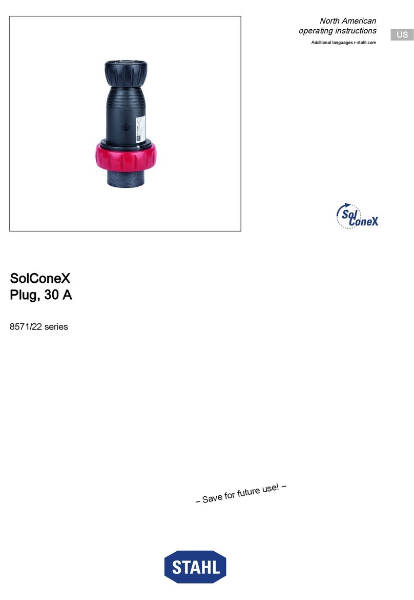
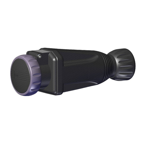
4. Wiring of Plug 8579/22
4.1. Cord Type
Select a flexible cord with copper conductors of the
appropriate insulation, ampacity and 90°C tempera-
ture rating. For installations in the U.S., refer to the
National Electrical Code, Articles 400-4, 400-5A, 400-
5B, 501-11, 502-12 and 503-10. For installation in
Canada refer to CEC section 4 & 18
NOTE: Maximum range for plug terminals is 10-6
AWG. Tighten terminal screws to 26.5 in-lbs
(3 N-m) torque.
4.2. Cord Preparation
Cut the cord cleanly - Do not strip away cord jacket or
conductor insulation at this time.
4.3. Opening the Plug
Referring to Figure 1 above, loosen screws ➀and pull
the plug body ➁out of the shell ➂.Loosen the screw
➃on the locking clamp ➄,insert the screwdriver in
the locking clamp slot, lift the locking clamp out of the
pressure ring ➅and unscrew the pressure ring.
4.4. Insert the Cord
Slide the pressure ring ➅and the washer ➆over
the cord.
4.4.1 Install Cord Grommet
The grommet ➇is a universal onion ring style which
accommodates several cord diameters by removing
(cutting out) the inner undersized diameters. The
grommet should fit snugly on the cord. The grommet
may require lubrication in order to slide over the cord.
Use talcum powder or an equivalent material rated for
use on electrical products. Slide the grommet over the
cord with the cuts toward the shell ➂.
NOTE: If the grommet slides freely over the cord,
there will be insufficient sealing for Class II
and Class III Hazardous Locations.
4.4.2 Slide the shell ➂over the cord.
4.5. Cord Preparation
Dress the cord by removing the outer jacket and fillers
for a length of 3-1/8" (80 mm) and strip the insulation
off of the conductors 5/8" (17 mm) from the end.
4.6. Connection to Terminals
Open the strain relief clamp screws ⑩and flip the
clamp to the side. Attach the leads to the appropriate
terminals 1
1.Terminal markings correspond to recep-
tacle terminal markings.
CAUTION: The Equipment Ground (green wire) is
to be connected to the terminal marked with the Earth
Ground symbol .
4.7. Strain Relief
Adjust the strain relief clamp ⑩to slide over the cord,
if necessary remove the clamp plastic inserts to fit the
plug body ➁.Then tighten the strain relief clamp ⑩.
4.8. Plug Assembly
4.8.1 Insert the plug body ➁into the shell ➂.To align the
plug body ➁with the shell ➂,the keyway on the
inside of the shell must mate with the rib in the plug
body.
4.8.2 Tighten the screws ➀.
4.8.3 Slide the grommet ➇and the gland washer ➆forward
until they shoulder against the shell ➂and tighten the
pressure ring ➅until a good grommet compression is
achieved.
4.8.4 Reinstall the locking clamp ➄and tighten the screw ➃.
4.9. The optional dust cap (P/N 85 798 01 14 0) must be
used for Class II, Divisions 1 & 2, Groups E or F
Hazardous Locations.
WARNING: Users shall observe the labels on the
plug and receptacle with regard to the use of recepta-
cle covers and dust caps.
5. Maintenance
These plugs and receptacles require no maintenance
other than a periodic inspection for damage and prop-
er operation. The surface of the plug pins should be
given a thorough inspection. Any damaged equipment
should be replaced promptly to ensure the electrical
safety and explosion protection of the system.
1
23
4
5
6
7
8
9
103/8
1 5/8
11
keyway
cord
Figure 1.
Note: The nature of these instructions is only informative and does not
cover all of the details, variations or combinations in which this
equipment may be used, its storage, delivery, installation, safe
operation and maintenance.Since conditions of use of the product
are outside of the care, custody and control of the manufacturer,
the purchaser should determine the suitability of the product for
his intended use, and assumes all risk and liability whatsoever in
connection therewith.
