Stahlwille Standard Manoskop 720 Nf/80 Parts list manual

25
STAHLWILLE
Torque Wrenches
Standard Manoskop®
720 Nf/80
721 Nf/80
721 Nf/100
Service Manoskop®
730/80
Technical
description
All models
Manoskop®720 Nf/80, 721 Nf/80,
721 Nf/100 and 730/80 are adjustable
torque wrenches with a cut-out, tactile
and audible cut-out signals.
•These torque wrenches have a
safety cut-out mechanism.
•The wrench is set to cut-out at a
certain torque level by setting the
required value on the N m/ft.lb scale
using a force-free knob.
•The setting knob has an automatic
setting fail-safe mechanism.
Content
Technical description . . . . . . . . . . . 25
Technical specifications . . . . . . . . . 27
ãImportant safety instructions . . . 28
Operation . . . . . . . . . . . . . . . . . . . . 30
Maintenance. . . . . . . . . . . . . . . . . . 39
Cleaning the Manoskop®........43
Accessories . . . . . . . . . . . . . . . . . . 44
Disposal . . . . . . . . . . . . . . . . . . . . . 44

26
•The measuring element is a flexible
rod. The flexible rod is not
pretensioned so it is only under
tension from the start to the end of
the actual tightening operation until
the wrench cuts out.
•As soon as the torque wrench is
released, it is ready for the next job.
•These wrenches will only tighten in
one direction. To use the Manoskop®
wrench for loosening, turn it over.
•If necessary, these torque wrenches
can be readjusted without
dismantling.
Maximum permissible deviation of the
set value from the absolute value at cut-
out is ± 4 %.
Manoskop®720 Nf/80, 721 Nf/80,
721 Nf/100 and 730/80 comply with
DIN EN ISO 6789, Type II, Class A.
Every Manoskop®has a unique serial
number and is supplied with a works
calibration certificate.
STAHLWILLE Standard
Manoskop®720 Nf/80 ...
... has a permanent, fixed head with an
exchangeable 20 (3/4'') square drive.
STAHLWILLE Standard
Manoskop®721 Nf/80 ...
... has a permanent, non-switchable
ratchet with an exchangeable 20 (3/4'')
square drive.
STAHLWILLE Standard
Manoskop®721 Nf/100 ...
... has a permanent, non-switchable
ratchet with an exchangeable 20 (3/4'')
square drive.

27
The wrench consists of a basic wrench
and a grip tube. The grip tube is placed
over the end of the basic wrench where it
locks in place by means of a locking pin
that locates in a hole. The locking pin is
attached to the grip tube by a spring-
loaded ring. To attach or remove the grip
tube (e.g. for setting), press the ring
against the wall of the tube which will
extract the locking pin. The locking
position is marked with an arrow.
STAHLWILLE Service
Manoskop®730/80 ...
... can be fitted with various shell tools.
For this purpose, the head of the wrench
has an external 24.5x28 square drive
pointing forwards with a spring-loaded
locking pin on the underside. The shell
tools can be attached in the „normal“
position or rotated through 180°.
Technical
specifications
alength to centre of square drive
bwith grip tube attached
Manoskop®720 and 721
720 Nf/80 721 Nf/80 721 Nf/100
Torque range [N m]
[ft.lb]
160–800
120–600
160–800
120–600
200–1000
150–725
Exchangeable square
drive [mm]
fixed
20 (3/4'')
ratchet
20 (3/4'')
ratchet
20 (3/4'')
Length Åa [mm] 1.013 1.013 1.466
b
Weight [g] 6.135 6.770 7.570
b
Manoskop®730
Torque range
shell square
drive
[mm]
Length Weight
Model
[N m] [ft.lb] [mm] [g]
730/80 160–800 120–600 24,5 x 28 970 4.960
28
Intended Purpose
Manoskop®720 Nf/80, 721 Nf/80,
721 Nf/100 und 730/80 have been
designed for controlled tightening of
screw joints. They may only be used for
this purpose. To do so, the correct
attachments must be used with the
torque wrench.
Manoskop®721 Nf/100 may only be
used with the grip tube in position.
Otherwise the readings will not be
accurate.
The „intended purpose“ includes full
adherence to the information contained
in this instruction booklet, in particular the
safety instructions and technical
tolerance limits. The buyer is required to
ensure that all users comply with these
instructions.
Any use beyond the use described here
is in breach of the intended purpose.
The buyer and user are responsible for
any damage or injury resulting from non-
adherence to these instructions.
•Manoskop®720 Nf/80, 721 Nf/80,
721 Nf/100 und 730/80 have not
been designed for tightening of
screw joints under series production
conditions. This might lead to
inaccurate readings as a result of
excessive wear in the switching
mechanism.
•The Manoskop®may not be used as
ahammer. This will lead to injury and
damage.
ãImportant
safety
instructions

29
•Manoskop®720 Nf/80, 721 Nf/80,
721 Nf/100 und 730/80 may not be
used in the direction opposite to their
intended direction or for uncontrolled
loosening of nuts & bolts – e.g. rusty
joints. This may cause damage to the
torque wrench.
Correct torque settings ...
... can be lifesaving in some applications.
For this reason, please note the following
points:
Unless otherwise indicated in the user's
internal regulations (e.g. test equipment
inspection to ISO 9000 et seq), an
inspection must take place after approx.
5000 operations or every 12 months,
whichever is the shorter. The time frame
(12 months) starts with the first usage.
If an inspection shows that there is
excessive deviation, the torque wrench
will have to be readjusted (see page 41).
Additional important safety
points ...
... may apply depending on the
application. These are found in the
appropriate sections marked with danger
symbols ã.
ãCAUTION!
In order to ensure the
cut-out is working
accurately, it should be
checked at regular
intervals.
30
Operation
Manoskop®720 Nf/80, 721 Nf/80,
721 Nf/100 und 730/80 are measuring
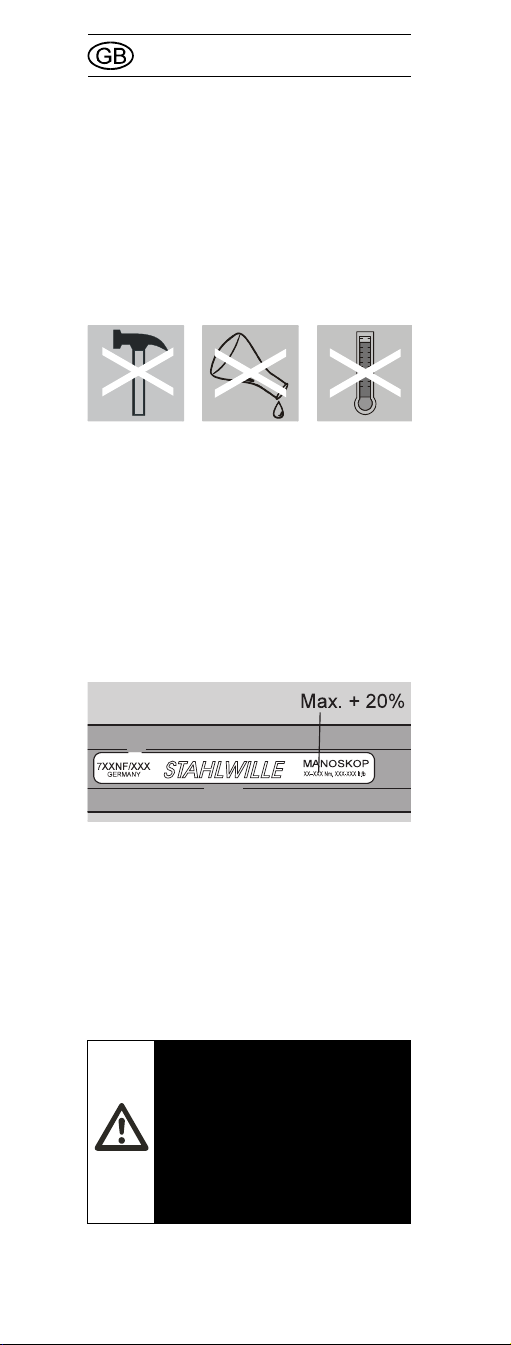
instruments and must be treated with
utmost care. Avoid subjecting the tool to
physical knocks, chemicals or excessive
temperatures beyond the limits given in
these instructions.
Please note that extremes of climate
(cold, heat, humidity) may affect
measuring accuracy.
Avoid overloading the tool by more than
20 % of the maximum permissible load in
the direction of tightening, as otherwise
the Manoskop®may be damaged. After
such an overload, the readings may be
inaccurate in such a way that the user
does not notice.
Avoid loading the tool against the
direction of tightening, as otherwise the
Manoskop®may be damaged.
Use the grip tube –
Manoskop®721 Nf/100
ãCAUTION!
Manoskop®721 Nf/100
may only be used with
the grip tube in position.
Otherwise the readings
will not be accurate.
31
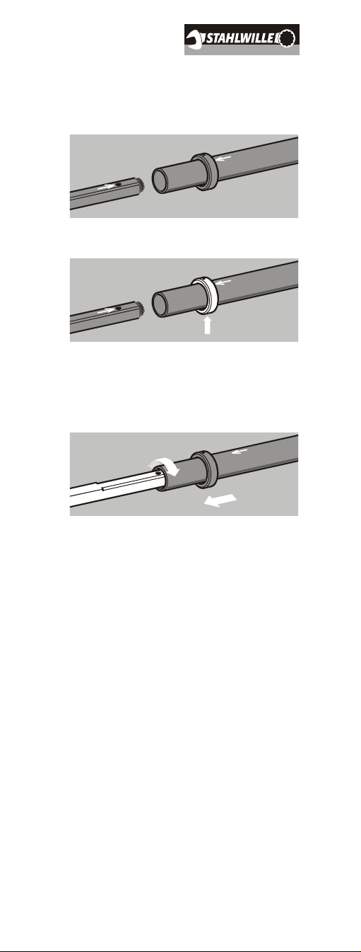
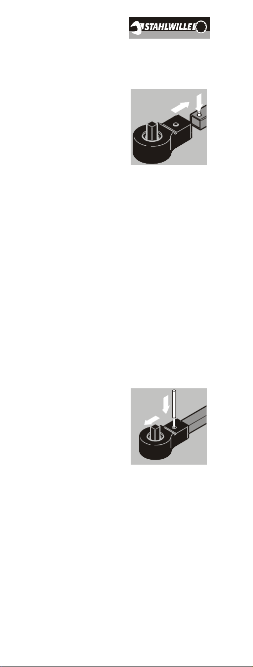
Attaching the grip tube
1. Align the arrows on the Manoskop®
and the grip tube with each other.
2. Press the ring up.
3. Slide the grip tube over the
Manoskop®,until the locking pin
locates. If necessary, rotate the grip
tube slightly back and fore.
4. Check to see that the grip tube is well
located and the pin is in position.

32
Removing the grip tube
1. Press the ring up.
2. Remove the grip tube.
Selecting the inserts and
shell tools
ãCAUTION!
Ensure you have enough
space and can remove
the tube from the
Manoskop®safely
without losing your
balance.
ãCAUTION!
When using inserts on
torque wrenches with a
square drive, ensure
they have been
manufactured to comply
with standards and are
the correct shape and
size for the nut or bolt to
be tightened.
STAHLWILLE inserts
guarantee the
connection will be a
good fit and that the
drive profile will fit
exactly.
33
ãCAUTION!
Please use only shell
tools made by
STAHLWILLE. These
guarantee the correct
lever length, fit
accurately in all
situations and are
designed to have
sufficient strength.
ãCAUTION!
Ensure the maximum
permissible load of the
insert or shell tool used
is not exceeded. This
might be lower than the
maximum cut-out torque
of the torque wrench.
ãCAUTION!
Use of home-made
special tools may be
dangerous. If you need
to manufacture your
own tools, please
contact STAHLWILLE
first.
When using shell tools,
ensure that the locking
pin has located
correctly. Otherwise,
there is a danger of
injury or damage.
ãDANGER!
When using shell tools,
ensure that the locking
pin has located
correctly. Otherwise,
there is a danger of
injury or damage.
34
Remember that the tool has to be of the
correct type and size for the screw or
bolt.
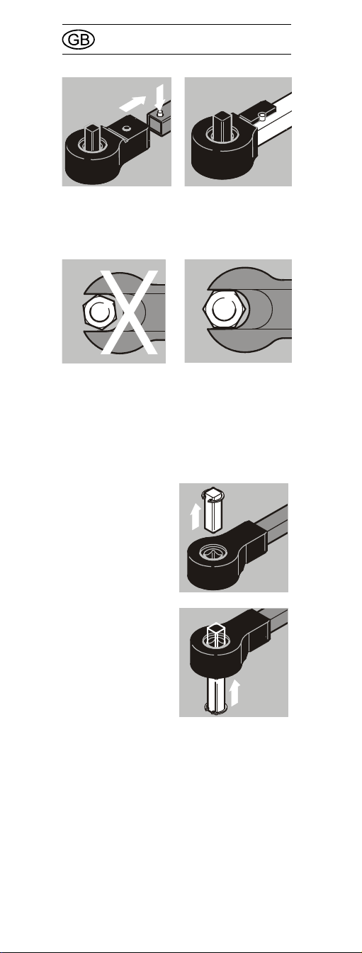
Attaching insert tools
720 Nf/80, 721 Nf/80 und 721 Nf/100
1. Check that the square drive is fitted
to the right side of the torque wrench.
2. If not, push it
through to the
other side.
3. Then push it
back into the
head from the
other side.
4. Slide the insert over the square drive
until it locates.
35
Attaching shell tools –
only 730/80
1. Press down the
spring-loaded
locking pin on
the shaft by
hand.
2. Slide the shell tool over the shaft of
the head of the wrench. Now press
down the shell tool until it comes to
the endstop. Ensure the locking pin
locates in the hole.
3. Check to see that the shell tool is
properly attached.
4. To tighten counter clockwise, turn the
shell tool through 180° before
attaching to the torque wrench.
Exception: If you are using a ratchet
adapter, attach as „normal“ to the
torque wrench and reposition the
square drive (see page 34).
Removing shell tools –
730/80
1. Insert a fine
punch into the
locating hole of
the shell tool
from outside.
Use the punch
to depress the
locking pin.
2. Now remove the shell tool.
Setting the desired torque
The torque level at which the wrench cuts
out is set by moving the scale against the
fixed mark. To do so, turn the smooth
running self-locking knob. Always
approach the desired torque setting from
alower value.
Intermediate settings between two marks
on the scale can be estimated.

36
Proceed as follows:
1. With the 721 Nf/100 it is necessary
to remove the grip tube first (see
page 32). This does not apply to
other models.
2. Turn the knob
clockwise until
the scale shows
avalue lower
than the desired
cut-off value.
3. Then turn the knob counter
clockwise, until the mark for the
desired cut-off value is in the middle
of the scale window.
4. Check the value again. If the setting
is wrong, return to 2.
Controlled counter
clockwise tightening
For reasons of accuracy, these torque
wrenches have been designed to work in
only one direction. The direction is
marked with an arrow.
Controlled counter clockwise tightening
is possible by turning the Manoskop®
over.
For controlled counter clockwise
tightening using the Manoskop®
720 Nf/80, 721 Nf/80 und 721 Nf/100 in
the turned over position, the square drive
must first be pushed through to the upper
side and refitted from the underside
(see page 34).

37
For controlled counter clockwise
tightening using the Manoskop®730/80,
the shell tools have to be rotated through
180°. Exception: If you are using a
ratchet adapter, attach it to the
Manoskop®in the "normal" manner.
Then push the square drive out through
the upper side and reinsert it from the
underside (see page 34).
Uncontrolled loosening of
nuts & bolts ...
..., for example during a tightening
operation, is possible if the Manoskop®is
turned over.
ãCAUTION!
Never exceed a limit of
120 % of the maximum
scale reading. Do not
use the tool for
loosening rusty nuts
and bolts. This may
cause damage to the
torque wrench. After
such an overload, the
readings may be
inaccurate in such a way
that the user does not
notice.

38
Using the torque wrench
Only apply force to the Manoskop®via its
handle. Hold the handle in the middle.
Apply force at a tangent to the swivel
radius and at right angles to the axis of
the nut or bolt.
Pull steadily and without any interruption,
particularly during the final phase, until
you feel a jerk and hear a click. The
torque level set on the scale has now
been reached.
ãDANGER!
Caution! Before you use
the tool, check that the
cut-off value has been
set correctly and that
the insert or shell tool is
correctly fitted.
Manoskop®721 Nf/100
may only be used with
the grip tube in position.
Ensure the locking pin
has correctly located.
Apply the wrench in
such a way that the tool
cannot slip off the head
of the nut or bolt.
Otherwise, there is a
danger of injury or
damage.

39
As soon as the torque wrench has cut
out, it is ready for the next job.
Maintenance
The internal mechanisms of the torque
wrench are subject to normal wear and
tear under operating conditions. For this
reason, the accuracy of the cut-out
should be checked at regular intervals.
Unless otherwise indicated in the user's
internal regulations (e.g. test equipment
inspection to ISO 9000 et seq), an
inspection must take place after approx.
5000 operations or every 12 months,
whichever is the shorter. The time frame
(12 months) starts with the first usage.
If inspection shows that there is a
deviation, the torque wrench must be
adjusted.
The inspection and adjustment must be
carried out in accordance with
DIN EN ISO 6789.
Checking the accuracy of
the cut-off value
Atorque tester of sufficient capacity and
accuracy is required for the inspection.
If you have access to such a tester, you
may inspect the Manoskop®yourself.
Suitable torque testers are available from
STAHLWILLE. It is also possible for
STAHLWILLE to test the Manoskop®for
you.
ãCAUTION!
Important! Once the
wrench has cut out,
never apply more
pressure! You should
therefore not pull too
fast in case you cannot
stop the motion quickly
enough when you hear
the click.

40
To carry out the test, proceed as follows:
1. Set the torque wrench to the highest
scale reading.
2. Operate the torque wrench five times
ensuring it cuts out properly each
time.
3. Set the torque wrench to 20 % of the
maximum scale reading.
4. Operate the torque wrench five times
on the torque tester. Check to see
that the readings shown on the
torque tester are not more than
4.15 % greater and not more than
3.85 % smaller than the value set on
the torque wrench.
5. Set the torque wrench to 60 % of the
maximum scale reading.
6. Operate the torque wrench five times
on the torque tester. Check to see
that the readings shown on the
torque tester are not more than
4.15 % greater and not more than
3.85 % smaller than the value set on
the torque wrench.
7. Set the torque wrench to the highest
scale reading.
8. At this setting, operate the torque
wrench five times on the torque
tester. Check to see that the readings
shown on the torque tester are not
more than 4.15 % greater and not
more than 3.85 % smaller than the
value set on the torque wrench.
ãCAUTION!
Important note on the
accuracy of the
readings: Once the
wrench has cut out,
never apply more
pressure! You should
therefore not pull too
fast in case you cannot
stop the motion quickly
enough when you hear
the click.
41
If the tests show that there are deviations
greater than the permitted amounts, the
wrench will require readjusting.
Adjusting for deviations in
cut-off value
You may return your torque wrench to
STAHLWILLE for adjustment. You will
then receive the tool back with a new
works calibration certificate.
You may adjust the torque wrench
yourself. In this case, however,
STAHLWILLE's accuracy guarantee is
void.
Atorque tester of sufficient capacity and
accuracy is required for the inspection.
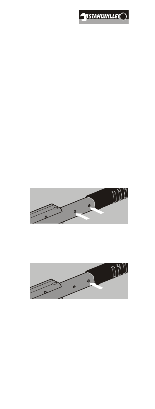
Every Manoskop®has two adjusting
screws inside for readjustment purposes.
These are accessible with an Allen key,
size 2 mm, through two holes in the
housing.
The screw which is closest to the plastic
handle is primarily for adjusting the lower
end of the scale range.
The screw which is closest to the head is
primarily for adjusting the upper end of
the scale range.

42
Each screw has a minor effect on the
adjusting range of the other screw.
To protect the mechanisms from dirt,
these two holes are plugged.
To adjust the wrench, you will need the
torque tester and an Allen key, size
2 mm. Proceed as follows:
1. Remove the two plugs using a sharp
object. Retain the plugs for later use.
2. To adjust the lower end of the range,
insert the Allen key in the hole nearer
to the handle. To adjust the lower
end of the range, insert the Allen key
in the other hole.
3. Turn the Allen key with great care
and very slowly. Turning in a
clockwise direction increases the cut-
out torque level, turning in the other
direction decreases it. The screws
will lock in any position.
4. Once you have made an adjustment
using one screw, check the effect by
testing the cut-off value on the torque
tester.
5. Repeat the adjustment of one or both
screws and the testing process until
the deviation has been
compensated.

43
6. Finally, do a thorough test again.
Proceed as described under see
„Checking the accuracy of the cut-off
value“ on page 39.
7. Refit the plugs to protect the cut-out
mechanism from dirt and damp.
Replacement plugs are available
from STAHLWILLE.
Cleaning the
Manoskop®
ãCAUTION!
If you cannot
compensate for the
deviation within the
prescribed tolerances
using the method
described here, it is
likely that the cut-out
mechanism is damaged.
Such defects can only
be repaired if the torque
wrench is dismantled.
Contact STAHLWILLE in
such cases.
ãCAUTION!
Please use only white
spirit. Other chemical
substances may damage
the plastic components.

44
Accessories
For all models
•Inserts for square drives for all usual
screw head types and sizes.
For STAHLWILLE Standard
Manoskop®730/80
•Sockets
•ratchet adapters
•square shell tools
•open-jaw shell tools
•ring shell tools
For inspection and readjustment
purposes
•Electronic torque testers
Services
•repairs
•testing and readjusting (incl.
accuracy guarantee and new works
calibration certificate)
Disposal
When the tool finally has to be disposed
of, please observe your local
environmental protection laws. The
handle is made of soft PVC.
Other manuals for Standard Manoskop 720 Nf/80
1
This manual suits for next models
3
Table of contents
Other Stahlwille Power Tools manuals

Stahlwille
Stahlwille MANOSKOP 721 Quick User manual

Stahlwille
Stahlwille Standard Manoskop 720 Nf/80 User manual

Stahlwille
Stahlwille Manoskop 71/80 User manual

Stahlwille
Stahlwille MANOSKOP 714 User manual

Stahlwille
Stahlwille 701 User manual

Stahlwille
Stahlwille MANOSKOP 721 Quick User manual

Stahlwille
Stahlwille MANOSKOP 714 User manual

Stahlwille
Stahlwille Manoskop 721/5 User manual

Stahlwille
Stahlwille 701 User manual

Stahlwille
Stahlwille MANOSKOP 730a/10 Quick User manual


