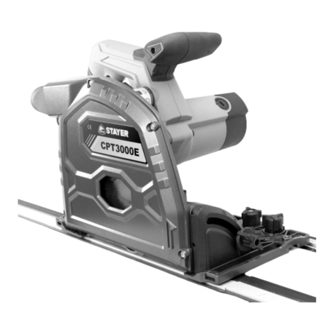
stayer CPT3000E User manual

www.grupostayer.com
Área Empresarial Andalucía - Sector 1
C/ Sierra de Cazorla, 7
28320 - Pinto (Madrid) SPAIN
Email: sales@grupostayer.com
Email: info@grupostayer.com
CPT3000E
Manual de instrucciones
Istruzioni d’uso
Operating instructions
Instructions d´emploi
Manual de instruções
ES
IT
GB
FR
P

4
17
19
8
3
12
15
18
21
23
16
14
5
1
20
2
4
7
6
8
7
Fig. A
Fig. B

6
7
7
8
13
9
10
Fig. 2
Fig. 1
Fig. C
10
11
17
19
23
9
21
11
22 22
8
Fig. 3
23
24

Fig. 4
15 23
Splinter
guide
B
A
5
21
21 22

CPT3000E
W1400
min-1 2000-5000
Ø
mm Ø 185 x 20
Z 48
45º º0-45
mm 67
mm 47
Kg 5.5
K=3db LPA dB(A) 89
LWA dB(A) 100
K=1.5 m/s2ahm/s25.8
6.1

ENGLISH
6
6
This manual is consistent with the date of manufacture of
your machine, you will nd information on the technical
data of the machine acquired manual check for updates
of our machines on the website: www.grupostayer.com
The plunge saw is intended to cut wood and similar
materials, gypsum and cement-bonded ber materials
and plastic. With compatible special saw blades the
plunge saw can also be used to cut aluminum.
The plunge saw is only to be used with a
specically designed guide rail. Installation in a
dierenct or homemade guide rail or workbench
can cause serious accidents.
WARNING! Read this manual and general
safety instructions carefully before using the
appliance, for your own safety. Your power
tool should only be passed on together with
these instructions.
1. INDEX page
2. ADDITIONAL SAFETY INSTRUCTIONS FOR
PLUNGE SAWS...................................................20
3. Instructions for use......................................... ...21
3.1 Placement tool.....................................................21
3.2 Assembly............................................................. 21
3.3 Description.......................................................... 22
4. Operating instructions....................................22
4.1 Switching ON/OFF......................................... ..... 22
4.2.Setting the cutting depth ..................................... 22
5. Maintenance and service instructions..........24
5.1 Cleaning And Maintenance................................. 24
5.2 Repair service......................................................24
5.3 Warranty ............................................................. 24
5.4 Disposal and recycling.........................................24
6. Regulations.....................................................24
6.1 Technical Data..................................................... 24
6.2 EU declaration of conformity................................25
2. ADDITIONAL SAFETY INSTRUCTIONS
FOR PLUNGE SAWS
- Make sure that the mains voltage matches the
specications on the type plate.
- Persons with restricted physical, sensory or mental
capabilities are not allowed to use the plunge saw
unless they are supervised and instructed by a
guardian.
- Never leave the powered-on saw unattended and keep
them out of reach of children and persons in need of
supervision.
- Do not bring your hands in the cutting area and the saw
blade.
- Keep in mind that even a worn saw blade is still very
sharp. Always grasp the saw blade on the sides. Do not
ing the saw blade and do not drop it.
- Never use the plunge saw with grinding wheels.
- Do not grip underneath the workpiece. The protective
cover cannot protect you from the saw blade under the
workpiece.
- Adjust the cutting depth to the thickness of the
workpiece. It should be visible less than a full tooth
height under the workpiece.
- Do not cut very small workpieces. When cutting round
wood, use a device which secures the workpiece from
twisting. Never hold the workpiece to be cut in your
hand or across your leg. It is important to secure the
workpiece properly to minimise the risk of physical
contact, jamming of the saw blade or loss of control.
- Hold the saw only by the insulated gripping surfaces
when performing an operation
where the cutting tool may come into contact with
hidden power lines or its own device cable. Contact
with a live wire also exposes the metal parts to tension
and leads to an electric shock.
- Use always saw blades in the correct size and with
suitable locating bore. Saw blades that do not match
the mounting parts of the saw will run unevenly and
lead to loss of control.
- Never use a damaged or incorrect outer ange or a
damaged clamping screw. The outer ange and the
clamping screw have been specially designed for your
saw for optimum performance and reliability.
- Start the plunge saw and begin cutting when it reaches
the full idling speed.
- Never brake the saw blade using lateral pressure after
switching it o.
- Set the saw aside only when the saw blade comes to a
standstill.
- Do not expose the saw to high temperatures, humidity
and strong shocks. The saw can be damaged as a
result.
- Hold the saw rmly with both hands and bring your
arms into a position in which you can resist the kickback
forces
CAUSES AND PREVENTION OF KICKBACK
- A kickback is the sudden reaction as a result of a
stuck, jammed or misaligned saw blade which leads
to an uncontrolled saw to be lifted and moved from the
workpiece out in the direction of the operator.
- A kickback can occur when the saw blade gets stuck or
jammed in the saw gap. The saw blade is blocked and
the motor force repels the circular saw in the direction
of the operator.
- A kickback can occur when the saw blade becomes
twisted or misaligned in the saw groove. As a result,
the teeth of the back edge of the saw blade can get
stuck in the surface of the workpiece, whereby the saw
blade is moved out of the saw gap and the saw jumps
back in the direction of the operator.
- A kickback is the result of incorrect or faulty use of the
saw. It can be prevented by appropriate precautions as
described below.
- Hold the saw rmly with both hands and bring your
arms into a position in which you can resist the kickback
forces. Always hold the saw baldes on the sides, never
ENGLISH
7
7
bring the blade in line with your body. In a kickback, the
saw can jump backwards, but the operator can control
the kickback forces if appropriate measures were
taken.
- If the saw blade jams or sawing is interrupted for any
reason, release the ON / OFF switch and calmly hold
the saw in the material until the saw blade stands
completely still. Never attempt to remove the saw from
the workpiece or pull it backwards as long as the saw
blade is moving or a kickback might occur. Find the
cause of the saw blade jam and eliminate them through
appropriate measures.
- When you want to restart a saw that is stuck in a
workpiece, center the saw blade in the saw gap
and check that the saw teeth are not stuck in the
workpiece. If the saw blade jams, it can move out from
the workpiece or a kickback can happen if the saw is
restarted.
- Prop up large panels in order to minimise the risk of a
kickback by a jammed saw blade. Large panels tend to
sag under their own weight. Panels must be supported
on both sides, both in the vicinity of the saw gap as well
as on the edge.
- Do not use dull or damaged saw blades. Saw blades
with blunt or misaligned teeth cause increased
friction, jamming of the saw blade and kickback by an
excessively narrow saw gap.
- Tighten the cutting depth position prior to cutting. If the
settings change while cutting, the saw blade can jam
and a kickback can occur.
- Be especially careful if you perform a “circular cut” in a
hidden area, such as an existing wall. The protruding
saw blade can get blocked in hidden objects while
cutting and cause a kickback.
- Do not place the saw on the workbench or the oor
unless the saw blade is at a standstill. An unprotected,
running saw blade moves the saw against the cutting
direction and cuts whatever is in its way. Thus note the
delay time of the saw.
- For this reason, the saw is not suitable for use in
reverse position as xed equipment.
TABLE SAFETY ICONS
Denotes risk of personal injury or damage to the tool.
Lea este manual
antes de utilizar
el aparato.
Always wear
protective gloves
In accordance
with essential
requirements of the
European directive(s)
Always wear safety
goggles.
“Class II - The machine is double insulated; Earthing
wire is therefore not necessary.
- Do not operate the saw if it is not working properly or
has been damaged. In case of technical problems, do
not attempt to repair it on your own. Contact the service
or have the saw repaired by a professional.
3. Instructions for use
3.1 Placement tool
Carefully remove the tool and all loose items from the
shipping container.
Retain all packing materials until after you have inspected
and satisfactorily operated the machine.
Before setting up, repair or maintenance of
the appliance you must always turn o the
operating switch and pull out the mains plug!
3.2 Assembly
- Before each use check the proper function of all
installation xtures of the plunge saw and only use the
plunge saw if everything works properly.
- Attach the work piece in such way that it cannot move
or bend during work. Line the work piece respectively.
- Always hold the plunge saw with both hands at the
hand grips (3) and (4).
- Always guide the plunge saw forward. Never draw the
plunge saw back!
- Place the plunge saw with the front part of the base
plate (5) on the work piece. Guide the plunge saw only
against the work piece during operation.
- With the correct forward speed you prevent overheating
of the saw blade, and melting when cutting plastics.
Plunge saw feature
Selector switch
Use the selector switch (17) to set the respective operation
mode.
Corte de
inmersión
Corte de
marcado
Cambio de hoja
de sierra
Guide rails and clamps (Fig. 1)
Fixing with the clamps ensures solid grip and safe work.
- Place the guide rail on the work piece and x the guide
rail with the clamps. Slide the bar into the groove of the
guide rail and tighten the clamp with the lever.
- Place the plunge saw on the guide rail. The base plate
has a groove (13), which exactly ts into the guide
ridge of the rail.

ENGLISH
8
8
3.3 Descripción ilustrada
1. On/o switch
2. Lock-o button
3. Main handle
4. Auxiliary handle
5. Base
6. Anti-kickback knob
7. Adjustment knob for guide track
8. Bevel lock knob
9. Depth adjustment knob
10. Depth adjustment stopper
11. Depth scale
12. Blade
13. Slot for track
14. Cutting indicators
15. Cutting width indicators
16. Dust extraction outlet
17. Mode selector
18. Shaft lock
19. Carbon brush cap
20. Electronic speed controller.
21. Guide rail.
22. Clamp.
23. Protection guard.
24. Cutting angle scale.
4. Operating instructions
4.1 Placement and testing
Switching ON/OFF
- Press the switch lock (2) and then the ON/OFF switch
(1) to switch the plunge saw on.
- Release the ON/OFF switch (1) to switch the plunge
saw o.
Notes: Pressing the switch lock (2) unlocks the plunge
cut mechanism at the same time, so that the blade can
be moved downwards. The saw blade emerges from the
protective cover. When lifting the saw the motor slides
back into the initial position.
4.2 Tuning operations
4.2.1. Setting the cutting depth
The cutting depth can be set between 0 - 67 mm:
- Loosen the cutting depth limit stop knob (9) and slide it to
the desired cutting depth according to the graduated scale
(11) to set the cutting depth.
Note: The graduated values on the scale (11) apply for
straight cuts (90° cut).
The guide rail depth adjustment stopper (10) must be
tilted up when using the plunge saw without guide rail.
Only when using the plunge saw with guide rail, the guide
rail depth adjustment stopper is used to compensate for
the thickness of the guide rail.
(Fig 2)
Using the guide rail = guide rail depth adjustment stopper
down.
Not using the guide rail = guide rail depth adjustment
stopper up.
(Fig. 3)Tighten the cutting depth limit stop knob (9). The
motor or respectively the saw blade can now be pushed
down to the set cutting depth.
For a clean, safe cut set the cutting depth in such way that
only max. one saw blade tooth protrudes under the work
piece.
4.2.2. Setting the cutting angle (Fig. 4)
The plunge saw can be swiveled between 0° and 48°:
- Loosen both rotary knobs (8). Swivel the motor to the
desired cutting angle on the cutting angle scale.
- Tighten the rotary knobs (8) again
Always hold the plunge saw with both hands.
Always guide the plunge saw forward. Never
draw the plung saw back!
4.2.3. Determine Cutting line (Fig. 4)
Two cutting lines are marked on the base plate (5) of the
plunge saw.
- Align position A (0 mark on base plate) at the front of the
base plate with your marked cutting line when using the
plunge saw without guide rail for straight cuts.
- For 45° miter cuts align position B (45 mark on base plate)
at the front of the base plate with your marked cutting line.
4.2.4. Straight cuts (90° cut)
Loosen both rotary knobs (8) and swivel the saw to 0°
position on the scale. Tighten the rotary knobs again.
Turn the selector switch (17) to plunge cut function.
- Set the desired plunge depth. Ensure that the
guide rail depth adjustment stopper (10) is up when
using the saw without guide rail.
- To switch on the saw press the switch lock (2) and the
ON/OFF switch (1) and push the motor down. Guide
the saw forward to cut.
4.2.5. Miter cuts (up to 48°)
- First loosen both rotary knobs (8) and swivel the plunge
saw to the desired graduation. Tighten the rotary knobs
again.
- Switch the plunge saw on.
Turn the selector switch (17) to plunge cut function.
- Set the desired plunge depth. Ensure that the guide rail
depth adjustment stopper (10) is in up position when
using the saw without guide rail.

ENGLISH
9
9
To switch the saw on press the switch lock (2) and the ON/
OFF switch (1) and push the motor down. Guide the
saw forward to cut.
The cut indicator (14) shows the cutting path for 90°
and 45° miter cuts (without using the guide rail).
4.2.6. Marked cutting
Turn the selector switch (17) to marked cut
function.
- Press the switch lock (2) and push the motor down.
The casing stops in 2.5 mm cutting depth position.
Note: The marking line should be aligned with cutting line
A (0 mark).
4.2.7. Plunge cuts
- For a straight cut rst loosen both rotary knobs (8)
and swivel the plunge saw to 0° position on the scale.
Tighten the rotary knobs again.
Turn the selector switch (17) to plunge cut function.
- Set the desired plunge depth. Ensure that the guide
rail depth adjustment stopper (10) is up if not using the
guide rail.
- Press the switch lock (2) and the ON/OFF switch (1)
and push the motor down. Guide the saw forward to
cut.
Note: To prevent the saw from kicking back during plunge
cuts follow these steps:
- Always place the plunge saw with the rear edge of the
base plate (5) against a xed limit stop.
- Hold the plunge saw in both hands and slowly lower
the saw blade.
- The cutting width marks (15) show the most foremost
and rearmost cutting points of the saw blade (Ø 185
mm) at maximum cutting depth and when using the
guide rail.
4.2.8. Replacing the saw blade
Before any maintenance work always switch o
the plunge saw and disconnect from mains
power.
- Loosen both rotary knobs (8) and swivel the plunge saw
to 0° position before changing the saw blade. Tighten
the rotary knobs again.
- Set the selector switch (17) to the change saw
blade icon.
- Press the switch lock (2) down and push the motor
down.
- Press and hold the spindle arrester down.
- Use a 5 mm Allen key to turn the screw at the saw
blade slightly clockwise or counter-clockwise until the
spindle clicks into place.
- Use the Allen key to loosen the screw counter-
clockwise. Remove the outer ange and the saw blade.
- Clean both anges and replace the saw blade.
Note: The rotation direction arrows of saw blade and saw
must be aligned!
- Replace the outer ange in such way that the slaving
pins sit in the recesses of the inner ange.
- Press and hold the shaft lock b utton and tighten the
screw. Press the switch lock (2) for the casing to swivel
up again.
4.2.9. FINE ADJUSTMENT OF PLUNGE SAW PLAY ON
GUIDE RAIL
The play of the base plate on the guide rail can be reduced
to minimum with the ne adjustment screws (7).
- Loosen the ne adjustment screws counter-clockwise.
- Turn both ne adjustment screws (7) clockwise to
minimize the play between base plate and guide rail, if
necessary.
- Fasten the ne adjustment screws clockwise.
4.2.10. CONNECTING RODS FOR GUIDE RAILS
- To connect both guide rails slide the rst connecting
rod from the bottom into the groove of the guide rail.
- Slide the other connecting rod into the second groove.
- Use the 3 mm Allen key to tighten the stud screws to
the limit stop to connect the rails.
4.2.11. GUIDE RAIL SPLINTER GUARDS
The guide rails come with a splinter guard (black protruding
rubber lip). The splinter guard should be cut to size before rst
use. The splinter guard ensures a tear-free cut, since the wood
bers at the top of the work piece are torn without splinter guard.
This is due to the saw blade teeth being directed upward.
After cutting the splinter guard to size it also shows the precise
cutting path of the saw blade.
- Mark a cutting line on the work piece and align the guide rail
exactly with this cutting line.
- Fix the guide rail with clamps on the work piece.
- Set the selector switch to marked cut function. Set the
plunge saw speed to 6.
- Place the plunge saw at the rear end of the guide rail.
- Switch the plunge saw on and push the saw down. Cut the
splinter guard continuously over the entire length. The edge
of the splinter guard now exactly matches the cutting edge.
4.2.12. KICKBACK STOP
The kickback stop is designed to prevent operator injuries
due to kickback.
When working with the guide rail the kickback stop (6)

ENGLISH
10
10
automatically clicks into place on the base plate as
soon as the base plate is placed on the guide rail. The
kickback stop (6) counteracts the movement if you try to
guide the plunge saw on the guide rail back or if the saw
kicks back, e.g. due to the saw blade jamming.
- Turn the spring-loaded screw of the kickback stop (6)
towards 0 to manually unlock. Now the saw can be
moved forward and back.
- Release the spring-loaded screw for the kickback stop
to click into place on the guide rail again.
After a kickback always check the guide rail for damages
and dispose of a damaged guide rail to prevent accidents.
4.2.13. PLUNGE CUT WITH GUIDE RAIL
- Hold the plunge saw with both hands at hand grips (3)
and (4).
- Switch the plunge saw on and wait until it runs on full
speed.
- Push the saw slowly down and guide the saw towards
the plunge position.
Note: The cutting width markings (15) at the side of the
protective cover show the foremost and rearmost cutting
points of the saw blade at maximum cutting depth when
using the guide rail and a 165 mm diameter saw blade.
5. CLEANING AND MAINTENANCE
Attention !Before performing any work on the
equipment, pull the power plug.
5.1. Cleaning
- Keep the ventilation slots of the machine clean to
prevent overheating of the engine.
- Regularly clean the machine housing with a soft cloth,
preferably after each use.
- Keep the ventilation slots free from dust and dirt.
- If the dirt does not come o use a soft cloth moistened
with soapy water.
Never use solvents such as petrol, alcohol,
ammonia water, etc. These solvents may
damage the plastic parts.
5.1.1. Checking and replacing the carbon brushes
The carbon brushes must be checked on a regular basis.
- In case of wear, replace both carbon brushes at the same
time.
- Mount the carbon brush holders.
- After mounting new carbon brushes, let the machine run at
no load for 15 minutes.
Use only the correct type of carbon brushes.
5.1.2. Lubrication
- From time to time, apply a drop of oil to the thread of
the lock screw (17).
5.2. Repair service
Our after-sales service responds to your questions
conceming maintenance and repair ofyour product as well
as spare parts.
Exploded views and information on spare parts can also
be found under: info@grupostayer.com
Our customer consultants answer your questions
conceming best buy, application and adjustment of
productsand accessories.
5.3. Warranty
Warranty card
lncluded in the documentation that accompanies this
equipment, you should nd the warranty card. You should
ll out the card completely and retum to vendar with a copy
of purchasing receipt or invoice and you should receive a
receipt.
Note: lf you cannot nd the warranty card within
the documentation,youmust ask for it through your
supplier.
The warranty is limited only to manufacturing defects and
expire if pieces have been removed or manipulated or
repaired otherthan themanufacturer.
5.4. Disposal and recycling
The machine, accessories and packaging should be
sorted for environmental-friendly recycling.
OnlyforEC countries:
Do not dispose of power tools into household waste!
According the European Guideline 2002/96/
EC for Waste Electrical and Electronic
Equipment and its implementation into national
right,power tools that are no longer usable
must be collected separately and disposed of
in an environmentally correct manner.
Subject to change wlthout notlce.
6. Regulations
6.1 Technical Data
= Rated power input
= Load speed
= Disc Diameter

ENGLISH
11
11
45º =Cutting capacity
= Cutting capacity 90º
= Cutting capacity 45º
= Weight
LWA = Sound power level
LPA = Sound pressure level
= Vibration
The values givenarevalid for nominalvoltages [U]230/240
V-50/60 Hz - 110/120 V - 60Hz. For lower voltage and
models for specic countries, these values can vary.
Please observe the article number on the type plata of
your machine.The trade names of the individual machines
may vary.
NoiseNibration lnformation
Noise determined according to EN 60745.
The typical sound pressure level of appliance determined
with a lter A product are: Sound pressure level 99 dB(A);
sound power level 100 dB(A). Tolerance K=3 dB.
Wear hearing protection!
Total vibration values (vector sum of three directions)
determined according to EN 60745: Sanding drywal
ah=4 m/s2, K= 1,5 m/s2.
The vibration emission level given in this information sheet
has been measured in accordance with a standardised
test given in EN 60745 and may be used to compare
one tool with another. lt may be used for a preliminary
assessment of exposure.
The declared vibration emission level represents the
main applications of the tool. However if the tool is used
for dierent applications,with dierent accessories or
poorly maintained, the vibration emission may dier.
This may signicantly increase the exposure leveloverthe
totalworking period.
An estimation of the levelof exposure to vibration should
also take into account the times when the tool is switched
o or when it is running but not actually doing the job. This
may signicantly reduce theexposure level over the total
working period.
ldentify additional safety measures to protect the operator
from the eects of vibration such as: maintain the tool
and the accessories,keepthe hands warm, organisation of
work pattems.
6.2 EU declaration of conformity
The undersigned:: STAYER IBERICA, S.A.
With address at:
Calle Sierra de Cazorla, 7
Área Empresarial Andalucía - Sector 1
28320 PINTO (MADRID)
Tel.: 902 91 86 81
CERTIFIES
That the machine:
Type: SIERRA CIRCULAR
Models: CPT3000E
I declare under our responsibility that the product
described under “Technical Data” is in accordance with
the following standards or standardized documents: EN
60745-1, EN 60745-2-5, EN 55014-1, EN 55014-2, EN
61000-3-2, EN 61000-3-3, de acuerdo con las regulacio-
nes 2006/42/CE, 2011/65/EU, 2014/30/EU.
September 14, 2016
Ramiro de la fuente
Director Manage

www.grupostayer.com
Área Empresarial Andalucía - Sector 1
C/ Sierra de Cazorla, 7
28320 - Pinto (Madrid) SPAIN
Email: sales@grupostayer.com
Email: info@grupostayer.com
Other manuals for CPT3000E
1
Table of contents
Other stayer Saw manuals

stayer
stayer CP190 User manual

stayer
stayer SN1435B User manual

stayer
stayer SS210 User manual

stayer
stayer CM230K User manual

stayer
stayer SC241W User manual

stayer
stayer CP L18 User manual

stayer
stayer CP190B User manual

stayer
stayer SC 250W PRO User manual

stayer
stayer SCR216W User manual

stayer
stayer TD355W User manual

stayer
stayer CPT3000E User manual

stayer
stayer SS L12 User manual

stayer
stayer SC250IW User manual

stayer
stayer SC250W User manual

stayer
stayer SCR 255 CW User manual

stayer
stayer CP 125 User manual

stayer
stayer OLMO G1-250 User manual

stayer
stayer SCP 125 DIAMANT User guide

stayer
stayer SC210BW User manual

stayer
stayer SCR315W User manual