stayer TD355W User manual

www.grupostayer.com
TD355W
Operating instructions
GB
Área Empresarial Andalucía - Sector I
Calle Sierra de Cazorla nº7
C.P: 28320 Pinto (Madrid) SPAIN
Email: sales@grupostayer.com
Email: info@grupostayer.com
Manual de instrucciones
ES


Potencia
Giros en vacío
Profundidad de corte:
- A 90º
- A 45º
Dimensión del disco
Peso
2200 W
-1
1300 min
132 mm
120 x 120 mm
180 x 100 mm
105 mm
90 x 90 mm
90 x 120 mm
355 x 3 x 25,4 mm
23.5 kg
CARACTERÍSTICAS TÉCNICAS
TECNHICAL CHARACTERISTICS
No load speed
Cutting capacity, max:
- At 90º
- At 45º
Blade size
Weight
Power input 2200 W
-1
1300 min
132 mm
120 x 120 mm
180 x 100 mm
105 mm
90 x 90 mm
90 x 120 mm
355 x 3 x 25,4 mm
23.5 kg

1
01.
03.
15.
02.
06.
05.
10.
11.
13.
14.
04.
12.
09.
07. 08.

ESPAÑOL
2
2
01. Cierre de transporte
02. Alojamiento de llave
03. Motor
04. Tope de profundidad y tuerca de bloqueo
05. Palanca de bloqueo de tope
06. Tope con escalas de 45º desplazable en ambas
direcciones
07. Apoyo de mordaza
08. Cadena para bloqueo en transporte
09. Manivela de mordaza
10. Palanca de liberación de mordaza
11. Resguardo de disco en dos piezas
12. Gancho (para la cadena de bloqueo para
transporte)
13. Visor transparente de resguardo
14. Bloqueo del eje
15. Conmutador encendido / apagado
REGLAS ESPECÍFICAS DE SEGURIDAD.
1. Siempre asegure la pieza de trabajo
adecuadamente con la mordaza. Nunca
sujete la pieza de trabajo con la mano o haga
cortes sin sujeción.
2. Cuando apriete la mordaza (en el sentido de
las agujas del reloj) asegúrese que la Fig. 10
está en la posición adecuada. De otra
forma la pieza de trabajo no estará sujeta con
seguridad.
3. Nunca intente ajustar, abrir o cerrar la mordaza
mientras la sierra está en funcionamiento.
4. Mantenga las manos y el cuerpo alejados del
área de trabajo y del disco. Nunca intente
alcanzar objetos alrededor, por debajo o a
través de la sierra.
5. Compruebe el protector de sierra inferior
después de cada uso. No opere con la sierra si
el protector inferior no se mueve libremente y se
cierra instantáneamente.
6. Nunca fije la cubierta inferior en la posición
abierta.
7. Compruebe las condiciones de operación de
cárter. Si el cárter no está funcionando
correctamente debe ser revisado antes de su
uso. El cárter puede que no funcione
correctamente debido a las partes dañadas
por residuos pegajosos o por acumulación de
desechos.
8. No utilice discos abrasivos con esta
herramienta. Esta herramienta está
específicamente diseñada con discos de widia
para corte de metal.
9. Siempre utilice discos del tamaño correcto y
bien afilados. Las cuchillas que no coincidan
con la carcasa del disco girarán de manera
excéntrica causando la pérdida de control del
disco.
10. Nunca utilice utensilios o piezas que no hayan
sido fabricados por el fabricante, o que estén
dañados. Estos han sido específicamente
diseñados para esta tronzadora, para un mayor
rendimiento y seguridad en la operación.
11. Siempre compruebe la máxima velocidad de
corte de la sierra y asegúrese que siempre
supera la velocidad de la herramienta
(1300/min)
12. No utilice discos dañados o desafilados. Puede
darse el retroceso.
13. Tenga cuidado de no torcer u obligar al disco.
La sierra se dañará.
14. Mantenga la herramienta en una superficie de
agarre aislada cuando vaya a manejar y
operar con la misma y pueda entrar en
contacto con cables ocultos, o con su mismo
cable. El contacto con un cable puede
exponer las partes metálicas de la herramienta
y crear una descarga al operario.
RETROCESO
Si el disco se tuerce o se desalinea durante el corte, los
dientes posteriores de la hoja podrán clavarse
excesivamente en la superficie de la pieza de trabajo,
lo que podrá causar que el disco salte de su lugar o
que expulse la pieza de trabajo de la herramienta a
gran velocidad y dañe al operador. El retroceso es el
resultado de un mal uso de la herramienta o de un
incorrecto procedimiento de trabajo. Esto se puede
evitar tomando las precauciones que se explican
abajo:
A. Mantenga firmemente agarrada la tronzadora
y posicione el brazo y su cuerpo de tal modo
que le permita resistir las fuerzas de retroceso.
Las fuerzas de retroceso pueden ser
controladas por el operador, si se siguen las
precauciones adecuadas.
B. Cuando el disco se bloquea, o se interrumpe el
corte por cualquier motivo, libere el gatillo y
mantenga la tronzadora inmóvil hasta que el
disco se pare completamente. Nunca intente
quitar el disco mientras esté en funcionamiento
ya que puede darse el retroceso. Investigue y
corrija las acciones que hayan causado tal
situación.

ESPAÑOL
3
3
C. Cuando se reinicie la operación en cortes que
ya estaban empezados, centre el disco en el
mismo corte y compruebe que el diente no se
queda enganchado al material. Si el disco se
para, puede que pase por encima de la
superficie o que se dé el retroceso de la pieza
de trabajo mientras que la sierra se reinicia.
D. Soporte de piezas grandes para minimizar el
riesgo de retroceso. Las piezas grandes tienden
a hundirse ante su propio peso. Se deben poner
soportes debajo de ellas a ambos lados, cerca
de la línea de corte o en el borde de la pieza de
trabajo.
E. No utilice discos de corte dañados. Los discos
dañados pueden producir excesiva fricción,
causando de esta forma el retroceso.
F. El bloqueo debe estar apretado y seguro
mientras se realicen los cortes. Si el ajuste se
libera mientras se corta, pude que se dé el
retroceso o la liberación a gran velocidad de la
pieza de trabajo.
15. Utilice los discos de widia adecuados para
corte de metal.
16. Ate el disco y retenga el perno y las
abrazaderas antes de empezar a trabajar.
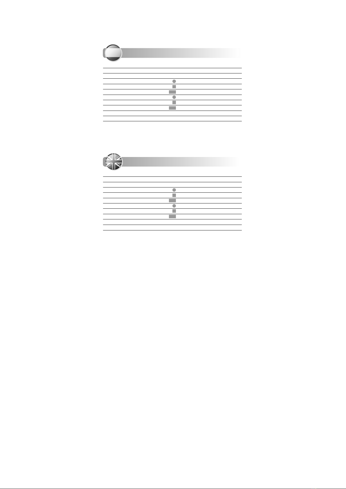
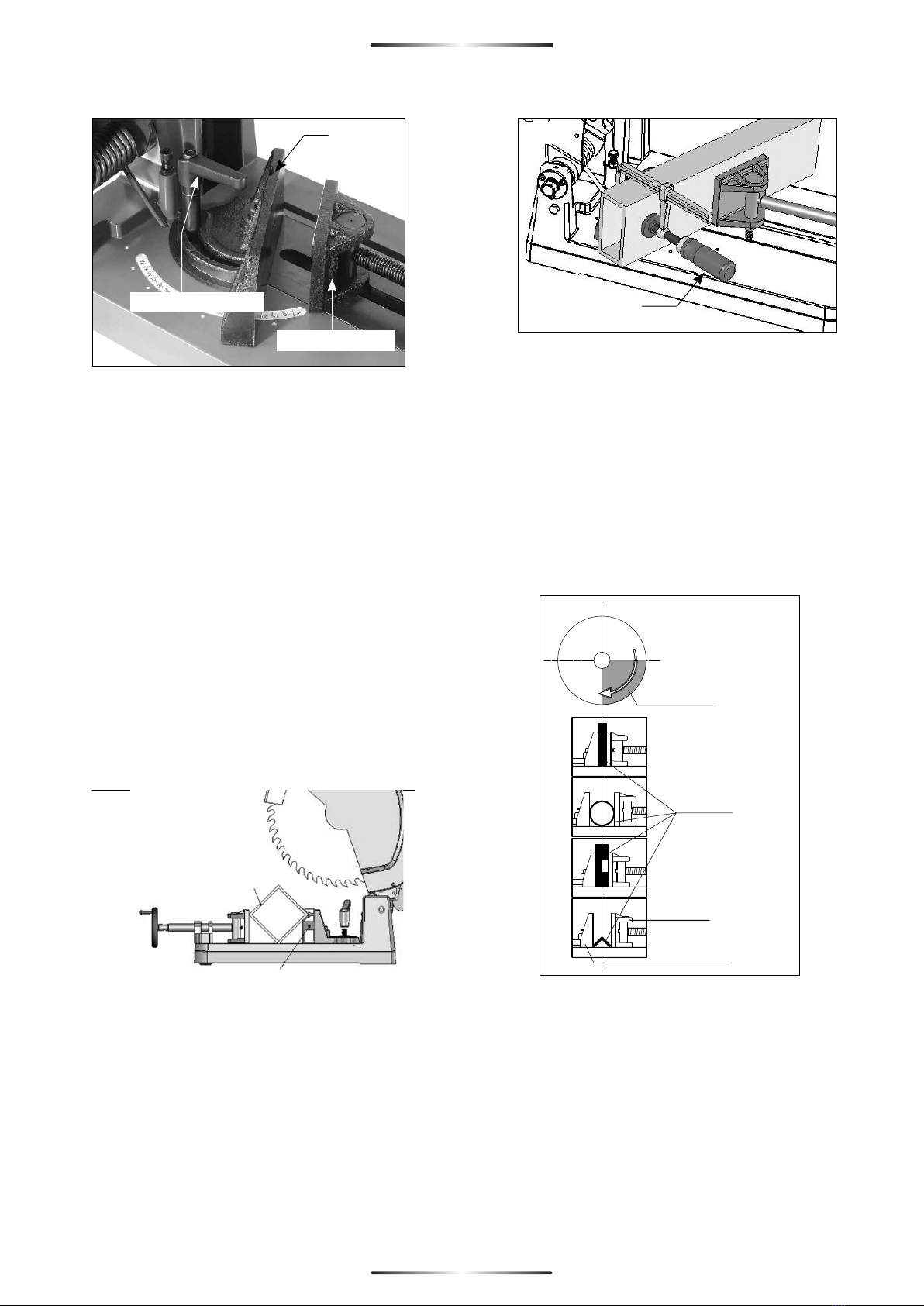
17. Fije la pieza de trabajo correctamente. La pieza
deberá estar recta y firmemente sujeta para
evitar posibles movimientos.
18. Permita que el disco se pare completamente
antes de quitarlo o de asegurar o cambiar el
ángulo de la pieza de trabajo.
19. Compruebe las superficies así como los
laterales y los dientes del disco para liberarlos
de cualquier elemento externo ajeno al corte.
20. Compruebe que el disco no tenga cortes o
cualquier otro defecto antes de operar con el.
Reemplace el disco dañado por uno nuevo
inmediatamente.
21. Nunca arranque la herramienta con la pieza de
trabajo en contra del disco.
22. Permita al motor alcanzar la máxima velocidad
antes de empezar a cortar.
23. No corte material más fino de lo que permite la
máxima capacidad de la herramienta.
24. Después de encender la máquina “ Encendido
(On)” suavemente presione la herramienta
hacia adelante hasta alcanzar la pieza de
trabajo, entonces despacio aumente la presión
requerida para producir la menor cantidad de
residuos.
25. No utilice esta herramienta continuamente más
de 31 minutos.
26. Importante! Después de completar el corte,
levante la cabeza del motor, desenchúfela, y
espere a que el disco se pare completamente
antes de abandonar la herramienta.
27. Nunca trabaje con la herramienta en áreas
donde pueda haber sólidos, líquidos, o gases
flamables. La viruta o fragmentos calientes
pueden causar una explosión.
28. Esta herramienta está diseñada para metales
ferrosos y aluminio exclusivamente. No intente
cortar madera, mampostería, magnesio o
cualquier otro material pirofórico con esta
herramienta.
29. No utilice fluidos o lubricantes con esta sierra.
30. Algunos metales tienen recubrimientos que
pueden ser tóxicos. Tome precauciones extras
para prevenir la inhalación o el contacto con la
piel cuando se trabaje con estos materiales.
Pida información y siga los consejos de su
proveedor.
31. Hay ciertas aplicaciones para las cuales esta
herramienta fue diseñada. El fabricante
recomienda fervientemente que esta
herramienta NO se modifique o que se utilice
para diferentes usos para los que fue diseñada.
Si usted tiene alguna pregunta relativa a las
aplicaciones de la misma NO utilice la
herramienta hasta que lo haya consultado con
su proveedor y éste le haya aconsejado.
Las virutas de metal a menudo suelen estar muy
afiladas y calientes. Nunca las toque con la mano.
Límpielas con un imán o con cualquier otra
herramienta apropiada.
Esta herramienta es para corte húmedo-seco.
Diseñada para cortar materiales ferrosos y no ferrosos.
Esta sierra utiliza discos de 1400rpm o más. No se
recomienda cortar acero ya que acortará
drásticamente la vida del disco ni materiales blandos
como la madera.
DESEMBALAJE
Cuidadosamente saque la herramienta y todas las
piezas del embalaje.
Conserve todos los materiales hasta que compruebe
que están todos y hay a trabajado con la máquina.l

ESPAÑOL
4
4
NOTA: Se debe montar un disco apropiado a la
máquina antes de operar. Ver la sección del manual
“Instalación del disco”
CONTENIDO DE LA CAJA
1.Sierra de corte de metal
No trabaje con la herramienta hasta que lea y
comprenda las instrucciones completas del manual.
<INSTALACIÓN DEL DISCO DESCONECTE LA
HERRAMIENTA DE LA CORRIENTE.
Nota: Utilice el disco adecuado a las indicaciones
facilitadas en el punto “RETROCESO”
ATENCIÓN: Evite el contacto con los dientes del disco
para evitar daños personales.
1. Asegúrese que la cabeza del motor está
completamente levantada, bloqueada y
desconectada. Quite los 4 tornillos que sujetan
la cubierta y quítenla.
2. Oriente la pestaña interior de manera que el
lado correcto esté hacia fuera.
3. Llevando finos guantes de trabajo que protejan
sus manos, cuidadosamente sostenga el disco
por la parte de arriba y póngalo boca abajo en
la posición de la pestaña interior. Debe primero
deslizarse por las cubiertas inferiores y
posteriormente por el eje Asegúrese que los
dientes están hacia afuera. (Si tiene alguna
duda sobre la orientación del disco,
compruebe la leyenda estampada en la
cubierta del disco).
4. Posicione el disco en la posición adecuada al
giro
5. Utilice la llave que se le facilita de 8mm en el
tornillo Presione el bloqueo (ver figura 2) y gire
el tornillo con la llave hasta que quede
ajustado.
6. Una vez que esté bloqueado, apriételo
girándolo en sentido de las agujas del reloj.
7. Finalmente reemplace la cubierta del disco y
apriete los 4 tornillos.
<QUITAR EL DISCO
1. Asegúrese que la cabeza del motor está
completamente levantada, bloqueada y
desconectada. Quite los 4 tornillos que sujetan
la cubierta y quítenla.
2. Una vez que la cubierta se ha quitado, utilice la
llave que se le facilita de 8mm en el tornillo,
presione el bloqueo y gire el tornillo con la llave
hasta que quede ajustado.
3. Una vez que esta ajustado, gírelo en sentido
contrario a las agujas del reloj para aflojarlo.
4. Quite el bloqueo con la arandela plana y el
tornillo (Primero fíjese en la orientación)
5. Llevando guantes finos para la protección de
las manos, cuidadosamente sujete el disco por
la parte de arriba y quítelo de la herramienta.
<UTILIZACIÓN DEL TORNILLO Y DE LA GUÍA
Atención: Utilice la mordaza siempre y sin excepción.
Si la mordaza no se puede fijar adecuadamente a la
pieza de trabajo en cuestión, no lo utilice para cortar.
Cortar sin esta seguridad puede causar el retroceso y
situaciones peligrosas.
Siempre asegure la pieza de trabajo en la posición
más estable posible. Asegúrese que la sierra se fija a la
pieza de trabajo en el centro de la guía.
La guía gira para crear cortes hasta 45 grados y el
tornillo gira libremente para alcanzar el ángulo de la
guía.
Para ajustar la guía y crear cortes angulares:
1. Afloje la maneta girándola en sentido de las
agujas del reloj. Presione con el pulgar mientras
tira hacia arriba y en contra del muelle para
liberarlo de su posición.
2. Gire la guía hasta el ángulo deseado y sujételo
firmemente. Se pueden ver varias marcas que
ubican los ángulos más utilizados entre ángulos
de 0 a 45 grados que pueden ser utilizados. Ver
Fig. 4
Fig.2
Bloqueo
Fig.3
Perno
Arandela
Flangia externa
disco
Flangia interna

Gato de apriete
Fig.6
Guía
Plato mordaza
Palanca fijación
ESPAÑOL
5
5
Nota: haciendo un corte de 45º es posible que el disco
no sea capaz de cortar completamente el material.
En este caso, utilice el espaciador para mas de 31mm
de grosor en contra de la guía para traer la pieza de
trabajo hasta el arco del disco
<UTILIZANDO EL ESPACIADOR OPCIONAL
El espaciador tiene diferentes usos.
1. Para hacer cortes remítase a la Fig. 5. Para su
correcta colocación.
2. Haciendo un corte de 45º es posible que no el
disco no sea capaz de cortar completamente
el material. En este caso, utilice el espaciador
de al menos 31mm de grosor en contra de la
guía para traer la pieza de trabajo hasta el arco
de la sierra.
3. Para instalar el espaciador simplemente
atorníllelo a la guía con el V-Channel in la
posición más
Nota: Cuando sea posible, siempre haga cortes
rectos. Esto es: rote la guía en sentido de las agujas
del reloj tirando del borde hacia usted.
PRECAUCIÓN: Un fallo en la utilización del gato de
apriete puede hacer que la pieza de trabajo se afloje,
produciendo una peligrosa situación.
Una vez que la guía está situada en la posición
deseada, posiciones la pieza en contra de la misma y
apriete el tornillo. La posición de la pieza de trabajo es
muy importante para realizar una operación segura.
Por favor, ver fig. 7 debajo para posicionar
correctamente las diferentes piezas de trabajo.
Siempre mantenga presente que el disco gira en
sentido contrario a las agujas del reloj, empujando de
esta forma la pieza de trabajo en contra de la guía.
<OPERACIÓN CON EL TORNILLO
El tornillo tiene un método de liberación sencillo.
1. Posicione la pieza de trabajo en contra de la
guía en la posición más segura posible.
2. Tire para liberar la palanca hacia la izquierda
para liberar a su vez el tornillo. Ver fig. 8.
3. Deslice el tornillo para ajustar la pieza de
trabajo.
4. Tire de la palanca liberada hacia la derecha
para ajustar.
5. Apriete el tornillo utilizando la manivela.
Fig.5
Espaciador
Fig.4
Fig.7
Área de corte
Pieza de trabajo
Plato mordaza
Guía rápida
de ajuste

Fig.10
Fig.9 Interruptor On / Off
Liberar Ajustar Fig.8
ESPAÑOL
6
6
<AJUSTAR LA PROFUNDIDAD DEL CORTE-
DESCONECTE LA MÁQUINA DE LA CORRIENTE
ELÉCTRICA.
La profundidad de corte está programada desde la
fábrica y puede que no requiera mas ajuste. Si la sierra
está desmontada o por cualquier otra razón, la
profundidad de corte deberá ser ajustada como se
explica más abajo:
1. Eleve el motor hasta el tope.
2. Afloje la tuerca de seguridad para ajustar la
profundidad de corte al nivel deseado
utilizando la llave de 6mm. Ver fig. 1
3. Vuelva a apretar la tuerca de seguridad.
<ARRANQUE Y PARADA DE LA HERRAMIENTA.
Asegúrese que la corriente eléctrica es la misma que
se especifica en la herramienta y que el interruptor
está “APAGADO” antes de conectarla a la corriente
eléctrica. Ver Fig. 9.
Para arrancar la máquina primero presione el
pulsador para arrancar el motor y permita que el
mismo alcance la máxima velocidad, posteriormente
presione la leva del cárter y permita la cabeza del
motor alcanzar la pieza de trabajo. Libere el pulsador
para parar el motor.
<ELIMINACIÓN DE VIRUTAS.
Esta herramienta de corte seco-húmedo tiene in
recolector interno de virutas. Ver fig. 10
Cuando el recolector está lleno, las virutas deberán
quitarse, para hacer esto primero desconecte la
herramienta de la corriente eléctrica.
Desatornille la presilla de seguridad girándola en
sentido de las agujas del reloj y entonces retire la
bandeja. Para colocarlos es lo contrario.
Las virutas recién cortadas puede que estén afiladas y
muy calientes. Ponga cuidado al retirarlas de no
tocarlas con las manos o cualquier otra parte de su
cuerpo. No tire los desechos calientes en la papelera
o donde pueda haber materiales flamables.
<UTILIZACIÓN CADENA DE SEGURIDAD PARA
TRANSPORTE
Para una mayor facilidad en el transporte deberá
utilizarse la cadena de seguridad. Simplemente baje
la cabeza del motor, y enganche la cadena en el
correspondiente enganche de la cabeza del motor.
<PROTECTORES INFERIORES DE LA SIERRA
Estos protectores son un dispositivo muy importante
para su protección. Cada vez que utilice la sierra
asegúrese que los protectores rotan libremente y que
vuelven rápida y completamente a su posición de
cerrado. Antes de cada uso, limpie las virutas que
puedan quedar alrededor del cárter. NO LUBRIQUE
ESTA ÁREA. El cárter tiene una capa seca lubricada
que no necesita ningún tipo de aceite. NUNCA
bloquee la protección del disco en posición abierta.
NUNCA utilice la sierra si no está trabajando.
Si el movimiento de la sierra es lento, llévelo al centro
de servicio mas cercano para que pueda ser
reparado.
<COMO UTILIZAR LA HERRAMIENTA.
NOTA: Acuérdese que a pesar de que esta máquina
parezca similar a una sierra circular con disco
abrasivo, esta máquina requiere mucha menos
presión.
1. Asegure la pieza de trabajo tal y como se
describe en el párrafo “UTILIZACION DEL
TORNILLO Y DE LA GUÍA”. La pieza de trabajo
debe estar recta y firmemente sujeta para
evitar cualquier movimiento antes de que se
complete el corte. Proporcionar el soporte
adecuado para piezas de trabajo largas o
anchas.

Ramiro de la Fuente
Director Manager
ESPAÑOL
7
7
2. Compruebe las cubiertas inferiores para un
normal funcionamiento.
3. Presione el gatillo del interruptor y permita que
el motor alcance la máxima velocidad.
4. Presione la leva del cárter con el pulgar, y
después suavemente baje la cabeza del motor
hasta que entre en contacto con la pieza de
trabajo y empiece a cortar. Recuerde no
permanecer en línea con la sierra. Siempre
proceda cuidadosamente al principio y al final
del corte.
5. Mientras corte, controle la fuerza de bajada. No
es necesario forzar el corte. Deje que la sierra
realice el corte a la velocidad permitida por el
tipo de corte en la pieza de trabajo. Incremente
la presión cuando corte en secciones de la
pieza mas gruesas. Disminuya la presión en
piezas de corte mas finas.
PRECAUCIÓN: SI LA SIERRA SE ATASCA AL HACER EL
CORTE, LIBERE EL GATILLO DEL INTERRUPTOR
INMEDIATAMENTE.
Después de completar el corte, eleve la cabeza del
motor y déjela completamente despejada de la
pieza de trabajo antes de liberar el botón de
encendido. Confirme que la sierra ha quedado
completamente apagada antes de quitar o asegurar
la pieza de trabajo, o cambiar el ángulo de la misma.
<MANTENIMIENTO
Periódicamente sople todos los compartimentos con
un compresor de aire. Todas las partes de plástico
deberán ser limpiadas con un trapo suave y húmedo.
NUNCA utilice disolventes para limpiar las partes de
plástico, pueden dañar el material. Utilice gafas de
seguridad mientras utiliza el compresor de aire.
Se recomienda que por lo menos una vez al año lleve
la herramienta a un servicio técnico, para una
limpieza profundad comprobación. Y lubricación.
<ESCOBILLAS.
Las escobillas son una parte de uso habitual, y se
deben reemplazar cuando llegan a su límite de
desgaste. Cuando llegan a su punto final de desgaste
el motor no funcionará. Si la máquina se para sin razón
aparente puede que sea porque las escobillas
deberán ser cambiadas.
NOTA: Se deberá cambiar el par completo de
escobillas
Para cambiarlas:
Quite los cuatro tornillos y quite la cubierta. Utilizando
los alicates rote el muelle de las escobillas y quítelo, y
deslice la escobilla fuera del porta-escobillas.
Para poner las nuevas, realice el proceso contrario.
NOTA: Si usted simplemente está comprobando las
escobillas, asegurese que se colocan en la misma
posición en la que estaban, si no ocurrirá que en el
periodo de rodaje se reduzca el rendimiento del
motor y aumente el desgaste de las escobillas.
<ACCESORIOS ESTANDAR.
- 8mm llave inglesa
- 6mm llave inglesa
- 4mm llave inglesa
<Si se necesitara reemplazar el cable, esto se
deberá hacer por el fabricante o su agente en su
defecto para evitar peligros.
IEC61029-2-10, EN55014,
EN61000 de acuerdo con las regulaciones 2006/42 CE,
2006/95CE Y 2004/108CE.
DECLARACIÓN DE CONFORMIDAD
Declaramos bajo nuestra responsabilidad, que
el producto descrito bajo “Datos técnicos” está
en conformidad con las normas o documentos
normalizados siguientes:
Muelle tensión
Porta escobilla
Escobilla
parada automática

SPECIFIC SAFETY RULES
Always Secure the workpiece properly
1.
with the vise. Never hold the workpiece
by hand or attempt freehand cuts.
When clamping with the fence in a left-
2.
hand miter (clockwise) The clamp must
b e a u g me nt e d w it h a C - cl a m p .
Otherwise the workpiece will not be
securely held.
Never Attempt to adjust, open or close
3.
the vise while the blade is in motion.
Keep hands and body away from
4.
cutting area and rotating blade. Never
reach around, under or across the
blade.
Check lower guard for proper closing
5.
before each use. Do not operate the
saw if lower guard does not move freely
and close instantly.
Never clamp or tie the lower guard into
6.
the open position.
Check the operation and condition of
7.
the lower guard. If the guard is not
operating properly, it must be serviced
before use. Lower guard may operate
sluggishly due to damaged parts,
gummy deposits, or a buildup of debris.
Do not use abrasive wheels with this
8.
machine. This machine was specifically
designed to use carbide tipped metal
cutting blades.
Always use blades with correct size and
9.
shape arbor holes. Blades that do not
match the mounting hardware of the
saw will run eccentrically, causing loss
of control.
Never use damaged or incorrect arbor
10.
flanges or bolts. The arbor flanges and
bolt were specially designed for your
saw, for best performance and safety of
operation
Always check the maximum rated
11.
speed of the balde and ensure that it
exceeds the speed of the machine
(1300/min).
Do not use damaged or dull blades.
12.
Kickback may result.
Take care to avoid twisting or binding
13.
the blade. The blade will be damaged.
Hold tool by insulated gripping surfaces
14.
when performing an operation where
the cutting tools may contact hidden
wiring or its own cord. Contact with a
“live” wire will make exposed metal
parts of the tool “ live ” and shock the
operator.
KICKBACK:
If the blade becomes twisted or misaligned
in the cut, the teeth at the back edge of the
blade can dig into the top surface of the
workpiece, causing the blade to climb out
of the kerf and jump back toward the
operator and/or eject the workpiece from
the machine at high speed. Kickback is the
result of tool misuse and/or incorrect
operating procedures or conditions and can
be avoided by taking proper precautions as
given below:
Maintain a firm grip on the saw andA.
position your body and arm in a way
that allows you to resist KICKBACK
forces. KICKBACK forces can be
controlled by the operator, if proper
precautions are taken.
ENGLISH
8
8
01.Carriage Lock
02. Wrench storage
03. Motor
04. Depth Stop & Lock Nut
05. Tool-Free Fence Lock
06. Fence with scale swivels 45 degrees
in both directions
07. Vise Plate
08. Transport Lock Chain
09. Crank
10. Vise Release Lever
11. Two-piece Lower Blade Guard
12. Hook (for Transport Lock Chain)
13. See-Through Shield
14. Arbor Lock
15. On / Off Switch

When blade is binding, or whenB.
interrupting a cut for any reason,
release the trigger and hold the saw
motionless in the material until the
blade comes to a complete stop.
Never attempt to remove the saw
from the work while the blade is in
motion or KICKBACK may occur.
Investigate and take corrective
actions to eliminate the cause of
blade binding.
When restarting in half-finished cuts,C.
center the saw blade in the kerf and
check that teeth are not engaged
into the material. If saw blade is
binding, it may walk up or KICKBACK
from the workpiece as the saw is
restarted.
Support large workpieces to minimizeD.
the risk of blade pinching and
KICKBACK. Large workpieces tend to
sag under their own weight. Supports
must be placed under them on both
sides, near the line of cut and near
the edge of the workpiece.
Do not use dull or damaged blade.E.
Dull blades produce a narrow kerf
causing excessive friction, blade
binding, and KICKBACK.
The fence lock lever must be tightF.
and secure before making a cut. If
the adjustment shifts while cutting,
it will cause binding and KICKBACK
or h igh speed eject ion of the
workpiece.
Use only recommended
15. carbide-tipped
metal cutting blades, rated at the
machine’s maximum rated RPM or
higher with correct arbor hole.
Tighten blade retaining bolt
16. and all
clamps before operating.
Secure workpiece properly.
17. Workpiece
should be straight and firmly clamped
to avoid possible movement and
pinching as the cut nears completion.
Allow the blade to come to a complete
18.
stop before removing or securing
workpiece, or changing workpiece
angle.
Check the inside surfaces
19. of the arbor
flanges as well as the sides of the blade
for freedom from any foreign matter.
Check the blade
21. for cracks or other
damage before operation. Replace
c r a c k e d o r d a m a g e d b l a d e
immediately.
Never start the tool
21. with the workpiece
against the blade.
Allow the motor to achieve full speed
22.
before cutting.
Do not cut material thicker than the
23.
maximum capacity of the machine.
After turning tool “ON”,
24. gently push the
tool forward to engage workpiece,
th en slo wly increase pressure a s
required to produce the least amount
of “sparking”.
Do not use this tool continuously more
25.
than 31 minutes.
Important: After completing the cut,
26.
raise the motor head, release power
switch, and wait for coasting blade to
stop completely before leaving the
saw.
Never operate
27. the tool in an area with
flammable solids, liquids, or gases.
Sparks or hot fragments could cause a
fire or explosion.
This tool is designed for ferrous metals or
28.
aluminum only. Do not attempt to cut
wood, masonry, magnesium, or any
other pyrophoric materials with this tool.
Do not use cutting fluids or lubricants on
29.
the blade.
Some metals have coatings which can
30.
be toxic. Take extra care to prevent
inhalation and skin contact when
working with these materials. Request,
and follow, any safety information
available from your material supplier.
ENGLISH
9
9

There are certain applications for which
31.
t h i s t o o l w a s d e s i g n e d . T h e
manufacturer strongly recommends
that this tool NOT be modified and/or
used for any application other than for
which it was designed. If you have any
questions relative to its application DO
NOT use the tool until you have written
the manufacturer and have been
advised.
Metal chips are often very sharp and hot.
Never touch them with bare hands. Clean
up with a magnetic chip collector or other
appropriate tool.
This machine is a Dry-Cut Metal S aw
designed to cut various ferrous and non-
ferrous metals. This saw uses blades that are
rated for 1400 /min or higher. It is not
recommended to cut hardened steel as this
will drastically shorten the life of the blade.
Soft materials such as wood are also not
recommended.
UNPACKING
Carefully remove the tool and all loose items
from the shipping container.
Retain all packing materials until after you
have inspected and satisfactorily operated
the machine.
NOTE: An appropriate blade must be
mounted to the machine before operating.
Refer to t h e s ection o f t h is manual:
“INSTALLING THE BLADE”
CARTON CONTENTS
1. Metal Cutting Saw
DO NOT OPERATE THIS TOOL UNTIL YOU READ
AND UNDERSTAND THE ENTIRE INSTRUCTION
MANUAL.
■INSTALLING THE BLADE -DISCONNECT TOOL
FROM POWER SOURCE.
NOTE: Use blades that have an arbor bore
which can fit, and that are rated for1114/
min or higher.
WARNING: Avoid contact with blade teeth to
prevent personal injury.
Ensure that the motor head is in its fully
1.
r a is e d a n d l o ck ed p o s i ti o n a nd
unplugged. Remove the four screws
which hold on the outer blade cover
and remove the cover.
Orient the inner flange so that the
2.
correct side faces outwards.
Wearing thick work gloves to protect
3.
the hands, carefully hold the blade
from the top and lower it downwards
into position on the inner flange. It must
first slip into place in the lower guards
and then onto the arbor. Make sure
that the teeth point forwards. (If in
doubt of the orientation of the blade,
refer to the legend stamped into the
outer blade cover).
Position the outer blade flange with the
4.
convex side outwards, then the flat
washer and finally the arbor bolt.
Use the supplied 8mm hex wrench on
5.
the arbor bolt. Push in the arbor lock
(See Fig.2.) and rotate the arbor with
the wrench until the lock engages the
blade arbor.
Once the arbor lock is engaged,
6.
tighten the arbor b olt by turning
clockwise.
Finally replace the outer blade cover
7.
and tighten the 4 screws. See Fig.3.
Fig.2
Arbor Lock
ENGLISH
10
10

Fig.3
Arbor Bolt
Washer
Outer Flange
Blade
Inner Flange
■REMOVING THE BLADE -DISCONNECT
TOOL FROM POWER SOURCE.
Ensure that the motor head is in its fully
1.
r a is e d a n d l o ck ed p o s i ti o n a nd
unplugged. Remove the four screws
which hold on the outer blade cover
and remove the cover.
Once the cover is removed, use the
2.
supplied 8mm hex wrench on the arbor
bolt. Push in the arbor lock and rotate
the blade with the wrench until the lock
engages the blade arbor.
Once the arbor lock is engaged, turn
3.
the arbor bolt anticlockwise to loosen.
Remove the arbor bolt, flat washer and
4.
o u t e r b l a d e f l a n g e ( n o t e i t s
orientation).
Wearing thick work gloves to protect
5.
the hands, carefully hold the blade
from the top and lift it upwards and
away to remove.
■USING THE VISE & FENCE SYSTEM
WARNING: The vise must always be used
without exception. If the vise cannot
ad equat ely clamp the workpiece in
question, then do not use this machine to
cut it. Cutting without the vise can easily
lead to kickback and other hazardous
situations.
Always clamp the workpiece in the most
stable position possible. Ensure that the
blade engages the workpiece in the
quadrant behind the center line of the
arbor.
The fence swivels to create miter cuts up to
45 degrees and the vise plate swivels freely
to match the angle of the fence.
To adjust the fence to create miter cuts:
Loosen the miter lock lever by turning
1.
counterclockwise. Press with the thumb
while pulling up against the spring
tension to ratchet the lever.
Rotate the fence to the desired angle
2.
and retighten firmly. There are preset
detents for popular angles, but any
angle between 0 and 45 degrees can
be used. See Fig.4.
Note: Cutting 45 degree miters may shift the
workpiece forward so far that the blade will
not be able to cut fully through the material.
In this case, use a spacer of at least 31mm
thickness against the fence to bring the
workpiece fully into the range of the blade
arc. (The optional V-Jig Block may also be
used for this purpose).
Fence
Vise Plate
lock lever
Fig.4
■Using the optional V-Jig Block
The V-Jig Block has several purposes:
Holding square-section tubing in a tilted
1.
position so that the blade can more
e a s i ly b e g i n a n d f i ni s h t h e c u t .
Otherwise the blade has difficulty
"biting" into the broad, flat face of the
workpiece. See Fig.5.
ENGLISH
11
11

Cutting 45 degree miters may shift the
2.
workpiece forward so far that the blade
will not be able to cut fully through the
material. In this case, the optional V-Jig
Block may be used as a spacer to bring
the workpiece fully into the range of
the blade arc.
To install the V-Jig, simply bolt it to the
3.
fence with the V-channel in the upper
position.
Note: Whenever possible, always make
right-hand miters. That is: rotate the fence
counterclockwise by pulling its left edge
towards you. If a left-hand mite1r of 2
degrees or more is necessary, then a
suitable C-clamp must be used to clamp the
workpiece to the fence on the left-hand
side.See Fig.6.
Fig.5
V-Jig Block
C-CLAMP
Fig.6
WARNING: FAILURE TO EMPLOY A C-CLAMP
ON LEFT-HAND MITERS MAY ALLOW THE
WORKPIECE TO COME LOOSE, CAUSING A
HAZARDOUS SITUATION.
Once the fence is set to the desired angle,
place the workpiece against the fence and
tig h ten t h e vise. The position of th e
workpiece is very important for the safety of
the operator. Please see the Fig.7 below for
the best positions for various workpiece
types. Always keep in mind that the blade
spins counterclockwise which pushes the
workpiece against the fence.
■To operate the vise
The vise is a quick-release type.
Position the workpiece against the
1.
fence in the safest possible orientation.
Flip the release lever to the left to
2.
release the vise shaft from the threads.
See Fig.8.
Slide the vise forward to engage the
3.
workpiece.
Flip the release lever to the right to lock
4.
the threads.
Fully tighten the vice using the crank.
5.
Fig.7
Release Lock Fig.8
ENGLISH
12
12

■REMOVING CHIPS
This dry-cut saw has an internal chip
collector tray. See Fig.10.
When the chip tray is full, the chips must be
cleared. To do this, first shut down and
DISCONNECT TOOL FROM POWER SOURCE.
Unscrew the securing knob by turning
counter-clockwise then withdraw the tray.
Replacement is the opposite of removal.
Recently-cut chips are sharp and may be
very hot. Take care when removing the tray
to keep the chips or shavings away from
your hands or other body parts. Do not
throw hot debris where paper or other
flammable materials are located.
■THE TRANSPORT LOCK CHAIN
For ease of transport, the Transport Lock-
down chain may be used. Simply lower the
motor head and hook the chain on the
corresponding hook on the motor head.
■LOWER RETRACTING BLADE GUARDS
The lower retracting blade guards are a
safety device important for your protection.
Every time you use the saw, make sure that
the guards rotate freely and return quickly
and completely to their closed position.
Before each use, remove any accumulated
■TO ADJUST DEPTH OF CUT -DISCONNECT
TOOL FROM POWER SOURCE.
The depth of cut is preset at the factory and
it should not require further adjustment. If the
saw is disassembled or for other reason the
depth of cut needs adjustment, adjust as
below:
Raise the motor head to the top.
1.
Loosen the lock nut then adjust the
2.
depth of cut to the desired level using
the supplied 6mm hex wrench. See
Fig.1.
Retighten the lock nut.
3.
■STARTING AND STOPPING TOOL
Make sure that the power circuit voltage is
the same as that shown on the specification
plate of the machine and that switch is
“OFF” before connecting the tool to the
power circuit.See Fig.9.
To start the machine, first squeeze the trigger
to start the motor and allow the motor to
reach full speed, then press the carriage
lock lever to allow the motor head to
engage the workpiece. Release the trigger
switch to stop the motor.
Fig.9 Switch On / Off
Fig.10
ENGLISH
13
13

chips, or shavings from the area around the
hub of the guardD. O NOT LUBRICATE THIS
AREA. The hub has a dry film lubricated
surface that does not need oiling. NEVER
block or wedge the blade guard in the
open position. NEVER use your saw if the
blade guard is not in working order. If blade
guard movement is sluggish or if binding
exists, return the saw to your nearest
AUTHORIZED SERVICE CENTER for repair.
■HOW TO USE THE TOOL
NOTE: Keep in mind that, although this
machine appears similar to a Cut-Off Saw
(or Chop-Saw) with abrasive wheels, This
machine requires much less feed pressure.
Secure the workpiece properly as
1.
described above in: “USING THE VISE &
FENCE SYSTEM” The workpiece should
be straight and firmly clamped to avoid
possible movement and pinching as
the cut nears completion. Provide
adequate support for long or wide
workpieces.
Check the lower guards for normal
2.
functioning.
Squeeze the trigger switch and allow
3.
the motor to reach full speed.
Press the carriage lock with the thumb,
4.
then smoothly lower the motor head to
contact the workpiece and begin the
cut. Remember to never stand in line
with the blade, rather, stand slightly to
the side. Always proceed gently at the
beginning and finish of the cut.
While cutting, control the downforce.
5.
Adjust your feed pressure so there is just
enough downforce to keep the sparks
to a minimum. It is not necessary to
force the cut. Let the blade do the
cutting at the rate of speed permitted
by the type of cut and workpiece.
Increase feed pressure as the blade
cuts through the thicker cross-sections
(to maintain minimum “sparking”).
Decrease the feed pressure as the
blade cuts through the thinner cross
sections.
CAUTION: If the blade binds or stalls in the
cut, release the trigger switch immediately.
After completing the cut, raise the motor
head fully clear of the workpiece before
releasing the power switch. Confirm that the
blade has come to a complete stop before
removing or
securing the workpiece, or changing the
workpiece angle.
■MAINTENANCE
Periodically blow out all air passages with
dry compressed air. All plastic parts should
be cleaned with a soft damp cloth. NEVER
use solvents to clean plastic parts. They
could possibly dissolve or otherwise damage
the material. Wear safety glasses while
using compressed air.
It is recommended that, at least once a
year, you take the tool to an Authorized
Service Center for a thorough cleaning,
checking and lubrication.
■THE CARBON BRUSHES
The carbon brushes are a normal wearing
part and must be replaced when they
reach their wear limit. This machine is
equipped with full-stop type brushes. When
ENGLISH
14
14

they have reached their wear limit, the
motor will no longer run. Therefore if the
machine comes to a stop without any
apparent reason the brushes need to be
checked or replaced.
NOTE: Always replace the brushes as a pair.
To replace:
Remove the four screws and remove tail
cover Using pliers, rotate the brush spring out
of the way and slide the old carbon brush
out of the brush holder.
Remove the screw to remove the brush
lead. The old carbon brush many now be
lifted away.
To Install a new brush, Installation is the
reverse of removal.
NOTE: If you are merely checking the
brushes, always make sure that they go
back in the same way that they came out.
Otherwise a break-in period will occur that
will re d u ce motor performance a nd
increase commutator and brush wear.
Replace the motor tail cover.
■STANDARD ACCESSORIES
8mm hex wrench
6mm hex wrench
4mm hex wrench
■If the replacement of the power supply
cord is necessary, this has to be done by the
manufacturer or their agent in order to
avoid a safety hazard.
ENGLISH
15
15
DECLARATION OF CONFORMITY
We declare under our sole responsibility that
the product described under “Technical Data” is
in conformity with the following standards or
standardization documents: IEC61029-2-10, EN55014,
EN61000 according to the provisions of the directives
2006/95CE and 2004/108CE.2006/42 CE,
Ramiro de la Fuente
Director Manager

Area Empresarial Andalucía - Sector I
Calle Sierra de Cazorla nº7
C.P: 28320 Pinto (Madrid) SPAIN
Email: info@grupostayer.com

www.grupostayer.com
Área Empresarial Andalucía - Sector I
Calle Sierra de Cazorla nº7
C.P: 28320 Pinto (Madrid) SPAIN
Email: sales@grupostayer.com
Email: info@grupostayer.com
Table of contents
Languages:
Other stayer Saw manuals

stayer
stayer SS L12 User manual

stayer
stayer CPT3000E User manual

stayer
stayer SC250IW User manual

stayer
stayer CM230K User manual

stayer
stayer CPT3000E User manual

stayer
stayer CP L20 User manual

stayer
stayer CP190 User manual

stayer
stayer SN1435B User manual

stayer
stayer MULTI L20 User manual

stayer
stayer SC241W User manual

stayer
stayer SS280P User manual

stayer
stayer SC250W User manual

stayer
stayer TV509D User manual

stayer
stayer CP190B User manual

stayer
stayer CP L18 User manual

stayer
stayer SCR315W User manual

stayer
stayer SC 250W PRO User manual

stayer
stayer CP190 User manual

stayer
stayer TV509D User manual

stayer
stayer SS210 User manual