ESPAÑOL
5
5
Este manual es acorde con la fecha de fabricación de su
máquina, información que encontrará en la tabla de datos
técnicos de la maquina adquirida, buscar actualizaciones
de manuales de nuestras maquinas en la página web:
www.grupostayer.com
1. Uso previsto de la máquina
Funcionalmente la máquina tiene una mesa de corte in-
ferior y otra superior. Llamamos cabezal al conjunto móvil
que contiene el disco y la mesa superior.
Esta máquina ha sido proyectada única y exclusivamente
para:
1.Trabajar estacionariamente sobre supercie plana y es-
table.
2. Trabajar sobre piezas de maderas duras y blandas.
3. Trabajar sobre piezas de tableros de conglomerado.
4. Trabajar sobre piezas de tableros de bras.
5. Trabajar sobre piezas de tubo de PVC.
6. Realizar cortes rectilíneos a lo largo y ancho de la pieza
a trabajar.
7. Realizar cortes a inglete horizontal entre -45º y 45º.
8. Realizar cortes a inglete vertical entre 90º y 45º.
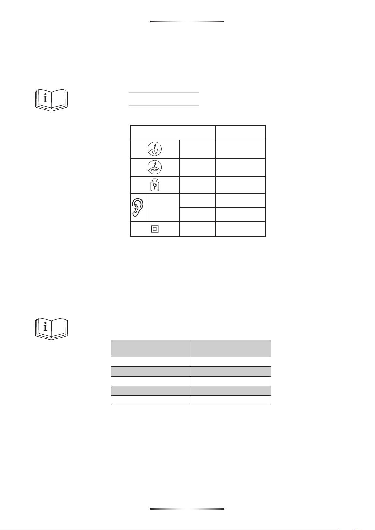
Consulte los límites de tamaño de pieza en el apartado
i2 (pág. 4).
2. Desembalado y ensamblado
Desembalado
1. Abrir la caja cortando el precinto.
2. Retirar los topes de cartón superiores.
3. Extraer la máquina de la caja, sujetando rmemente la
cabeza operadora y el cuerpo del motor, utilizando ambas
manos para equilibrar el peso.
4. Extraer la caja de accesorios.
5. Extraer la documentación.
6. Conservar permanentemente la caja de cartón, sus
topes, la caja de accesorios y la documentación en un
ambiente seguro, inventariado, de fácil acceso y conocido
por el operador de la máquina.
Embalado
Operación 1: Asegurar, plegar y jar la cabeza opera-
dora, para ello:
1. Poner el cabezal superior a 0º horizontales.
2. Poner el cabezal superior a 90º verticales.
3. Colocar el protector de forma que haga contacto en la
mesa de corte.
4. Bajar el cabezal a tope, presentándolo y bloquearlo.
Operación 2: Embalar la máquina.
1. Localizar la caja de cartón y sus rellenos de embalaje.
2. Localizar la documentación.
3. Sujetar rmemente la máquina por la cabeza operado-
ra y el cuerpo del motor.
4. Depositar la maquina sobre las hendiduras del relleno
de embalaje.
5. Depositar la documentación de la máquina.
6. Colocar los rellenos de embalaje.
Cerrar la caja jándola con precinto.
3. Establecimiento o jación de la
herramienta en una posición estable
1. Obligatoriamente el puesto de trabajo en el que se im-
planta la máquina debe ser seguro.
2. Apoyar la herramienta en posición estable sobre una
supercie plana.
3. La base de la ingleteadora dispone de los cuatro ori-
cios jar sólidamente la máquina al banco de trabajo. Se
recomienda jar la máquina al banco mediante los corres-
pondientes tornillos y tuercas.
4. Conexión a la alimentación, cableado,
fusibles, tipo de base para la clavija y
requisitos para la toma de tierra
1. Para alimentar la máquina conectar la clavija schuko a
una toma reglamentaria capaz de suministrar como míni-
mo 2500VA.
2. La máquina tiene su cableado interno completamente
terminado por lo que no necesita cableado alguno de ins-
talación.
3. La máquina no lleva fusibles, aunque se recomienda
el uso de un interruptor magnetotérmico dedicado como
protección de la máquina.
4. La máquina dispone de un equipo eléctrico de cate-
goría I, por lo que no hace uso de la toma de tierra de la
instalación eléctrica.
5. Sólo conecte la máquina en una intalación certicada y
hecha por un instalador autorizado.
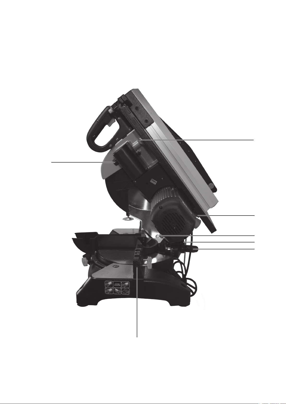
5. Descripción ilustrada de las funciones
1. Palanca selectora de ángulo de mesa inferior.
2. Bloqueo del cabezal de corte.
3. Bloqueo mesa inferior.
4. Pomo de bloqueo del cabezal abajo.
5. Ajuste de límite de bajada de disco.
6. Inserción de soporte de corte largo.
7. Inserción de mordazas.
8. Pomo selector de inclinación del cabezal.
9. Bloqueo pulsador puesta en marcha.
10a. Bloqueo mesa superior.
10b. Bloqueo mesa superior.
11. Regulador altura mesa superior.
6. Limitaciones sobre las condiciones
ambientales
El grado IP de esta máquina eléctrica es 20. Esta máquina
esta protegida contra acceso a partes peligrosas con un
dedo y contra los cuerpos sólidos extraños de 12’5 mm de
diámetro y mayores. Esta máquina eléctrica no tiene nin-
guna clase de protección contra la penetración del agua
por lo que se prohíbe su uso en condiciones ambientales
exteriores o interiores con riesgo de precipitación.