stayer TV509 User manual

www.grupostayer.com
Manual de instrucciones
ES
Área Empresarial Andalucía - Sector I
Calle Sierra de Cazorla nº7
C.P: 28320 Pinto (Madrid) SPAIN
Email: sales@grupostayer.com
Email: info@grupostayer.com
Istruzioni d’uso
IT
Operating instructions
GB
Bedienungsanleitung
DE
Instructions d’emploi
FR
Manual de instruções
P
Kullanma Kılavuzu
TR
TV509
TV509B
TV509C

3
1
3
4
5
6
7
10
9
8
13
11
12
12
16
17
18
20
19
26
11
15
25
14
17
27
28
2
2
9
4
A

4
B1
26 B2
27
28
C
D13

E
G
H
2
F

6.1.
TV 509
TV 509 B
TV 509 C
W
2400
2400
2500
-1
min
3800
3800
3800
mm
Ø 355 x 3 x 25,4
Ø 355 x 3 x 25,4
Ø 355 x 3 x 25,4
IP
II
II
II
kg
18.2
18
19
L dB(A)
pA
95
97
94
L dB(A)
WA
103
108
107
2
a m/s
h
3
3
4.38
rpm
K=3 dB
2
K=1.5 m/s
kg
Ø
Ø

6.2 Dichiarazione di conformità CE
Il sottoscritto: STAYER IBERICA, S.A.
Con indirizzo a:
Calle Sierra de Cazorla, 7
Área Empresarial Andalucía - Sector 1
28320 PINTO (MADRID)
Tel.: +34 902 91 86 81 / Fax: +34 91 691 91 72
CERTIFICA
Che la macchina:
Tipo : TRONCATRICE
Modellos: TV509 / TV509B / TV509C
Noi dichiariamo sotto la nostra unica e sola responsabilità
che questo prodotto si trova in conformità con le norme o i
documenti normalizzati seguenti:
EN 61029-1, EN 61029-2-10, EN 55014-1, EN 55014-2, EN
61000-3-2, EN 61000-3-3 in conformità con i regolamenti
2006/42/CE, 2011/65/EU, 2014/30/EU.
ITALIANO
6
6
Ramiro de la Fuente
Direttore generale
Gennaio 2017

Only approaching the cutting disc running against the
workpiece when the disc reaches its maximum speed.
After starting wait at least 4 seconds until the disk rotate at
rated speed.
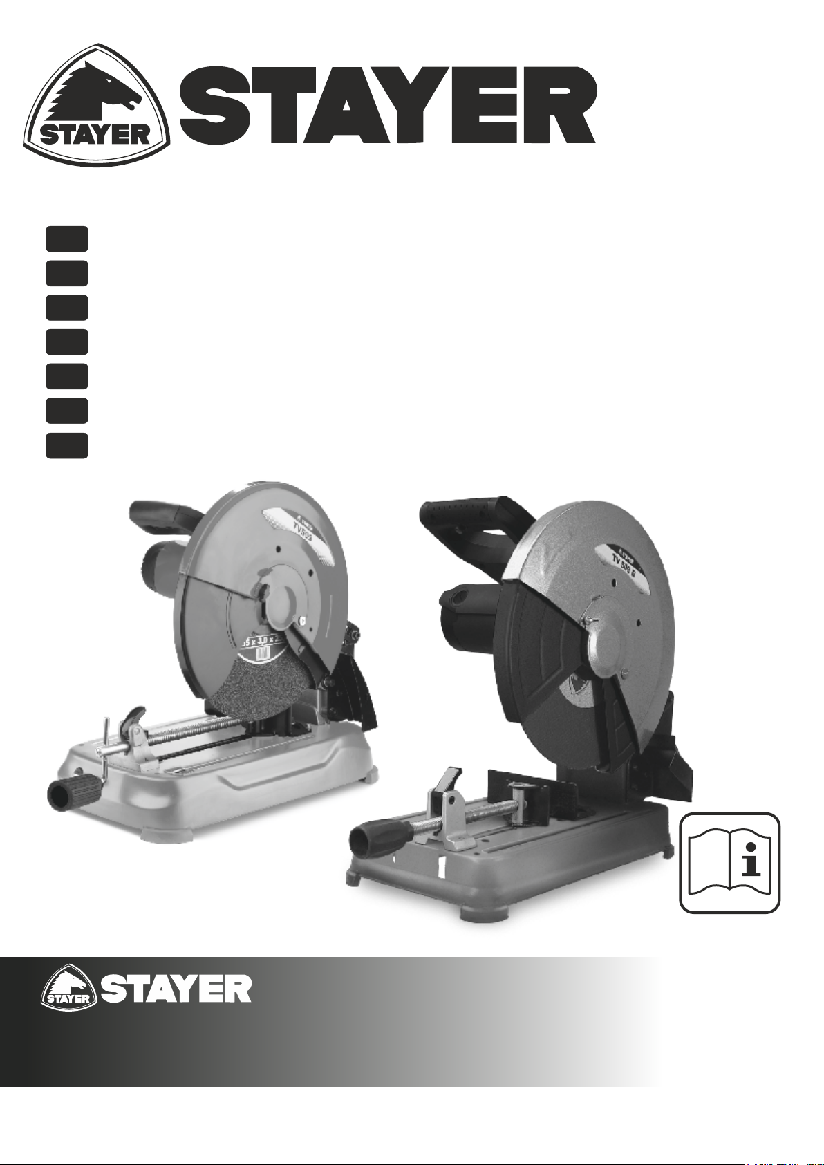
Always firmly clamp the workpiece. Do not cut
workpieces that are too small to clamp. Otherwise, the
clearance of your hand to the rotating cutting disc is too
small.
If the cutting disc becomes jammed, switch the
machine off and wait until the cutting disc comes to a
complete stop. Never attempt to remove a still running
cutting disc from the cut, otherwise there is danger of
kickback. Determine and correct the cause for the
jamming.
After switching off, do not stop the cutting disc by
applying lateral pressure to it. The cutting disc can
become damaged, break or lead to kickback.
Do not force the cutting disc into the workpiece and do
not apply too much pressure when using the power
tool. Particularly avoid jamming or wedging the cutting
disc when working corners or sharp edges. When the
cutting disc is damaged due to abuse, cracks can form that
can lead to breakage without prior warning.
Wear a work apron. Pay attention that other persons are
not put at risk from sparking. Remove flammable
materials in close vicinity. Sparking occurs when cutting
metal.
Use the cut off grinder only for cutting materials
mentioned under “Intended Use”. Otherwise, the cut off
grinder can be subject to overload.
Do not use damaged, out-of-centre or vibrating cutting
discs. Damaged cutting discs cause increased friction,
binding of the cutting disc and kickback.
Always use cutting discs with correct size and shape
(diamond versus round) of arbor holes. Cutting discs
that do not match the mounting hardware of the cut off
grinder will run eccentrically, causing loss of control.
Do not attach a saw chain woodcarving blade or
toothed saw blade. Such blades create frequent kickback
and loss of control over the power tool.
Observe the operating instructions of the cut-off wheel
manufacturer for assembly and use of the cut-off
wheel. Cut-off wheels that do not fit can lead to injury as well
as to jamming, breaking or kickback.
Do not use accessories which are not specifically
designed and recommended by the tool manufacturer.
Just because the accessory can be attached to your power
tool, it does not assure safe operation.
Do not touch the cutting disc after working before it has
cooled. The cutting disc becomes very hot while working.
The machine TV509 / TV509B / TV509C is intended for stationary
use with cutting abrasive discs to perform lengthways and
crossways straight cuts or mitre cuts to 45° in metal materials
without the use of water.
This manual is consistent with the date of manufacture of your
machine, you will find information on the technical data of the
machine acquired manual check for updates of our machines on
the website: www.grupostayer.com
1. Contents page
2.Specific safety instructions......................................20
3.Instructions for use....................................................21
3.1 Placement Tool.............................................................21
3.2 Assembly......................................................................21
3.3 Illustrated description............................................21
4.Operating instructions..............................................21
4.1 Placement and testing..........................................21
4.2 Tool change..........................................................22
4.3 Operation adjustment...........................................23
4.4 Limitations on the size of the workpiece.................23
4.5 General instructions for use..................................24
5.Maintenance and service instructions.....................24
5.1 Cleaning...............................................................24
6.2 Repair service.......................................................24
5.3 Warranty...............................................................24
5.4 Disposal and recycling..........................................24
6.Regulations................................................................24
6.1 Technical Data......................................................24
6.2 EU declaration of conformity.................................25
2. Specific safety instructions
Never stand on the power tool. Serious injuries could
occur when the power tool tips over or when accidentally
coming into contact with the cutting disc.
Always use the blade guard. A blade guard protects the
user against broken off parts of the cutting disc and against
accidental touching of the cutting disc.
Make sure that the guard operates properly and that it
can move freely. Never lock the guard in place when
opened.
Use the power tool only for dry cutting. Water
penetrating into a power tool increases the risk of an electric
shock.
Keep the mains cable away from rotating application
tools. The mains cable can be cut through or get caught.
Keep handles dry, clean, and free from oil and grease.
Greasy, oily handles are slippery causing loss of control.
Never remove cutting remainders, metal chips, etc.
from the cutting area while the machine is running.
Always guide the tool arm back to the neutral position first
and then switch the machine off.
Guide the cutting disc against the workpiece only when
the machine is switched on. Otherwise, there is danger of
kickback, when the cutting disc becomes wedged in the
workpiece.
ENGLISH
7
7

Check the cable regularly and have a damaged cable
repaired only through an authorised customer service
agent for STAYER power tools. Replace damaged
extension cables. This will ensure that the safety of the
power tool is maintained.
Store the machine in a safe manner when not being
used. The storage location must be dry and lockable.
This prevents the machine from storage damage, and from
being operated by untrained persons.
Secure the workpiece. A workpiece clamped with
clamping devices or in a vice is held more secure than by
hand.
Never leave the machine before it has come to a
complete stop. Cutting tools that are still running can
cause injuries.
Never use the machine with a damaged cable. Do not
touch the damaged cable and pull the mains plug when
the cable is damaged while working. Damaged cables
increase the risk of an electric shock.
Keep hands away from the cutting area while
the machine is running. Danger of injury when
coming into contact with the cutting disc.
Wear ear protectors. Exposure to noise can cause
hearing loss.
Wear safety goggles.
Wear a dust respirator.
Wear protective gloves.
3.Instructions for use
3.1 Placement Tool
Read all safety warnings and all instructions.
Failure to follow the warnings and instructions may
result in electric shock, fire and/or serious injury.
3.2 Assembly
Avoid unintentional starting of the machine.
During assembly and for all work on the machine,
the power plug must not be connected to the
mains supply.
Carefully remove all parts included in the delivery from their
packaging. Remove all packaging material from the
machine and the accessories provided.
Before starting the operation of the machine for the first
time, check if all parts listed below have been supplied:
– Cut-off grinder with mounted cutting disc
– Ring spanner
Check the power tool for possible damage.
Before further use of the machine, check that all
protective devices are fully functional.
ENGLISH
8
8
Any lightly damaged parts must be carefully checked to
ensure flawless operation of the tool. All parts must be
properly mounted and all conditions fulfilled that ensure
faultless operation.
Damaged protective devices and parts must be
immediately replaced by an authorised service centre.
Stationary or Flexible Mounting
To ensure safe handling, the machine must be mounted on
a level and stable surface (e. g., workbench) prior to using.
Stationary mounting (see figure A)
– Fasten the power tool with suitable screw fasteners to the
working surface. The mounting holes 11 serve for this
purpose.
Flexible Mounting (not recommended!)
In the exceptional case that it should not be possible to
firmly bench-mount the power tool, you can provisionally
place the legs of base plate 12 on a suitable surface (e. g. a
workbench, level floor, etc.) without bolting the machine
down.
3.3 Illustrated description
1 Lock-off button for On/Off switch
2 On/Off switch
3 Handle
4 Retracting blade guard
5 Spindle lock
6 Cutting disc
7 Top of workpiece support
8 Clamping spindle
9 Quick-release button
10 Spindle handle
11 Mounting holes
12 Based machine bed
13 Locking screw for angle stop
14 Ring spanner (15 mm; 13 mm)*
15 Transport safety-lock*
16 Depth stop cutting
17 Tool arm
18 Transport handle
19 Carter disk
20 Spark guard
21 Tool spindle
22 Clamping flange
23 Washer
24 Bolt
25 Lock nut of the depth stop
26 Arrow disc guide
27 Thumbscrew
28 Protective Cover Flangia
*Accessories shown or described are not part of the standard
delivery scope of the product. A complete overview of accessories
can be found in our accessories program.
4. Operating instructions
4.1 Placement and testing
Observe correct mains voltage! The voltage of the

4.2 Tool change
Before any work on the machine itself, pull the mains
plug.
Actuate the spindle lock 5 only when the tool spindle 21
is stopped. Otherwise, the machine can become
damaged.
Do not touch the cutting disc 6 after working before it
has cooled. The cutting disc 6 becomes very hot while
working.
Use only cutting discs 6 that have an equal or higher
maximal allowable speed than the noload speed of your
power tool.
Use only cutting discs 6 that correspond to the
characteristic data given in these operating instructions and
are checked according to EN 12413 and marked
appropriately.
Place unused cutting discs 6 in an enclosed container or in
the original packaging. Store cutting discs 6 lying flat.
Removing the Cutting Disc (Fig. B1 - B2)
– Bring the power tool into the working position.
– Loosen the thumbscrew, to move the cap.
– Swing back the retracting blade guard 4 to the stop.
– Turn hexagon bolt 24 with the provided ring spanner 14
and at the same time press the spindle lock 5 until it
engages.
Advice. Alternatively lock the spindle 5, with a piece of
wood at the angle stop 7 and lock the disc 6, to proceed to
remove the disc.
– Hold the spindle lock pressed 5 and unscrew the
hexagon bolt 24.
– Remove the washer 23 and the clamping flange 22.
– Remove the cutting disc 6.
Installing the Cutting Disc
If required, clean all parts to be mounted prior to assembly.
– Mount the cutting disc on the spindle 6 new tool holder 21
making sure that the direction of the disk according to
arrow 26.
– Mount the clamping flange 22, the washer 23 and the
hexagon bolt 24.
Press spindle lock 5 until it engages and tighten hexagon
bolt 24 with the provided ring spanner.
– Slowly guide the retracting blade guard 4 down until the
cutting disc 6 is covered off.
– Make sure that the retracting blade guard 4 operates
properly.
– Place the protective cap Flangia 28 and tighten the
thumbscrew 27.
After mounting the cutting disc 6 and before switching on,
check whether the cutting disc is properly mounted and if it
can rotate freely. Get oriented by the arrow 26.
– Make sure that the cutting disc 6 does not graze against
the retracting blade guard 4, the blade guard 19 or against
other parts.
power source must agree with the voltage specified on
the nameplate of the machine. Power tools marked
with 230 V can also be operated with 220 V.
Check the cutting disc 6 before using. The cutting disc
must be properly mounted and must rotate freely.
Carry out a 30 second (min.) test run with no load. Do
not use damaged, out-of-centre or vibrating cutting
discs. Damaged cutting discs 6 can burst and cause
injuries.
Dusts from materials such lead-containing coatings,
minerals and metal can be harmful to one’s health. Contact
with or inhaling the dusts can trigger allergic reactions to the
operator or bystanders and/or lead to respiratory infections.
Certain metal dusts are considered hazardous, especially
in conjunction with alloys such as zinc, aluminium or
chromium. Materials containing asbestos may only be
worked by specialists.
– Provide for good ventilation of the working place.
– It is recommended to wear a P2 filter-class respirator.
Observe the relevant regulations in your country for the
materials to be worked.
The blade 6 can be blocked by dust, chips or workpiece
fragments in the slot of the bed 12.
– Switch the machine off and pull the mains plug from the
socket outlet.
– Wait until the cutting disc 6 has come to a complete stop.
– Tilt the machine toward the rear, so that small workpiece
fragments can fall out of the opening intended for this
purpose.
If required, use a suitable tool to remove all workpiece
fragments.
Prevent dust accumulation at the workplace.
Dusts can easily ignite.
Position of the Operator (see figure F)
Do not stand in a line with the cutting disc 6 in front of
the machine. Always stand aside of the cutting disc .
This measure provides for better protection of your body
against possible splinters in case of cutting disc breakage.
Switching On and Off (see figure G)
To start the machine, firstly press the lockoff button 1. Then
press the On/Off switch 2 and keep it pressed.
For safety reasons, the On/Off switch 2 cannot be
locked; it must remain pressed during the entire
operation.
To switch off the machine, release the On/Off switch 2.
Soft starting
The electronic soft starting feature limits the torque upon
switching on and increases the working life of the motor.
ENGLISH
9
9

Loosening the Workpiece
– Loosen the spindle handle 10.
– Tilt up the quick release 9 and pull the clamping spindle 8
away from the workpiece.
Adjusting the Depth Stop (see figure H)
In the delivery condition of the machine, the depth stop 16 is
adjusted in such a manner that a new 355 mm cutting disc 6
does not touch the base plate 12 when cutting.
To compensate the wear of the cutting disc 6, the depth stop
16 can be set deeper.
When using a new cutting disc 6, the depth stop 16 must
then always be set back to the original position.
Always adjust the depth stop 16 in such a manner
that the cutting disc 6 does not touch the base plate
12 when cutting.
– Bring the power tool into the working position. (see
“Releasing the Machine (Working Position)”)
– Loosen lock nut 25 with the spanner.
– Swing the tool arm with the handle 3 to the requested
position.
– Screw the depth stop 16 in clockwise or anticlockwise
direction until the screw head touches the housing.
– Slowly guide the tool arm upward and tighten the lock nut
25.
Cutting capacity, max. (0°/0°): 140 mm
Cutting Metal
– Set the desired mitre angle.
– Firmly clamp the workpiece as appropriate for its
dimensions.
– Switch on the machine.
– Slowly guide the tool arm downward with the handle 3.
– Cut the workpiece applying uniform feed.
– Switch the machine off and wait until the cutting disc
comes to a complete stop.
– Guide the tool arm slowly upward.
4.4 Limitations on the size of the workpiece
Permissible Workpiece Dimensions
Maximal workpiece sizes:
Minimal workpiece sizes (= all workpieces that can be clamped
via the clamping spindle 8): Length 80 mm
– Run the machine for approx. 60 seconds.
Should significant vibrations occur, switch off the machine
immediately; remove and install the cutting disc 6 again.
4.3 Operation adjustment.
Before any work on the machine itself, pull the
mains plug.
Transport Safety (see figure C)
The transport safety-lock 15 enables easier handling of the
machine when transporting to various working locations.
Releasing the Machine (Working Position)
– Push the tool arm by the handle 3 down a little in order to
relieve the transport safetylock 15.
– Pull the transport safety-lock 15 completely outward.
– Guide the tool arm slowly upward.
When working, pay attention that the transport
safety-lock is not pushed inwards. Otherwise, the
tool arm cannot be lowered to the requested depth.
Securing the Machine (Transport Position)
– Guide the tool arm 17 downward until the transport safety-
lock 15 can be pushed completely inward 16.
Transport
– Always carry the power tool by its transport handle 18.
When transporting the power tool, use only the
transport devices and never use the protective
devices.
Adjusting the Cutting Angle (see figure D)
The miter angle can be set in a range from -15° to +45°.
Frequently used mitre angles are identified on the angle
stop 7 with appropriate markings. The -15° and 45° position
are set at the respective end stop.
– Loosen the locking screws 13 for the angle stop with the
supplied ring spanner 14.
– Adjust the desired angle and firmly tighten both locking
screws 13 again.
Displacing the Angle Stop (see figure D)
When cutting workpieces wider than 130 mm, the angle
stop 7 can be displaced to the rear.
– Completely unscrew locking screws 13 with the supplied
ring spanner 14.
– Move the angle stop 7 toward the rear by one or two holes
to the desired clearance.
– Adjust the desired angle and firmly tighten both locking
screws 13 again.
Clamping the Workpiece (see figure E)
To ensure optimum working safety, the workpiece must
always be firmly clamped.
Do not saw workpieces that are too small to clamp.
Long workpieces must be underlaid or supported at their
free end.
– To first approximation the fast thread 9 lift and push the
spindle. Lower 9 for tightening
– Place the workpiece against the angle stop 7.
– Slide the clamping spindle 8 against the workpiece and
firmly clamp the workpiece with the spindle handle 10.
ENGLISH
10
10
Dimensions of suitable cutting discs
Cutting disc diameter, max.
Cutting discs width, max.
Mounting hole diameter
mm
mm
mm
355
3
25,4
Mitre/Bevel Angle
Workpiece Form 0º 45º 0º 45º
0º
45º
140 Ø 110 Ø
100 x 100
105 x 85
130 x 130
254 x 73
TV509 TV509C
120 Ø 80 Ø
50 x 50
80 x 50
105 x 105
130 x 90
130 Ø 90 Ø
80 x 80
85 x 70
120 x 120
210 x 60
TV509B
Mitre/Bevel Angle Mitre/Bevel Angle

5.3 Warranty
Warranty card
Included in the documentation that accompanies this
equipment, you should find the warranty card. You should
fill out the card completely and return to vendor with a copy
of purchasing receipt or invoice and you should receive a
receipt.
Note: If you cannot find the warranty card within the
documentation, you must ask for it through your supplier.
The warranty is limited only to manufacturing defects and
expire if pieces have been removed or manipulated or
repaired other than the manufacturer.
5.4 Disposal and recycling
The machine, accessories and packaging should be sorted
for environmental-friendly recycling.
Only for EC countries:
Do not dispose of power tools into household waste!
According the European Guideline 2002/96/EC
for Waste Electrical and Electronic Equipment
and its implementation into national right, power
tools that are no longer usable must be
collected separately and disposed of in an
environmentally correct manner.
Subject to change without notice.
6. Regulations
6.1 Technical Data
= Power input
= No load speed
= Disc dimension
Ins = Protection class
= Weigth
L = Sound power level
WA
A
L = Sound pressure level
P
= Vibration
The values given are valid for nominal voltages [U] 230/240 V ~
50/60 Hz - 110/120 V ~ 60Hz. For lower voltage and models for
specific countries, these values can vary. Please observe the
article number on the type plate of your machine. The trade
names of the individual machines may vary.
Noise/Vibration Information
Measured sound values determined according to EN 61029.
Typically the A-weighted noise levels of the product are:
Sound pressure level 97 dB(A); Sound power level 108 dB(A).
Uncertainty K=3 dB.
Wear hearing protection!
4.5 General instructions for use
Cutting Operation
- Wait for the drive to reach its maximum speed (about
4 sec)
Do not touch the cutting disc 6 after working before it
has cooled. The cutting disc becomes very hot while
working.
Make sure that the spark guard 20 is properly mounted.
Sparking occurs when cutting metal.
Protect the cutting disc 6 against impact, shock and grease.
Do not subject the cutting disc 6 to lateral pressure.
Do not strain the power tool so heavily that it comes to a
standstill.
Excessive feed considerably reduces the performance
capability of the machine and shortens the service life of the
cutting disc.
Use only cutting discs that are suitable for the material to be
worked.
5. Maintenance and service instructions
5.1 Cleaning
Before any work on the machine itself, pull the mains
plug.
Clean the ventilation slots of your power tool regularly
with a soft brush. The motor fan draws dust into the
housing, and a large accumulation of metal dust can lead to
electrical hazards.
In extreme conditions, always use dust extraction as
far as possible. Blow out ventilation slots frequently
and install a residual current device (RCD). When
working metals, conductive dust can settle in the interior of
the power tool. The total insulation of the power tool can be
impaired.
Have maintenance and repair work performed only by
qualified specialists. In this manner, it can be ensured that
the safety of the power tool is maintained.
The retracting blade guard must always be able to move
freely and retract automatically. Therefore, always keep the
area around the retracting blade guard clean.
If the machine should fail despite the care taken in
manufacturing and testing procedures, repair should be
carried out by an after-sales service centre for STAYER
power tools.
5.2 Repair service
Our after-sales service responds to your questions
concerning maintenance and repair of your product as well
as spare parts. Exploded views and information on spare
parts can also be found under:
info@grupostayer.com
Our customer consultants answer your questions
concerning best buy, application and adjustment of
products and accessories.
ENGLISH
11
11
rpm
Ø
Ø

Vibration total values (triax vector sum) determined according to
EN 61029: 2 2
Vibration emission value a = 3.0m/s , Uncertainty K =1.5 m/s .
h
The vibration emission level given in this information sheet has
been measured in accordance with a standardised test given in
EN 61029 and may be used to compare one tool with another. It
may be used for a preliminary assessment of exposure.
The declared vibration emission level represents the main
applications of the tool. However if the tool is used for different
applications, with different accessories or poorly maintained, the
vibration emission may differ. This may significantly increase the
exposure level over the total working period.
An estimation of the level of exposure to vibration should also take
into account the times when the tool is switched off or when it is
running but not actually doing the job. This may significantly
reduce the exposure level over the total working period.
Identify additional safety measures to protect the operator from
the effects of vibration such as: maintain the tool and the
accessories, keep the hands warm, organisation of work patterns.
6.2 EU declaration of conformity
The undersigned: STAYER IBERICA, S.A.
With address at:
Calle Sierra de Cazorla, 7
Área Empresarial Andalucía - Sector 1
28320 PINTO (MADRID)
Tel.: +34 902 91 86 81 / Fax: +34 91 691 91 72
CERTIFIES
That the machine:
Type: CUT´OFF AND MITRE SAW
Models: TV509 / TV509B / TV509C
We declare under our sole responsibility that this product is
in conformity with the following standards or standardized
documents: EN 61029-1, EN 61029-2-10, EN 55014-1, EN
55014-2, EN 61000-3-2, EN 61000-3-3 according to EU
Regulations 2006/42/CE, 2011/65/EU, 2014/30/EU.
ENGLISH
12
12
Ramiro de la Fuente
Managing Director
January, 2017

www.grupostayer.com
Área Empresarial Andalucía - Sector I
Calle Sierra de Cazorla nº7
C.P: 28320 Pinto (Madrid) SPAIN
Email: sales@grupostayer.com
Email: info@grupostayer.com
This manual suits for next models
2
Table of contents
Other stayer Saw manuals

stayer
stayer SC250IW User manual

stayer
stayer TV509D User manual

stayer
stayer SC210W User manual

stayer
stayer CP L20 User manual

stayer
stayer CP L20 User manual

stayer
stayer SC210BW User manual

stayer
stayer SN1435B User manual

stayer
stayer TV509D User manual

stayer
stayer SC241W User manual

stayer
stayer CP L18 User manual

stayer
stayer SC2600W User manual

stayer
stayer SS280P User manual

stayer
stayer CP190B User manual

stayer
stayer CP190 User manual

stayer
stayer CM230K User manual

stayer
stayer SCR 255 CW User manual

stayer
stayer SCR216W User manual

stayer
stayer SCR315W User manual

stayer
stayer SC300W User manual

stayer
stayer CP L18 User manual