STI ValuScan VS6500 Series User manual

ValuScan VS6500 Series with C & D Controllers
Rev.A
1
Table of Contents
Section 1 – Introduction.................................................... 3
Section 2 – Installation ...................................................... 3
Section 3 – Introduction to Setup Software ................... 6
Section 4 – Windows Setup Software ............................. 7
Section 5 – General Setup Commands ........................... 8
Section 6 – Relay Output .................................................. 9
Section 7 – Serial Port Connections and Setup ........... 10
Section 8 – Serial Output Report Commands ............. 11
Section 9 – Serial Timing Commands .......................... 17
Section 10 – Array Modifying Commands .................. 18
Section 11 – Troubleshooting ........................................ 19
Section 12 – Specifications ............................................. 21
Section 13 – ASCII Terminal Emulators ...................... 22
Section 14 – Spare Parts .................................................. 22
Section 15 – Dimensional Drawings ............................. 23
Section 16 – Warranty ..................................................... 27

SCIENTIFIC TECHNOLOGIES INC.
R
2
This page is intentionally left blank.

ValuScan VS6500 Series with C & D Controllers
Rev.A
3
12
Installation
Introduction
!
Warning! STI scanners are not designed for
and must not be used for personnel protection
(safety) applications. STI has a wide range of safety
products for these applications. Contact STI for
information on our safety products.
Thank you for purchasing a ValuScan. This
manual covers scanners using this Serial
Controllers Series C and D. A separate manual
covers the VSU controllers Series A and B.
These items are included with the scanner.
■
■■Transmitter
■
■■Receiver
■
■■Controller
■
■■Transmitter cable
■
■■Receiver cable
■
■■Documentation kit (optional)
You will need an IBM compatible PC for
software setup of the scanner.
!
Warning! Installation and maintenance must
be performed by qualified personnel.
C
ONTROLLER
A
DJUSTMENTS
1.
!
Warning! Set JMP 10 to AMP for 0.25
and M5 Series transmitters and receivers.
Failure to do so may damage your scanner. For
M10, 0.50, 0.75, and 1.50 Series transmitters and
receivers set to Volt for best performance.
2. Set JMP 3 to 50.
3. Set JMP 1 to HI.
4. Set JMP 2 to STD for 0.25, M5, and M10
Series. Set to LR for 0.50, 0.75, and 1.50 Series.
5. Set JMP 9 to Run.
6. Rotate Pot 1 clockwise 25 turns.
7. Set S1 position 2 (labelled A) on; set all
other positions off.
8. Verify the fuse is correctly rated for
your operating voltage.
Figure 2.1 Location of settings
1
3
4
2
5
6
7
8
9

SCIENTIFIC TECHNOLOGIES INC.
R
4
– For 115 VAC use a 250 mA, 250 V
time lag (slow blow) fuse;
– For 230 VAC use a 125 mA, 250 V
time lag (slow blow) fuse;
– For 24 VDC use a 2 A, 250 V time lag
(slow blow) fuse.
9. For AC powered units, select the
appropriate operating voltage.
M
OUNTING
THE
T
RANSMITTER
AND
R
ECEIVER
Mount the transmitter and receiver parallel
to each other, with no offset, and with their
connectors pointing in the same direction.
Mount the transmitter above the receiver in
horizontal installations. See Section 16 for
mounting dimensions.
Use 10-32 or M5 hardware for M5, 0.25, and
M10 series. Use 1/4 in. or M6 hardware for 0.50,
0.75, and 1.50 series.
M
OUNTING
THE
C
ONTROLLER
For Series C controller with enclosure use
1/4 inch or M6 hardware.
Series D controller without enclosure must
be installed within a metal protective enclosure
to assure conformity with Electromagnetic
Compatibility Directive 89/336/EEC and 92/
31/EEC. Use 6-32 or M3.5 hardware.
P
OWER
AND
G
ROUND
/E
ARTH
C
ONNECTIONS
For AC Powered Systems, connect ground
(earth), neutral, and line (figure 2.2).
If the system is permanently wired install a
switch near the controller to disconnect the
scanner when needed.
If the system is line cord powered use a
non-locking plug that mates with your power
outlet. European installations require a
harmonized line cord marked HAR. Minimum
conductor size is 18 AWG (0.823 mm2).
Section 2 – Installation
For DC powered systems, connect ground
(earth), –DC, and +DC (figure 2.2). Install a
switch near the controller to disconnect power
when needed.
T
RANSMITTER
AND
R
ECEIVER
C
ABLES
Attach the transmitter cable to the
transmitter and the controller as shown in
figure 2.3.
A
LIGNMENT
Apply power to the scanner. Refer to figure
2.3 for location of components.
1. Align the transmitter and receiver until
the green LED on the controller board marked
“CLR” is on. This LED is duplicated on the
transmitter.
Power and Ground/Earth
Figure 2.2 Power and ground/earth connections

ValuScan VS6500 Series with C & D Controllers
Rev.A
5
2. Rotate POT 1 counterclockwise until the
green LED just turns off and the red LED
marked “BLOCK” turns on. This LED is
duplicated on the transmitter.
3. Realign the transmitter and receiver until
the green LED is on.
Repeat steps 2 and 3 until the green LED
will no longer turn on. Finally, rotate POT 1
clockwise one full revolution past the point
when the green LED turns on. Tighten all
mounting hardware.
For 0.50, 0.75, and 1.50 series only, in
applications where high optical contamination
is anticipated, set POT 1 fully clockwise.
Section 2 – Installation
Figure 2.3 Transmitter & receiver connectors, indicator
LEDs and range potentiometer (POT 1).
Transmitter
Connector
Receiver
Connector
Pot 1
Indicator
LEDs

SCIENTIFIC TECHNOLOGIES INC.
R
6
STI provides 2 diskettes with the scanner
documentation kit. Both DOS and Windows
Setup software applications are included on the
diskettes. This section provides information on
the DOS software which is also applicable to the
terminal window under the Windows software.
S
TARTUP
P
ARAMETERS
2. Turn on the scanner and your computer.
3. Run the STI setup program FVS.EXE
found on the diskette provided. The software
starts in a graphic display mode. Switch to the
terminal mode of the setup program by
pressing Alt-W. Press ESC twice and Enter.
4. Type the setup commands needed. Refer
to the individual output sections for the
commands needed for the output you are
using.
• Use upper or lower case characters.
• Press ENTER after each command.
• Type spaces as shown.
• “ ” means the scanner recognized your
command. Continue with set-up.
• “!” means the scanner did not recognize
your command. Check your syntax and re-enter
the command.
• If your screen does not display the
commands you type, the scanner is in the serial
reporting mode. Press ESC twice and Enter.
5. Save your settings.
After entering the commands and verifying
proper scanner operation, type the command
SAVE to the scanner.
6. Set positions 2, 3, and 4 of the output
mode switch to off and reset the scanner.
7. Exit the setup program by pressing Alt-X.
Turn off power to the scanner and the personal
computer. Disconnect the scanner from the
computer’s serial port.
IMPORTANT
You must save your software settings! They
shall be erased unless you save them.
Set the output mode switch to use your settings!
Entering the graphic display mode erases some
settings! This occurs when you start the setup
program or when you toggle from the terminal
mode. You can recover your settings if you have
saved them by pressing the reset switch.
3
DOS Setup Software
Figure 3.1 Reset and output mode switches
The scanner uses factory default parameters
or parameters you set and save. Resetting the
scanner loads parameters selected by positions
A, B, and C of the output mode switch (figure
3.1). The scanner resets when the reset switch is
pressed or when power is applied.
Position Start-up
A B C Mode
On Off Off Factory default settings
On On Off Alternate Default settings
Off Off Off User saved settings
If the factory default settings are not suited
to your application, set your own parameters
and save them. Follow these steps.
1. Connect the scanner to the COM1 serial
port on your personal computer.
Output
Mode

ValuScan VS6500 Series with C & D Controllers
Rev.A
7
4
Windows Setup Software
Only specific versions of the firmware allow
setup using the Windows software selection
boxes. Versions other than these must use the
DOS software or the terminal window in the
Windows Software. For A/B controllers the
firmware for use with Window Software is
firmware number 1. For R & S controllers, the
firmware is number 6.
To install the Windows software follow
these steps.
1. Insert diskette 1 into your floppy drive.
These instructions assume this is drive A:\. If
you are using a different drive, modify these
instructions to use the appropriate drive name.
2. Click the START button and select RUN.
3. Type A:\SETUP.EXE in the command
box and click OK.
4. Remove Diskette 1 and insert diskette 2
when requrested.
To run the software after installation, click
on the START button, select PROGRAMS then
VALUSCAN SETUP.
Note that while you can run the software
without have a scanner connected to your PC,
you cannot actually send commands and errors
will result if you attempt to do so.
The first dialog box to appear when
running the Windows software asks which
controller is being used. Select “AB” for the
VSU Series A or Series B controller, and for the
Series R or Series S controller. Select “CD” for
the Serial Controllers, Series C or D.
Use of the Windows software is intuitive to
anyone used to Windows based applications.
The HELP function is extensive, and under
Contents, you will find an overview of the
program as well as a slightly condensed version
of this manual.
Generally, you make your operating
parameter selections using click-off boxes.
Certain newer commands and infrequently
used commands are not available through the
menus. Refer to the paragraphs below marked
“Terminal Window” on how to make and save
changes if you need to use these commands.
After you make all your changes, you must
perform the following steps to save your
settings.
1. Click the START SCANNER button on
the main window page.
2. Click the STOP SCANNER button on the
main window page.
3. Click the SAVE SETTINGS TO
SCANNER button on the main window page.
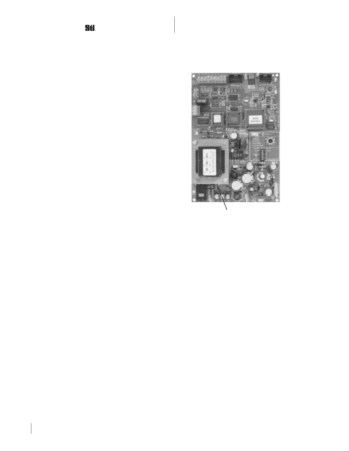
4. Set the output mode switch to use your
settings. See figure 3.1.
IMPORTANT
You must save your software setings. They shall
be erased in the scanner unless they are saved. After
saving your settings, you must set the output mode
switch to use these settings or factory default settings
will be used.
T
ERMINAL
W
INDOW
The Windows software includes a window
for direct terminal communication with the
scanner. This is useful for debugging and to
implement commands not on the Windows
click-off boxes. To access this window select the
Terminal menu. You may need to select the
“add linefeed” box depending upon your
computer. After selecting this box, point your
mouse cursor in the box and click once. You can
then type commands in the box. The commands
are given under the various output sections of

SCIENTIFIC TECHNOLOGIES INC.
R
8
The following commands are useful during
setup.
HELP? shows a short listing of most
commands.
WHAT? lists the current status of most
parameters.
M
EMORY
C
OMMANDS
Two commands work with the scanner’s
memory: SAVE and RESTORE.
Command Syntax: SAVE
Action: Saves the current software parameters
to non-volatile random access memory
(NOVRAM). It also erases any parameters
previously saved.
Command Syntax: RESTORE
Action: Copies the saved settings into the
scanner’s buffer for use.
Keep a written copy of the setup
parameters you are using!
5
General Setup Commands
this manual. Refer to the DOS Software section
on how to enter commands.
If you use a mixture of click-off menu items
and terminal commands, use the following
approach to entering ccommands.
1. Use the Windows click-off boxes for any
commands you want.
2. Click START SCANNER on the main
window page.
3. Click STOP SCANNER on the main
window page.
4. Select Terminal on the main window
page menu bar.
5. Select “Add Linefeed” if you need to.
6. Position your mouse cursor and click the
Terminal Window box.
7. If there is data scrolling, press ESC twice.
8. Type your additional commands.
9. Type SAVE then press ENTER.
10. Set the output mode switch to use your
settings. See figure 3.1.

ValuScan VS6500 Series with C & D Controllers
Rev.A
9
6
Relay Output
S
OFTWARE
C
OMMANDS
Use the following commands for the relay
output then save your settings. No other
commands are required but array modifying
commands (section 9) may be used. If the
scanner does not respond to your commands
press ESC twice and Enter.
Block Mode
The relay is on when any beam is blocked.
Screen function (section 11) does not effect the
relay in this mode.
Syntax: RELAY BLOCK
QMIN Mode
The relay is on when the scanner detects a
minimum number of objects. Two commands
are used.
Syntax: RELAY QMIN selects this mode.
Syntax: QMIN n sets the number of objects. The
relay is on when the number of objects exceeds n.
Example: RELAY QMIN
QMIN 3
The relay will energize when 4 or more objects
are simultaneously in the scan zone.
Hysteresis Mode
This mode allows separate settings for turn
on size and turn off size.
Syntax: RELAY HIST x y where xis the turn on
size and yis the turn off size.
Example: RELAY HIST 10 2
The relay turns on when an object is blocks 10
or more beams. It turns off when the object
blocks less than 2 beams. Changes must occur
for 3 consecutive scans to be recognized.
R
ELAY
C
ONNECTIONS
Relay connections are on figure 5.1.
Terminal Description
1 Normally Open
2 Common
3 Normally Closed
Replacement Relay
Use STI part number 45115 to replace the
relay.
Null Mode
This mode disables the relay.
Syntax: RELAY NULL
Relay
NO
NC
COM
Figure 6.1 Relay & relay output connections
[
Relay
Output
Connections

SCIENTIFIC TECHNOLOGIES INC.
R
10
7
Serial Port Connections and Setup
The serial port is used for software setup
and for serial output reports. For serial reports
you must configure the serial port, set a serial
report, set a serial timing mode, then save your
settings. Serial port configuration and
connections are covered in this section. Serial
report commands and serial timing modes are
covered in the next two sections.
S
ERIAL
D
ATA
P
ORT
Serial Data Port connections for RS-232 and
RS-422 are on TB 6 (figure 6.1, no. 1). Only one
protocol (RS-232 or RS-422) can be used at a
time.
Terminal Description
RxD RS-232 Input to the scanner
TxD RS-232 Output from the scanner
Gnd RS-232 Ground
A No connection
B No connection
Tx – RS-422 – Output from the scanner
Tx + RS-422 + Output from the scanner
Rx + RS-422 – Input to the scanner
Rx – RS-422 + Input to the scanner
B
AUD
R
ATE
Baud Rate is set by positions 5 and 6 of the
output mode switch (figure 6.1, no. 2).
Position
5 6 Baud Rate
Off Off 19,200 baud
Off On 38,400 baud
On On 9,600 baud
Combinations not shown are undefined and
should not be used.
S
ERIAL
P
ROTOCOL
Serial Protocol is set by position 1 of the
output mode switch (figure 6.1, no. 2).
RS-232: Set position 1 of the output mode
switch to off.
RS-422: Set position 1 of the output mode
switch to on.
The BUSY red LED flickers as data is
received from the serial port.
→
→
Figure 7.1 Serial connections and settings
1
Serial Port
2

ValuScan VS6500 Series with C & D Controllers
Rev.A
11
8
Serial Output Report Commands
For serial reports you must configure the
serial port, set a serial report, set a serial timing
mode, then save your settings. Serial port
configuration is covered in section 6. Serial
timing modes are covered in section 8.
This section covers serial output report
commands. These determine what information
is reported on the serial port. Only one
command can be used at any time. Issuing any
command erases the previous setting.
Serial reports give the status of the scanner
during one scan. Data is in binary or ASCII
format. If the scanner does not respond to your
commands press ESC twice and Enter.
Array modifying commands may be used,
however, the SCREEN function does not affect
ASCII RAW and BINARY RAW modes. (See
section 9 – Array Modifying Commands.)
ASCII Serial Data Modes
In this section values that are written out
are in base ten; values using numerals will be
shown with their base as a subscript. Example:
a decimal value of fifteen will be shown as 1510,
or F16 in hexadecimal, or 11112in binary.
Reports in ASCII format give hexadecimal
values and are easily read by terminal
emulators. The data transmitted are the ASCII
codes for the hexadecimal characters. Each
ASCII character requires one byte. All values
are reported in hexadecimal. Example: An
object blocks ten beams. In the ASCII SIZE mode,
the scanner sends the ASCII code for the
character “A”. The ASCII code number is 6510
or 4116.
ASCII NULL Mode
ASCII NULL Mode turns off serial data
reports
Syntax: ASCII NULL
Data format: none
Comment: BINARY NULL does the same thing.
ASCII RAW Mode
ASCII RAW Mode gives the status of each
beam.
Syntax: ASCII RAW
Data Format: Reports a string of ASCII
characters for hexadecimal digits. The string
ends with the ASCII character 1310 (carriage
return). Each hexadecimal digit represents the
status of four beams by direct conversion to
binary. Binary zero represents an unblocked
beam and binary one represents a blocked
beam.
Example:
Beam status 11110000101000012(Leftmost
digits are farthest from the
cable.)
Hex digits F0A116 (Every four binary
digits converts to one
hexadecimal digit.)
ASCII Codes 7010 (ASCII for F character)
4810 (ASCII for 0 character)
6510 (ASCII for A character)
4910 (ASCII for 1 character)
1310 (ASCII for carriage return)

SCIENTIFIC TECHNOLOGIES INC.
R
12
ASCII LIST Mode
ASCII LIST reports the number of objects
detected, the position and size of each object for
a maximum of 16 objects. The report is a
variable length string consisting of:
1) two ASCII characters for the hexadecimal
number of objects detected; and
2) for each object:
– ASCII 2016 (the space character);
– four ASCII characters for the hexadecimal
number of the beam closest to the cable that
is blocked by the object (the beam closest to
the cable is numbered zero);
– ASCII 3A16 (the colon “:” character);
– four ASCII characters for the hexadecimal
number of beams blocked by the object
3) ASCII 0D16 (carriage return);
4) ASCII 0A16 (line feed)
Examples:
No object present
ASCII Hexadecimal Code: 30 30 0D 0A
ASCII Characters: 00 (hexadecimal) <Carriage
Return> <Line Feed>
Interpretation: zero objects detected; carriage
return and line feed delimit the report.
One object present
ASCII Hexadecimal Code: 30 31 20 30 30 30 38
3A 30 30 30 32 0D 0A
ASCII Characters: 01 (hexadecimal) <space>
0008:0002 <carriage return> <line feed>
Interpretation: one object detected; the 9th beam
is the first one blocked (counting starts at zero);
the object blocks 2 beams; carriage return and
line feed delimit the report.
Two objects present
ASCII Hexadecimal Code:
30 32 20 30 30 30 38
3A 30 30 30 32 20 30 30 31 32 3A 30 30 30 32 0D 0A
ASCII Characters: 02 (hexadecimal) <space>
0008:0002 <space> 0012:0002 <carriage return>
<line feed>
Interpretation: two objects detected; the 9th
beam is the first beam blocked by the first
object, the first object blocks two beams, the
19th beam is the first beam blocked by the
second object, the second object blocks 2 beams;
the carriage return and line feed delimit the
report.
ASCII SIZE Mode
ASCII SIZE Mode gives the size of the
largest object detected.
Syntax: ASCII SIZE
Data format: Five ASCII characters, the first
four are the size of the largest object, the fifth
character is ASCII 0D16 (carriage return).
ASCII TOPBEAM Mode
ASCII TOPBEAM Mode reports the blocked
beam farthest from the cable.
Syntax: ASCII TOPBEAM
Data Format: Five ASCII characters, the first
four are the beam number of the blocked beam
that is farthest from the cable, the fifth is ASCII
0D16 (carriage return). The beam closest to the
cable is numbered one.
ASCII BOTBEAM Mode
ASCII BOTBEAM Mode reports the blocked
beam closest to the cable.
Section 8 – Serial Output Report Commands

ValuScan VS6500 Series with C & D Controllers
Rev.A
13
Syntax: ASCII FBB+LBB
Note: This command is not available on the
Windows Software check-off boxes. Use the
Terminal Window to enter this command. See
Section 4 Windows Software for details.
ASCII Last & First Blocked Mode
Reports, in ASCII format, the last and first
beam blocked in the system. The format is three
characters, followed by a semicolon followed by
a carriage return, e.g., 158;023<CR>.
Syntax: ASCII LBB+FBB
Note: This command is not available on the
Windows Software check-off boxes. Use the
Terminal Window to enter this command. See
Section 4 Windows Software for details.
ASCII First & Last Blocked & Number of
Object Mode
Reports, in ASCII format, the first and last
beam blocked, and the number of objects
detected. The format is three characters,
followed by a semicolon, followed by 3
characters, followed by a semicolon, followed
by a carriage return, e.g., 023;158;001<CR>.
Syntax: ASCII FBB+LBB+NOBJ
Note: This command is not available on the
Windows Software check-off boxes. Use the
Terminal Window to enter this command. See
Section 4 Windows Software for details.
ASCII Last & First Blocked & Number of
Object Mode
Reports, in ASCII format, the last and first
beam blocked, and the number of objects
detected. The format is three characters,
Syntax: ASCII BOTBEAM
Data Format: Five ASCII characters, the first
four are the beam number of the blocked beam
that is closest to the cable, the fifth is ASCII
0D16(carriage return). The beam farthest from
the cable is numbered one and beam numbers
increase as they near the cable.
ASCII First Beam Blocked Mode
Reports, in ASCII format, the first (closest to
the cables) beam blocked in the system. The
format is three characters followed by a carriage
return, e.g., 023<CR>.
Syntax: ASCII FBB
Note: This command is not available on the
Windows Software check-off boxes. Use the
Terminal Window to enter this command. See
Section 4 Windows Software for details.
ASCII Last Beam BLocked Mode
Reports, in ASCII format, the first (farthest
to the cables) beam blocked in the system. The
format is three characters followed by a carriage
return, e.g., 158<CR>.
Syntax: ASCII LBB
Note: This command is not available on the
Windows Software check-off boxes. Use the
Terminal Window to enter this command. See
Section 4 Windows Software for details.
ASCII First & Last Blocked Mode
Reports, in ASCII format, the first and last
beam blocked in the system. The format is three
characters, followed by a semicolon followed by
a carriage return, e.g., 023;158<CR>.
Section 8 – Serial Output Report Commands

SCIENTIFIC TECHNOLOGIES INC.
R
14
followed by a semicolon, followed by 3
characters, followed by a semicolon, followed
by a carriage return, e.g., 023;158;001<CR>.
Syntax: ASCII LBB+FBB+NOBJ
Note: This command is not available on the
Windows Software check-off boxes. Use the
Terminal Window to enter this command. See
Section 4 Windows Software for details.
Binary Serial Data Reports
Binary formats issue true binary numbers to
the serial port and cannot report values larger
than 25510. These are universally interpreted as
ASCII codes by terminal emulation software.
Character translation available in some terminal
emulation software may help in decoding the
information.
BINARY NULL Mode
BINARY NULL Mode turns off serial data
reports.
Syntax: BINARY NULL
Data format: none.
Comment: ASCII NULL does the same thing.
Function: Binary size - gives the size of the
largest object detected.
Syntax: BINARY SIZE
Data Format: Report is one byte which is the
binary number for the size of the largest object
detected. (Size is the number of beams blocked
by the object.) There are no delimiters.
Maximum size that can be reported is 25510. The
report value is 000000 if no object is detected.
BINARY RAW Mode
BINARY RAW Mode gives the status of
each beam.
Syntax: BINARY RAW
Data Format: Report is a fixed number of bytes.
The number of bytes is determined by the
number of beams. The first byte is a
synchronizing byte with a hex value of 55. This
is followed by data bytes, one byte for every 8
beams in the scanner. Data bytes use 0 to show
an unblocked beam, and 1 to show a blocked
beam. There are no delimiters.
BINARY PSIZE Mode
BINARY PSIZE Mode gives the position
and size of the largest object detected.
Syntax: BINARY PSIZE
Data Format: Report is two bytes giving the
position and size of the largest object detected.
First byte is the position (the beam blocked
closest to cable).
Position starts counting beams from zero.
The second byte is the size (the number of
beams blocked). There are no delimters. Returns
00000000 for each byte if no object is detected.
Beam position numbering starts at one for the
beam closest to the cable.
BINARY TOPBEAM Mode
BINARY TOPBEAM Mode reports the
blocked beam farthest from the cable.
Syntax: BINARY TOPBEAM
Data format: Report is one byte giving the beam
number of the highest beam blocked (blocked
beam farthest from the cable). There are no
Section 8 – Serial Output Report Commands

ValuScan VS6500 Series with C & D Controllers
Rev.A
15
delimiters. Beam numbering starts with one at
the beam closest to the cable. The report value is
000000 if no object is detected. Beam position
numbering starts at one for the beam closest to
the cable.
BINARY BOTBEAM Mode
BINARY BOTBEAM Mode reports the
blocked beam closest to the cable.
Syntax: BINARY BOTBEAM
Data format: Report is one byte giving the beam
number of the lowest beam blocked (blocked
beam closest to the cable). There are no
delimiters. Beam numbering starts with one at
the beam farthest from the cable. Beam position
numbering starts at one for the beam closest to
the cable.
Comment: This function gives the same results
as BINARY TOPBEAM when the transmitters
and receivers are reversed end-to-end. This is
why the beam numbering starts at the cable end
for TOPBEAM and away from the cable end for
BOTBEAM.
BINARY TOTAL Mode
BINARY TOTAL Mode reports the total
number of beams blocked.
Syntax: BINARY TOTAL
Data Format: Report is one byte which is the
binary number for the total number of beams
blocked. There are no delimiters. Maximum size
that can be reported is 25510. The report value is
000000 if no object is detected.
BINARY CENTER Mode
BINARY CENTER Mode reports the
position of the center of the largest object
detected.
Syntax: BINARY CENTER
Data format: Report is one byte which is the
binary number for the position of the center of
the largest object detected. There are no
delimiters. Beam numbering starts with zero at
the beam closest to the cable. Maximum value
that can be reported is 25510. The report value is
000000 if no object is detected. Beam position
numbering starts at one for the beam closest to
the cable.
BINARY QLIST
BINARY QLIST gives a list of the size and
position of each object detected.
Syntax: BINARY QLIST
Data format: Report gives a variable number of
pairs of bytes, one byte for each object detected,
followed by one byte of value 0016. (If no object
is detected, only one byte is given of value 0016.)
In each pair of bytes, the first byte is the
position (beam closest to the cable) blocked by
the object and the second byte is the number of
beams blocked by the object. Beam position
numbering starts at one for the beam closest to
the cable.
Binary First Beam Blocked Mode
Reports, in binary format, 1 byte
representing the first beam blocked, e.g., 0x17.
Syntax: BINARY FBB
Note: This command is not available on the
Windows Software check-off boxes. Use the
Terminal Window to enter this command. See
Section 4 Windows Software for details.
Section 8– Serial Output Report Commands

SCIENTIFIC TECHNOLOGIES INC.
R
16
BINARY Last Beam BLocked Mode
Reports, in binary format, 1 byte
representing the last beam block, e.g., 0x9E.
Syntax: BINARY FBB
Note: This command is not available on the
Windows Software check-off boxes. Use the
Terminal Window to enter this command. See
Section 4 Windows Software for details.
BINARY First & Last Blocked Mode
Reports, in binary format, 2 bytes,
representing the first and last beams blocked,
e.g., 0x17 0x9E. No delimiters nor spaces are
included, just 2 consecutive data bytes.
Syntax: BINARY FBB+LBB
Note: This command is not available on the
Windows Software check-off boxes. Use the
Terminal Window to enter this command. See
Section 4 Windows Software for details.
BINARY Last & First Blocked Mode
Reports, in binary format, 2 bytes,
representing the last and first beams blocked,
e.g., 0x9E 0x17. No delimiters nor spaces are
included, just 2 consecutive data bytes.
Syntax: ASCII LBB+FBB
Note: This command is not available on the
Windows Software check-off boxes. Use the
Terminal Window to enter this command. See
Section 4 Windows Software for details.
BINARY First & Last Blocked & Number of
Object Mode
Reports, in binary format, 3 bytes,
representing the first beam blocked, last beams
blocked, and the number of objects in the
system, e.g., 0x17 0x9E 0x01. No delimiters nor
spaces are included, just 3 consecutive data
bytes.
Syntax: BINARY FBB+LBB+NOBJ
Note: This command is not available on the
Windows Software check-off boxes. Use the
Terminal Window to enter this command. See
Section 4 Windows Software for details.
BINARY Last & First Blocked & Number of
Object Mode
Reports, in binary format, 3 bytes,
representing the last beam blocked, first beams
blocked, and the number of objects in the
system, e.g., 0x9E 0x17 0x01. No delimiters nor
spaces are included, just 3 consecutive data
bytes.
Syntax: BINARY LBB+FBB+NOBJ
Note: This command is not available on the
Windows Software check-off boxes. Use the
Terminal Window to enter this command. See
Section 4 Windows Software for details.
Section 8 – Serial Output Report Commands

ValuScan VS6500 Series with C & D Controllers
Rev.A
17
The scanner has two serial timing modes:
synchronous timing and a software trigger. If
the scanner does not respond to your
commands press ESC twice and Enter.
S
YNCHRONOUS
R
EPORTING
M
ODE
The synchronous reporting mode gives
serial reports continuously at set intervals. Two
commands control this mode: one sets the timer
interval between reports; the other sets the
scanner for synchronous serial reports.
Syntax: TSYNC nwhere nis the time in
milliseconds between serial data reports.
Syntax: SYN sets the scanner to use
synchronous timing and puts the scanner in the
reporting mode. Press ESC twice after this
command to continue with setup.
Three auxiliary reporting functions can be used
in the synchronous timing mode. These are
functions which can help in processing data
from the scanner. (See Delta, Quitet, and
Heartbeat modes).
S
OFTWARE
D
EMAND
M
ODE
This function provides serial reports on
demand using a software demand request. Ctl-E
is the request for a report.
Syntax: DMD sets the scanner to use software
demand requests mode and puts the scanner in
the reporting mode.
Press ESC twice after entering this
command to continue with setup.
9
Serial Timing Commands
Delta Mode
Delta Mode inhibits serial reports when the
beam status has not changed from the previous
report.
Syntax: DELTA Y turns on this mode
DELTA N turns off this mode.
Quiet Mode
Quiet Mode inhibits duplicate serial reports
with a value of zero.
Syntax: QUIET Y turns on this mode.
QUIET N turns off this function.
Heartbeat Mode
Heartbeat Mode overrides delta and quiet
functions on an independent synchronous basis.
It uses two commands: one to enable and
disable the function and one to set the time
interval for these reports.
Syntax: HBENA Y turns on this mode.
HBENA N turns off this mode.
Syntax: HBTIME n where n is the time interval in
seconds between heartbeat reports.

SCIENTIFIC TECHNOLOGIES INC.
R
18
10
Array Modifying Commands
These commands modify the scanner’s
beam pattern to 1) improve the resolution, 2)
ignore small objects, and 3) alter how the
scanner interprets the beam status. If these are
not needed in your application skip to the next
section.
N
ORMAL
S
CAN
AND
D
OUBLE
S
CAN
F
UNCTIONS
Description: ValuScan has two scanning
modes: normal scan and DoubleScan.
DoubleScan can provide improved resolution in
some applications but it doubles the scan time.
Syntax: NORMAL or DOUBLE
Action: NORMAL turns off DoubleScan and
turns on normal scan. DOUBLE turns off normal
scan and turns on DoubleScan.
S
CREEN
F
UNCTION
Description: The screen function sets a
minimum value the scanner will report. It can
be used to filter out small objects.
Exceptions: RELAY BLOCK and serial
functions ASCII RAW and BINARY RAW are not
affected by this function.
Command Syntax: SCREEN x where values of x
or smaller are ignored.
Example: SCREEN 10 will ignore objects that
block 10 beams or fewer.
M
ASKING
F
UNCTION
Mask allows you to manipulate the status of
the beams before the scanner interprets and
reports them. This is commonly used to invert
the status of the beams to report holes in a
material, or to ignore specific beams that are
blocked by a stationary object. Two commands
are used for masking: one sets a mask pattern,
and the other defines masking logic. The
scanner always uses masking. The default
settings, however, result in the real beam status.
SETMSK
SETMSK (set mask) is used to set the mask
pattern.
Syntax: SETMSK hh hh hh hh ... where hh
represents two hexadecimal characters (0
through 9, A, B, C, D, E, and F). A space must
immediately follow “SETMSK”. The
hexadecimal characters must be given in pairs
with a space between pairs. Each hexadecimal
character represents 4 beams (see chart). “0”
represents an unblocked beam and “1”
represents a blocked beam.
To set a beam pattern, write a binary code
using one bit for each beam. Use “1” for a
blocked beam and “0” for an unblocked beam.
(The left most bit represents the beam farthest
from the cable.) Group this pattern into sets of 4
bits. Convert each set into one hexadecimal
character using the chart at the right. Type
SETMSK followed by a space, followed by the
hexadecimal character string. (Remember to
type a space between each pair of hexadecimal
characters.)
Hex Beams
0 0 0 0 0
1 0 0 0 1
2 0 0 1 0
3 0 0 1 1
4 0 1 0 0
5 0 1 0 1
6 0 1 1 0
7 0 1 1 1
8 1 0 0 0
9 1 0 0 1

ValuScan VS6500 Series with C & D Controllers
Rev.A
19
11
MSK
MSK (mask logic) determines the masking
logic. Three logic functions are available. OR
logic, AND logic, and EXCLUSIVE-OR logic.
Syntax: MSK aaa
where aaa is ORL for OR logic, ANL for AND
logic, or
XRL
for Exclusive-OR logic.
Usage: OR logic causes the scanner to
report beams that are actually blocked or shown
as blocked in the mask pattern.
AND logic only reports blocked beams
when the same beams are blocked in the mask
pattern. This can be used to “turn-off” specific
beams blocked by a permanent obstruction.
EXCLUSIVE-OR logic inverts the status of
any beam shown as blocked in the mask pattern
and show the true status of beams shown as
unblocked in the mask pattern.
Symptom
Indicator LEDs function normally, but serial
port does not respond.
Remedies
1. Scanner microprocessor is stalled. Press
RESET switch.
2. Serial port is not properly set. Refer to
section 8 for proper setup.
3. Serial wiring is not correct for your
computer or terminal. Transpose the transmit
and receive data lines.
Symptom
Scanner is not using user parameters.
Remedies
1. You entered the graphic display mode.
Go to the terminal mode or exit the setup
software and press the reset switch.
2. Output mode switches are not set for user
parameters. Set positions 2, 3, and 4 to off
position.
3. The user parameters were not save. Set
and save your parameters and set output mode
switch positions 2, 3, and 4 to off. Reset the
scanner.
Symptom
The scanner has a random pattern of
blocked beams with no objects in the scan zone.
Remedy
Repeat the alignment procedure. Verify
POT 1 is set high enough, JMP 4 is set to 50, and
JMP 6 is set to HI. Verify JMP 5 is set to STD for
0.25, M5, and M10 Series and to OPT for 0.50,
0.75, and 1.50 Series.
Troubleshooting
Section 10 – Array Modifying Commands

SCIENTIFIC TECHNOLOGIES INC.
R
20
Symptom
Beams are reported as unblocked where an
object is in the scan zone.
Remedies
1. Screen or Mask function is improperly
set. Review section 9 – Array Modifying
Commands.
2. The object is not opaque to infrared light.
Objects must be opaque to infrared light for the
ValuScan to detect them.
3. The object is smaller than the minimum
detectable object for the transmitter and
receiver series you are using. Use a larger object
or use a transmitter and receiver series
appropriate to your object. Refer to section 11 –
Specifications.
Symptom
Computer displays “no response from
scanner.”
Remedies
1. Scanner power is off. Restore power.
2. Scanner and computer are not connected.
Verify cable connections. Some computers may
require you to transpose the transmit and
receive data cable lines.
3. Scanner is not connected to a COM1 port.
Use COM1 port on your computer and restart
the setup software. If you must use a COM2
port use FVS.EXE -2 as the command to start the
software.
4. Scanner’s baud rate does not match the
startup command baud rate.
For 9600 baud set positions 4 and 5 of the
output mode switch on. The software startup
command is FVS.EXE -9 for COM1 and
FVS.EXE -9 -2 for COM2.
For 19,200 baud set positions 4 and 5 of the
output mode off. The software startup
command is FVS.EXE for COM1 and FVS.EXE -2
for COM2.
For 38, 400 baud set position 4 of the output
mode switch off and position 5 on. The software
startup command is FVS.EXE -3 for COM1 and
FVS.EXE -3 -2 for COM2.
5. Serial port is not configured for your
serial port’s protocol (RS-232 or RS-422). Refer
to section 6 – Serial Port Connections and Setup.
6. Some computers may require that you
transpose the transmit and receive data cable
lines.
Section 11 – Troubleshooting
This manual suits for next models
6
Table of contents
Other STI Safety Equipment manuals

STI
STI STI-7534 User manual

STI
STI STI 6400 User manual

STI
STI UB-1TF User manual

STI
STI Omron F3SG-RA Series User manual

STI
STI OMRON F3SG RR Series User manual

STI
STI Stopper II Series User manual

STI
STI Omron BeamSafe II User manual

STI
STI UB-1PN User manual

STI
STI STI-7554 User manual

STI
STI Air-Lock User manual
Popular Safety Equipment manuals by other brands

Safety Technology International
Safety Technology International EM243608A1 Installation

Signature
Signature SOTERIA SLLSES installation instructions

LAHTI PRO
LAHTI PRO 46018 user manual

neofeu
neofeu NUS55 manual

Eaton
Eaton RMQ-Titan C22-PV Series Original operating instructions

Toparc
Toparc 045217 Manufacturer’s Information Brochure