STONEX R20 User manual

<<
(March 2021)-Ver.1. -Rev.4 –Firmware Version 1.4.4 www.stonex.it
STONEX R20
Total Station
User Manual

Stonex R20 – User Manual 1
Contents
1. Introduction....................................................................................................................................................... 5
2. Precautions for safety .................................................................................................................................... 6
2.1. Laser damage........................................................................................................................................... 6
2.2. Glare damage .......................................................................................................................................... 7
2.3. Fire risk....................................................................................................................................................... 7
2.4. Electric shock risk ................................................................................................................................... 7
2.5. EMC ............................................................................................................................................................. 8
2.6. Mechanical injury ................................................................................................................................... 8
2.7. Other saftety items................................................................................................................................ 9
2.8. General Notes.......................................................................................................................................... 9
2.9. Disclaimer.................................................................................................................................................. 9
3. Nomenclature.................................................................................................................................................11
3.1. Important Parts .....................................................................................................................................11
3.2. Technical Terms and Abbreviations ..............................................................................................12
3.3. Keypad......................................................................................................................................................13
4. Preparation & Setting up ...........................................................................................................................15
4.1. Battery and Charger............................................................................................................................15
4.2. Power on / off........................................................................................................................................16
4.3. Setting / Leveling up and Centring ...............................................................................................17
4.4. Tilt Compensation................................................................................................................................18
4.5. Touch Trigger Key................................................................................................................................20
4.6. Display & Main Menu.........................................................................................................................20
4.7. Quick Functions ....................................................................................................................................21
4.8. Edit.............................................................................................................................................................22
4.9. Focusing and Collimating .................................................................................................................23
5. Measurement..................................................................................................................................................24
5.1. Measurement Interface......................................................................................................................24
5.2. Angle Measurement............................................................................................................................26
5.3. Distance Measurement ......................................................................................................................29
5.4. Coordinates Measurement...............................................................................................................30

Stonex R20 – User Manual 2
6. Survey ..................................................................................................................................................31
6.1. Surveying.................................................................................................................................................33
6.2. Stake Out.................................................................................................................................................35
7. Applications .......................................................................................................................................38
7.1. Offset ........................................................................................................................................................38
7.2. Missing Line Measurement ..............................................................................................................42
7.3. Remote Height......................................................................................................................................44
7.4. Area ...........................................................................................................................................................45
7.5. Resection.................................................................................................................................................46
7.6. Reference Line.......................................................................................................................................48
8. File Management ..........................................................................................................................53
8.1. Job Management .................................................................................................................................53
8.2. Measurement Data..............................................................................................................................53
8.3. Fixed Points ............................................................................................................................................54
8.4. Codes........................................................................................................................................................55
8.5. Data Transfer..........................................................................................................................................55
8.6. Data Delete.............................................................................................................................................57
8.7. Memory Statistic...................................................................................................................................58
9. Instrument Settings ........................................................................................................................59
9.1. Unit Settings...........................................................................................................................................59
9.2. Angle Settings .......................................................................................................................................60
9.3. Default Interface...................................................................................................................................60
9.4. EDM Settings .........................................................................................................................................61
9.5. Date and Time Setting........................................................................................................................63
9.6. Shortcut Keys.........................................................................................................................................63
9.7. Other Settings .......................................................................................................................................63
9.8. Restore Factory .....................................................................................................................................64
10. System Information ....................................................................................................................65

Stonex R20 – User Manual 3
10.1. Instrument Information.................................................................................................................65
10.2. System Upgrade...............................................................................................................................65
11. Data Transfer and Formats....................................................................................................................67
11.1. Bluetooth ............................................................................................................................................67
11.2. USB Stick.............................................................................................................................................68
11.3. Data conversion ...............................................................................................................................68
12. Calibration ......................................................................................................................................69
12.1. About Calibration ............................................................................................................................69
12.2. HZ-collimation and V-index ........................................................................................................69
12.3. Program Calibration .......................................................................................................................70
12.4. Mechanical Check and Adjust.....................................................................................................72
13. Technical Data............................................................................................................................................74
13.1. Angle measurement .......................................................................................................................74
13.2. Distance measurement..................................................................................................................74
13.3. General data ......................................................................................................................................75
14. Kit components .........................................................................................................................................77
15. Care and Transport...................................................................................................................................78
15.1. Storage ................................................................................................................................................78
15.2. Transport.............................................................................................................................................78
15.3. Cleaning and Drying.......................................................................................................................79
16. Appendix......................................................................................................................................................80
16.1. Atmospheric Correction................................................................................................................80
16.2. Refraction and Earth Curvature Correction............................................................................81
Limited warranty standard ..................................................................................................................................82
General warranty for instruments................................................................................................................82
Shipping policy ...................................................................................................................................................82
Return policy dead on arrival instruments...............................................................................................82
Firmware/Software warranty..........................................................................................................................83
Over warranty repair(s) policy.......................................................................................................................83
Disclaimer and limitation of remedy. .........................................................................................................83
Instrument warranty..........................................................................................................................................83

Stonex R20 – User Manual 5
1. Introduction
Thank you for purchasing R20 total station from STONEX.
This manual includes important safety directions and instructions for setting up and using the product.
Please read this manual carefully before using, so that our products can serve you better.
When you begin to use the product, we assume that you are a competent user who has read through and
understood the contents of this manual and is fully aware of the necessary dangers, warnings and cautions.
In the event of any discrepancy between the information contained in this manual and the actual, the actual
information shall prevail, and the Company reserves the right to make further revisions or changes to this manual
without notice.
Basic operating instructions:
•This product must be operated by professional. The user must be a professional measurer or a person
with equivalent knowledge of measurement in order to be able to accurately understand this user
manual and the relevant safety instructions and to use, check and calibrate the instrument correctly.
•Always use the instrument in a safe environment and wear the necessary safety equipment (e.g., helmet,
reflective vest, safety shoes, etc.) properly.
The scope of using this instrument:
•Operate instruments to observe, indicate, or direct the displacement of a specific target.
•Measure horizontal and vertical angles.
•Measure the distance to a specific target.
•Record, store and edit measurement data.
•Calculate data using built-in applications.
•Data exchange using USB storage devices.
•Communication with the instrument using Bluetooth.
•The necessary calibration.
•Other operations guided by this manual.
The scope of this instrument does not apply to:
•Perform instrument operation in unsafe environments or where instrument weathering requirements are
exceeded.
•Do not follow the Dangers and Warnings in the manual.
•Do not operate the instrument in accordance with the manual.
•Use the instrument beyond its capabilities.
•Adjustment, disassembly of instruments beyond what is specifically allowed.
•Repair or modification of instruments.

Stonex R20 – User Manual 6
2. Precautions for safety
2.1. Laser damage
The instrument uses a visible red laser for distance measuring. The laser is emitted from the center of telescope
objective when measuring or laser pointer is turned on.
The instrument's laser plummet uses a visible red laser to indicate the position of the vertical axis. The laser is
emitted from the bottom of the instrument along the center axis during leveling and centering operations.
In accordance with the state of the international standard IEC 60825-1(2014-05), the product is classified as
different Laser class on different working mode.
Working Mode
Laser Class
Distance measuring with reflector prism and tape
Class 1
Distance measuring without reflector
Class 3R
Laser plummet
Class 2
Direct laser beams can cause eye discomfort, temporary blindness and residual images. Prolonged exposure to laser
beams can cause permanent damage to the eyes.
•Do not look directly at the laser beam at any time, and do not use optical equipment such as binoculars
to view the laser beam.
•It is prohibited to direct a laser beam at another person.
•Do not stare at the spot of laser for a long time at close range.
•Avoid direct the laser at any highly reflective object that is not a reflector prism or tape, such as windows,
mirrors, traffic signs, etc.
•Turn off the pointer and plummet laser as much as possible when not working on distance measuring or
centering.

Stonex R20 – User Manual 7
2.2. Glare damage
Looking directly at hard light can cause eye discomfort, temporary blindness and residual images, and prolonged
exposure to direct bright light can cause permanent damage to the eyes.
•Viewing the sun through the instrument's telescope is prohibited at any time.
•Avoid using instruments to aim at objects that are strongly reflecting sunlight, such as mirrors, glass,
water, car surfaces, etc.
•Avoid observing strong lights and other light sources.
2.3. Fire risk
The design and manufacture of the instrument and its accessories follow the relevant standards and directives to
avoid as much as possible the danger of high temperature, fire and other dangerous conditions in normal
operation. However, using the instrument under special conditions, using it irregularly and disassembling it may
lead to localized high temperature, fire or even explosion.
•The use of this instrument in coal mines is prohibited.
•When there are dangerous, flammable or explosive gases or liquids in the vicinity of the workplace, it is
prohibited to operate the instruments.
•Do not use the instrument in a hot environment or near flames.
•Batteries must not be placed in fire or high temperature environments.
•The battery should not be covered by any object during charging to avoid the risk of overheating and
fire.
•The battery must not be disassembled.
•Avoid keys, metal objects connected to the electrodes of the battery, or the electrodes of the charger.
•Avoid the use of unqualified, faulty or damaged sockets when charging, and prohibit any operation that
uses wires directly connected to the plug.
•Avoid contact of the instrument, batteries, chargers, adapters, power cables, etc. with any liquid. Avoid
using, storing, or charging the instrument in a raining, dripping, or wet environment.
•Batteries shall be transported in proper packaging.
•Do not use any batteries, chargers, adapters, power cables, etc. that are not supplied by the Company.
•If any abnormality or damage is found in batteries, chargers, adapters, cables, etc., stop using them
immediately and dispose of them properly.
•Keep batteries, chargers, etc. clean to avoid excessive dust accumulation.
•Do not make any modifications to the instrument, batteries, chargers, adapters, cables, etc.
2.4. Electric shock risk
This instrument is powered by rechargeable batteries. The charger needs to be connected to city power during the
charging process, and any improper handling of electricity may result in electric shock.
•Prohibit operate near high-voltage power transmission and large power facilities.
•Whenever possible, avoid using centering rod near electrified railroads, power lines, etc.
•Outdoor work during thunderstorms is prohibited.
•Do not operate instruments, batteries, chargers, etc. with wet hands.

Stonex R20 – User Manual 8
•Avoid keys, metal objects connected to the electrodes of the battery, or the electrodes of the charger.
•Avoid the use of unqualified, faulty or damaged sockets when charging, and prohibit any operation that
uses wires directly connected to the plug.
•Avoid contact of the instrument, batteries, chargers, adapters, power cables, etc. with any liquid. Avoid
using, storing, or charging the instrument in a raining, dripping, or wet environment.
•Do not use any batteries, chargers, adapters, power cables, etc. that are not supplied by the Company.
•If any abnormality or damage is found in batteries, chargers, adapters, cables, etc., stop using them
immediately and dispose of them properly.
•Do not make any modifications to the instrument, batteries, chargers, adapters, cables, etc.
2.5. EMC
The instrument is designed and manufactured in accordance with the relevant standards for electromagnetic
compatibility, but it may still cause electromagnetic interference that interacts with other electronic equipment
nearby. Instrument and charger in operation may interfere with nearby sensitive electronic equipment and affect
their normal operation. Strong sources of electromagnetic radiation in the nearby environment may also interfere
with the instrument, causing unpredictable measurement errors, abnormal operation and, in particularly serious
cases, even irreversible damage.
•Avoid using instruments in environments of strong electromagnetic interference, such as near large
electrical utilities, high-power radio transmission facilities, wireless communication equipment, big
electric motors, etc.
•If abnormal display, abnormal jumping of measurement data and other abnormalities are detected
during operation, stop operation immediately and turn off the instrument. Continue operation only after
confirming that the surrounding electromagnetic compatible environment is suitable for continued
operation.
2.6. Mechanical injury
Instruments and tripods are heavy objects that may cause damage to people, equipment or other items if
dropped, fallen or broken. Be careful when handling, using, and transporting the instruments, as they are precision
instruments.
•To avoid the risk of injury from collapsing, the tripod should be set up carefully according to the
instruction, and the clamping screws should be tightened after the adjustment of the tripod legs.
•The instrument must be properly fixed on the tripod and checked frequently to avoid injury from falling
or damage to the equipment.
•In all cases, be aware of the possible danger posed by the sharp toe of the tripod legs. Care shall be
taken when setting or handling.
•Dropping and high intensity shaking of the transport case may damage the case and the instrument.
•Do not sit or stand on the transport case, and avoid placing heavy objects on the case.
•Do not use a transport case with broken body, damaged hinges, or latches.
•Avoid strong vibrations, shocks to the instrument, tripod, transport case, etc.

Stonex R20 – User Manual 9
2.7. Other saftety items
•It is not permitted to use the instrument in locations where measurement operations are prohibited by
law or other regulations.
•Pay attention to the safety of the surrounding environment when using the instrument to avoid accidents
or equipment damage caused by traffic accidents, falling objects, collapsing buildings, ground
subsidence, mechanical equipment collisions and other accidents.
2.8. General Notes
Before using the instrument, be sure to check and confirm that the instrument and accessories are complete and
that all functions work properly.
•Do not aim the instrument at the sun.
•A qualified tripod is required to set up the instrument.
•The use of a qualified tribrach is required for the instrument. Fasten the instrument with its tribrach
correctly.
•When measuring, the instrument and tribrach must be properly and solidly fixed on the top plate of
tripod with the fixing screw. The clamping screws should be tightened after the adjustment of the tripod
legs.
•Avoid vibration of the instrument and tripod during measurement.
•When handling instruments, avoid bumping and dropping as much as possible.
•When lifting the instrument, always grip the handle properly and make sure it is securely attached to the
instrument.
•Do not leave the apparatus in a hot environment for too long, paying particular attention to
environments where the temperature may be too high, such as in a car in hot weather.
•Sudden changes in the temperature of the instrument will affect the measurement accuracy. If the
ambient temperature changes too much, the instrument should be left for a period to adapt to the
ambient temperature before starting measurements.
•Avoid direct sunlight on the instrument during measurement, and it is recommended to use umbrellas or
other shelters.
•Check the battery level to ensure sufficient operating time.
•It is recommended that you do not remove the battery while the instrument is on. Please remove and
install the battery after the instrument is turned off.
•Any obstructions in the path of view between the instrument and the target to be measured during
distance measurement operations may lead to erroneous measurements.
•Necessary self- check should be performed after collision, collapse, etc., as well as after long-term
storage and long-distance transportation of the instrument.
2.9. Disclaimer
•The user of this product should have sufficient measuring skills and use it in accordance with the user
manual.
•The user should carry out periodic self-check of the instrument's performance.
•The manufacturer and its agents cannot be held responsible for the consequences and loss of profit

Stonex R20 – User Manual 10
resulting from non-compliance with these operating instructions.
•The manufacturer and its agents are not responsible for any loss of work due to changes in data, loss of
data, environmental disturbances, etc.
•The manufacturer and its agents cannot be held responsible for the consequences and loss of profit due
to improper handling, incorrect seting up or improper connection to other products.
•The manufacturer and its agents cannot be held responsible for any direct or indirect consequences and
loss of profit resulting from intentional damage, improper use or accidental operation of the product.
•The manufacturer and its agents shall not be liable for any direct or indirect consequences and loss of
profit caused by force majeure (such as earthquakes, storms, lightning, floods, fires, collapses, etc.), or by
third parties.

Stonex R20 – User Manual 11
3. Nomenclature
3.1. Important Parts

Stonex R20 – User Manual 12
3.2. Technical Terms and Abbreviations
Technical terms /
Abbreviations
Descripition
Telescope
Optical telescope for observation and aiming, also the collimated part of the
Electronic Distance Meter (EDM).
Collimation Axis / CA
Line from the reticle to the centre of the objective, as well as telescope axis and
EDM laser axis.
Standing Axis / SA
Vertical rotation axis of the instrument.
Tilting Axis / TA
Horizontal rotation axis of the telescope.
Instrument Center
(Zero Point)
The intersecting point of CA, SA and TA, as well as the zero point of EDM.
Zenith
The top point of the direction which gravity is through the Instrument Center, as
well as Plumb Line and plummet laser axis.
Zenith Angle / ZA
The angle between CA and Zenith.
Vertical Angle / VA
The angle between CA and horizontal line.
Under ideal instrumentation and set-up conditions, the following properties are desirable:
•The SA, the laser plummet axis, and the zenith/plumbline are co-linear and pass through the current
station point.
•The tubular level and the circular level are perpendicular to the SA.

Stonex R20 – User Manual 13
•The CA is coaxial with the EDM laser axis and perpendicular to the TA.
•The TA is perpendicular to the SA.
•The CA, SA and TA intersect at the instrument center.
The actual non-ideal condition, the instrument and set up will also have various errors.
By carefully setting up the instrument, double-sided observation, automatic compensation and correction, the
impact of errors on measurement can be partially eliminated (refer to Tilt Compensation, Symbols
The symbols and formats used in this Manual have the following meanings:
Symbols &
Formats
Description
Terminology, technical notes.
[ENT]
The keys on the instrument's keypad are indicated in [ ].
【DST】
The contents of the softkey commands displayed on the
display are indicated in【 】.
〈VA〉
The contents of the fields displayed in the function area of
the display are indicated in〈 〉.
{Surveying}
The name of the current application, menu, or step in the
status bar of the display interface is indicated in{ }.
3.3. Keypad
Keypad Zones:
•Numeric keys (number/letter/symbol keys)
•Fixed functions keys (“0/1/4/7” multifunctional keys)
•Navigation keys (arrow keys)
•ESC key (escape key)
•ENT key (enter key)
•Power key
•Quick functions key (“★” key)

Stonex R20 – User Manual 14
•Function keys (“F1-4”)
Common Functions of the Keys:
Key
Function
[0][1]…[9][.][-]
Numeric keys. For entering numbers, letters and common symbol. The keys are also used
to select the same number of options in the interface menu.
[.]
Enter “.” .
Switch on/off the laser pointer in measurement mode.
[-]
Enter “-” .
Directly open {level & Plummet} in measurement mode.
[M]
Menu key. Multifunctional key of [7]. Enter {Main Menu} in measurement interface.
[ ]
Angle mode key. Multifunctional key of [4]. Switch to the angle mode in measurement
interface.
[ ]
Distance mode key. Multifunctional key of [1]. Switch to the distance mode in
measurement interface.
[ ]
Coordinates mode key. Multifunctional key of [0]. Switch to the coordinates mode in
measurement interface.
[▲][▼]
[ ] [ ]
Navigation keys, i.e., four arrow keys. [▲][▼] are primarily used to move up and down in
the menu to select activated options or fields. [ ] [ ] are primarily used to move the cursor
or toggle specific options for an activated item.
[ ] [ ] can also be set as shortcut keys. Refer to Shortcut Keys
.
[★]
Quick functions key. Call some common functions directly from the measurement related
interface.
[ ]
Power key. Press and hold for power on/off operation.
[ESC]
Escape key. Quit current dialog or the edit mode. Leave the previous value unchanged and
return to the previous or higher interface.
[ENT]
Enter key. Confirm an input and continue to the next
Field. Confirm an option.
[F1-F4]
Function keys. Press to Call up the assigned functions of corresponding softkey. The
currently available softkeys are shown in the bottom softkey bar of the workspace on
display, up to four of them, can be activated by corresponding function keys.

Stonex R20 – User Manual 15
4. Preparation & Setting up
4.1. Battery and Charger
Installing / Replacing Battery
1. With the power off, pinch the clips on either side of the battery cover inward with your thumb and
forefinger to unlock it, then gently pull the battery cover outward.
2. Remove the battery from the battery cover.
3. Make sure the battery electrodes are facing outwards and the electrodes are on top and place the new
battery into the battery cover. You will hear a clicking sound when the battery is fully inserted.,。
4. Make sure that the battery is facing inward, and the electrodes are on top, gently push the battery cover
inside the battery compartment of the side cover, and hear a click sound to indicate that the placement is
in place, at this time the battery cover should be flush with the side cover.
NOTE: There is a product labels in the battery compartment. The label contains important information such as the
model number and the serial number of the instrument. When contacting a service center or authorized service
center when repair or calibration services are required, customer service may require you to provide the instrument's
serial number information.
Please use the charger and battery from STONEX. Store, use and charge at the specified temperature conditions,
taking care to avoid contact with liquids.

Stonex R20 – User Manual 16
Charging
1. Remove the charger and cable from the transport case, insert the C8 plug into the charger's
corresponding socket for proper connection.
2. Insert the plug of other end properly into a qualified socket with 220V AC, at this time the charging
indicator will show green, waiting for charging.
3. With the battery electrodes facing down, push the arrow forward to align with the charger compartment
until the battery is stable and settled.
4. If the battery is not fully charged, the charger will begin charging the battery and the charger indicator
will now appear red and will turn green again when the battery charge is complete.
5. When charging is complete, pull the battery back to remove it, and then you can install it or use it as a
backup battery.
Batteries must be charged before first use. For new batteries or batteries that have been stored for a long time (e.g.
more than 3 months), a complete charge/discharge operation can effectively improve battery performance.
It is normal for the temperature of the battery and charger to rise during the charging process. If the temperature
is too high, the charger will automatically suspend charging the battery.
Battery operating temperature range: -10℃ to +50℃. Low temperature will shorten the operating time of the battery,
and too high temperature will shorten the life of the battery.
Remove the battery and unplug the charger after each battery charge. Keep the battery and charger in a safe place.
If you find that the battery level display is significantly inaccurate, it is recommended that you perform a complete
charge/discharge operation.
4.2. Power on / off
Press and hold [ ] for more than 1 second in the power off state, the instrument will start and automatically enter
the measurement interface. Press and hold [] for more than 2 seconds in the power-on state, the instrument will
prompt to turn off the power and save the current settings, press [ENT] to confirm and turn off the power.
Ensure that the battery is charged and properly installed as required.

Stonex R20 – User Manual 17
4.3. Setting / Leveling up and Centring
Setting up the Tripod and Instrument
1. Adjust the tripod's three legs to nearly equal lengths that meet the height requirements for comfortable
measurement.
2. Position the tripod over the station point. The three toes are firmly supported on the ground as
equidistantly as possible, the center of the circle formed by the toes is close to the station point, and the
tripod plate is nearly horizontal.
3. Take out the instrument and make sure that the instrument and its tribrach are firmly connected. Place
the instrument onto the top plate of the tripod, fix the instrument with one hand, align the central knob
of the tripod with the center hole of the tribrach with the other hand and tighten it.
4. Gently push the tribrach to make sure it is securely attached to the tripod plate.
Leveling up and Centring
1. Press and hold [] to power on the instrument. If tilt compensator is on, the laser plummet will
automatically light up and project a red spot on the ground and {Level & Plummet} will automatically
appear.
If the interface of {Level & Plummet} does not appear automatically, press
[★] in the general measurement interface to enter {Quick Fn} menu, then
press [4]〈Level & Plummet〉enter {Level & Plummet}.
Press [-] in the measurement interface also provides quick access to {Level
& Plummet}.
The electronic circular level diagram on the left indicates the current leveling
state, while the dot at the bullseye indicates leveling.

Stonex R20 – User Manual 18
2. Adjust the tripod legs and the tribrach footscrews to centre the plummet laser spot over the station
point.
3. Adjust the tripod legs to level the circular level of tribrach.
4. Turn the tribrach footscrews to precisely level the instrument by using the electronic level or tubular
level.
5. Slightly loosen the central knob, observe the relative position of the laser spot and the station point,
slowly push the tribrach to slide on the tripod plate until the laser spot is precisely aligned with the
station point, and then tighten the central knob.
6. Repeat steps 4 and 5 until the required accuracy of leveling and centering is achieved.
If you can't level the instrument by the tubular level, please calibrate the tubular level.
Avoid looking directly at the laser or its strong reflective light.
Under different lighting and ground conditions, the plummet laser spot on the ground may be too bright or too
dark to affect centring judgments. In this case, you need to adjust the brightness of the laser. In {Level & Plummet},
use the [] / [ ] to directly adjust the laser brightness level, each key press will be adjusted by 25%.
4.4. Tilt Compensation
When using the instrument for measurement, since the instrument is not precisely leveled up, that is, the SA of the
instrument still has an inclination relative to the direction of the zenith (plumbing), this will bring errors to the
measurement of VA/HA. The SA tilt is not the error of the instrument itself, which cannot be eliminated by double-
faced observation. The automatic tilt compensation function of the instrument can reduce the influence of SA tilt
on the measurement accuracy.
When the function of 〈2-Axes〉in {Level & plummet} is switched on, the instrument can automatically correct
the error caused by the SA tilt, i.e., it can compensate the VA/HA automatically.
〈2-Axes〉: Indicates the current setting status of tilt compensation, 2-Axes/
1-Axis/ off.
〈X〉: Indicates the tilt angle of the SA in the X direction, backward positive
forward negative.
〈Y〉: Indicates the tilt angle of the SA in the Y direction, right positive left
negative.
〈 〉: Indicates the brightness level of the plummet laser. Press [ ] / [ ]
can adjust the levels with 0-4.0 means off.
[F1]【OFF】: Switch off tilt compensator and exit.
[F2] 【1Axis 】:Switch on single axis tilt compensation, automatically
compensate the VA error caused by the SA inclination in X direction.
[F3] 【2Axes 】: Switch on dual-axis tilt compensation, automatically
compensate the VA/HA error caused by the SA inclination in both directions.
[F4]【Back】: Close {level & Plummet}.

Stonex R20 – User Manual 19
The SA tilt of the instrument is the angle between the direction of the SA and the direction of the zenith
(plumbing), which can be decomposed into two rectangular components, i.e., the X and Y direction tilt angle.
X direction tilt angle: The X-plane is the plane formed by rotation of the SA along the TA of the instrument. The SA
tilt angle projected in the X-plane, i.e., the X direction tilt angle.
Y direction tilt angle: The Y-plane is the plane formed by SA and TA of the instrument. The SA tilt angle projected
in the Y-plane, i.e., the Y direction tilt angle.
When the instrument is in operation, if the 2-Axis tilt compensation is on, the instrument will compensate and
correct the VA and HA readings in real time. If the SA tilt angle out of the compensation range and continues for
more than 5 seconds, the instrument will pop up {Level & Plummet} to guide the operator to check the tilt status
of the instrument and to level it.
The tilt compensation function can be set in either {Level & Plummet} or {Setting} - {Angle Setting}.
To avoid accidental tilting of the instrument which may affect the measurement accuracy, it is recommended that
the user always switches on the dual-axis compensation function during normal operation.
If the instrument is set up on an unstable base (e.g. on a shaking platform, ship, etc.), tilt compensation should be
switched off. This avoids unexpected error messages and interrupting the measuring process.
Table of contents
Other STONEX Measuring Instrument manuals
STONEX
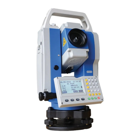
STONEX R1 PLUS User manual
STONEX
STONEX R6 Series User manual
STONEX
STONEX R2W PLUS 500 User manual
STONEX
STONEX R80 User manual
STONEX
STONEX SPL1 User manual
STONEX
STONEX R25LR User manual
STONEX
STONEX R60 User manual

STONEX
STONEX R80 User manual

STONEX
STONEX R180 User manual
STONEX
STONEX R2 PLUS User manual
Popular Measuring Instrument manuals by other brands

ACOEM
ACOEM Fixturlaser SMC BALANCER Quick tips
LOVATO ELECTRIC
LOVATO ELECTRIC DMED320 instruction manual
Rigol
Rigol DSA1000 Series Accessories User Guide
WIKA
WIKA 2XX.34 Operating & installation instructions
Agilent Technologies
Agilent Technologies E8362B Service guide
Keysight Technologies
Keysight Technologies B2900A Series Demo guide


