Sven BTR2-10 User manual

www.sven.fi
BTR2-10
2.1 Multimedia Speaker System
OPERATION
MANUAL

ENG
1
BTR2-10
1
2
2
2
5
9
10
Congratulations on your purchase of the Sven speaker system!
COPYRIGHT
© 2014. SVEN PTE. LTD. Version 1.0 (V 1.0).
This Manual and information contained in it are copyrighted. All rights reserved.
TRADEMARKS
All trademarks are the property of their legal holders.
NOTICE OF RESPONSIBILITY RESTRICTION
Despite the exerted efforts to make this Manual more exact, some discrepancies may occur. The
information in this Manual is given on «as is» terms. The author and the publisher do not bear any
liability to a person or an organization for loss or damage which has arisen from the information
contained in this Manual.
CONTENTS
1. BUYER RECOMMENDATIONS ..................................................
.............
2. PACKAGE CONTENTS.............................................................
............
3. SAFETY PRECAUTIONS ..................................................
...................
4. TECHNICAL DESCRIPTION ....................................................
................
5. PREPARATION AND OPERATION ..........................................
......................
6. TROUBLESHOOTING.................................
...............................................
7. TECHNICAL SPECIFICATIONS ....................................................
...........
1. BUYER RECOMMENDATIONS
•Unpack the device carefully. Make sure there are no accessories left in the box. Check up the
device for damage; if the product was damaged during transportation, address the firm which
carried out the delivery; if the product functions incorrectly, address the dealer at once.
•Check up the package contents and availability of the warranty card. Make sure the warranty
card has a shop stamp, a legible signature or the seller’s stamp and purchase date, and the goods
number corresponds to that in the warranty card.
• Do not switch on the speaker system immediately after you bring it into a room from environment
with negative temperature! After unpacking, the speaker system should be kept in conditions of
room temperature for at least 4 hours.
•Before installing and using the speaker system, read this Manual carefully and keep it for future
reference.
Technical support is on www.sven.fi.
2.1 Multimedia Speaker System

ENG
2
2.1 Multimedia Speaker System
2. PACKAGE CONTENTS
•Subwoofer — 1 pc
•Satellites — 2 pcs
•Audio cable — 2 pcs
•2RCA to 2RCA signal cable — 1 pc
•Remote control — 1 pc
•CR2025 battery — 1 pc
•FM antenna — 1 pc
•AM antenna — 1 pc
•Operation manual — 1 pc
•Warranty card — 1 pc
3. SAFETY PRECAUTIONS
•To avoid electric shock, do not open the MSS and do not perform repairs by yourself. Service and
repairs should be performed only by qualified specialists in an authorized service center. The list of
authorized service centers is available on www.sven.fi
•Do not allow the circuit of wires (including the grounded ones) between the speakers, on the
power amplifier or the ground, for it causes damage to the power amplifier output stage.
•Do not touch the MSS power cord plug pins for 2 seconds after unplugging it from the mains.
•Disconnect the MSS from the mains system during a fuse replacement. Use fuses of the same
type and rated value. Do not use hand-made fuses.
•Do not put foreign objects inside the holes of the MSS.
•Protect the MSS from high humidity, water and dust.
•Protect the MSS from heating: do not place it closer than 1 m from a heat source. Do not expose
it to direct sunlight.
•Do not place any open flame sources on or close to MSS.
•Do not place the MSS in poorly ventilated areas. Leave an air gap of 10 cm or more. When
operating the MSS, do not put any devices on it, do not cover it with cloth or other objects pre-
venting it from cooling.
•Do not use any chemical agents for cleaning. Clean it with dry soft cloth only.
4. TECHNICAL DESCRIPTION
BTR2-10 2.1 Multimedia Speaker System (MSS) equipped with an AM/FM tuner is designed for
playing music and sounding games, movies, etc., as well as being used as a radio tuner. Due to the
built-in amplifier, the speaker system can be connected to any audio source. Remote control is
included.
Caution! High voltage inside! To avoid the risk of electric
shock do not open or touch elements inside.

ENG
3
BTR2-10
2.1 Multimedia Speaker System
Subwoofer control panel
aDisplay screen
bMUTE: mute button
cSUB+: subwoofer volume up
dSUB–: subwoofer volume down
eRESET: default reset
fINPUT: audio source selection
gSTANDBY: standby mode button
hVOLUME: master volume control knob
Fig. 1. Subwoofer control panel
Special features
•Built-in transformer power source
•Built-in AM/FM tuner
•Two stereo AV inputs for connection to various audio devices
•Electronic audio switch
•Full-function remote control
•Master volume control, bass/midrange/treble control, subwoofer volume control
•LED display
•Magnetic shielding
•MDF subwoofer and satellites cabinets
a
b
h
g
f
e
c
d
Subwoofer rear panel (Fig. 2)
aFM ANT: FM antenna terminal
bAN GND/AM ANT: AM antenna terminals
cCD-1: audio source input
dCD-2: audio source input
e2.1CH OUTPUT: audio outputs for left
and right speakers
fPOWER: power ON/OFF switch
gPower cord

ENG
4
2.1 Multimedia Speaker System
L
L
L
R
R
R
INPUT
CD-1
CD-2
INPUT
a
b
c
d
e
f
g
Fig. 2. Subwoofer rear panel
–
–
b
c
d
e
f
g
h
i
j
k
l
m
n
o
pINPUT
TREBLE
–
TREBLE
+
+
+
MIDLE MIDLE
SUB SUB
VOL VOL
–+
SCAN
TUNE
TUNE
FM/AMMEMORY
-
+
123
010
9
8
7
654
+
STANDBY MUTE
Fig. 3. Remote control
a
Remote control
aSTANDBY: STANDBY mode button
bMUTE: MUTE button
cVOL+/-: volume control buttons
dTREBLE +: treble level up
eMIDLE +: midrange level up
fSUB +: subwoofer volume up
gSCAN: tuner auto scan
hTUNE+/-: tuner manual adjustment
iFM/AM: FM and AM band selection
jMEMORY: button for saving tuner settings
k10+: numerical keyboard multiplier
l0 – 9: numerical keyboard buttons
mSUB –: subwoofer volume down
nMIDLE –: midrange level down
oTREBLE –: treble level down
pINPUT: audio source selection

ENG
5
BTR2-10
2.1 Multimedia Speaker System
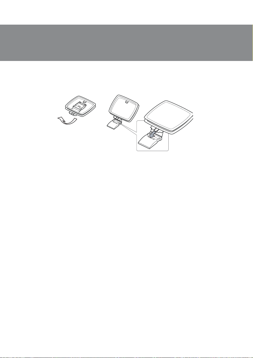
Remote control battery installation
• Open the battery compartment on the back of the remote control.
• Put in the CR2025 battery (included).
• Close the battery compartment.
Notes:
• Use the remote control at an angle no more than 30°, no more than 7 meters away.
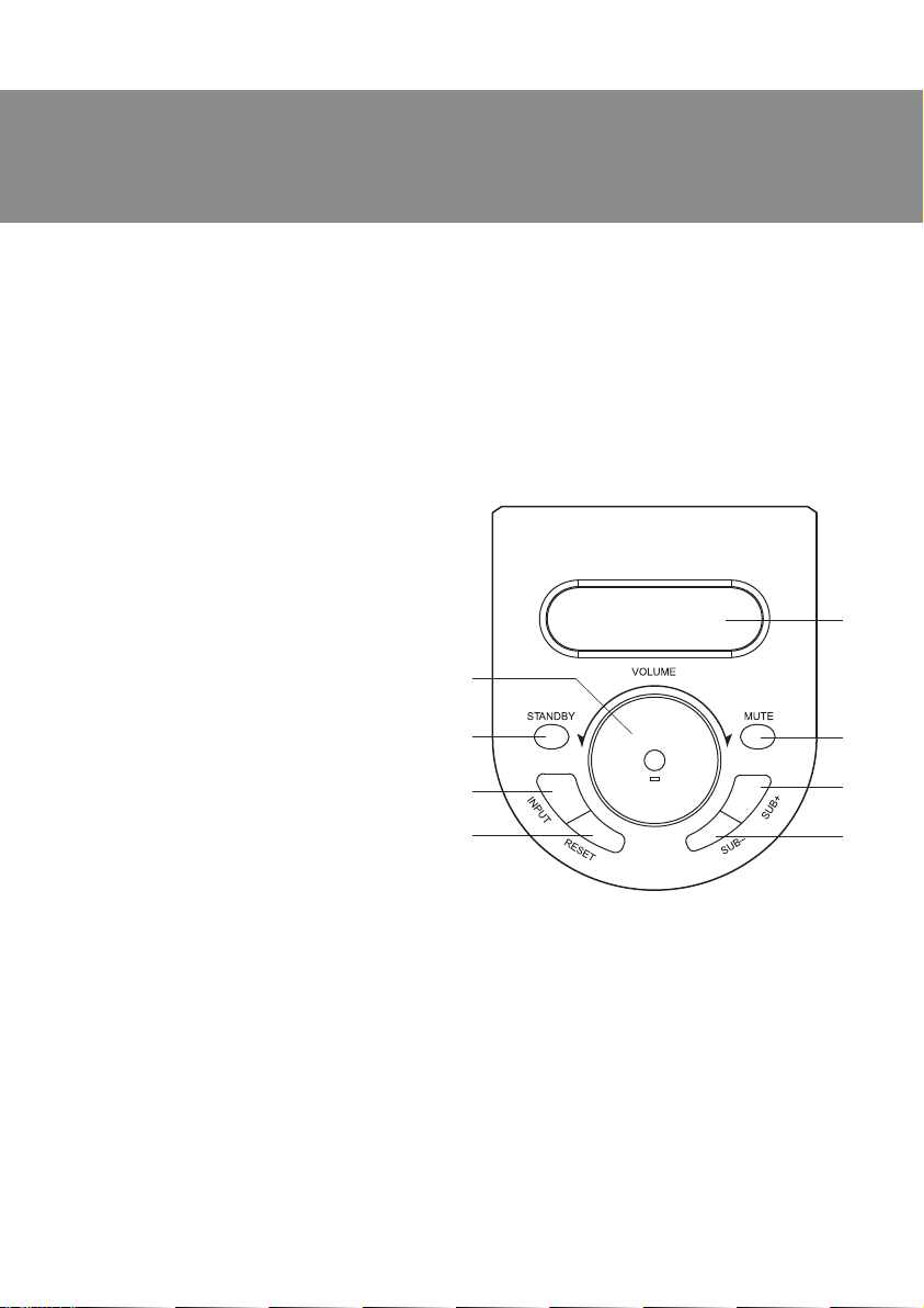
• Direct the remote control at the IR receiver display on the subwoofer.
• If the remote control does not work, check the battery or replace the discharged battery
with a new one.
• Remove the battery from the remote control if you don’t intend to use it for a long time
(more than a week).
5. PREPARATION AND OPERATION
Speaker placement
•Place the speakers symmetrically to the listener at least one meter away. The subwoofer emits
non-directional sound, therefore it can be located in any place of the room where it sounds the best.
•Place MSS far away from monitors and TV sets, as insignificant image distortion in these
supersensitive devices is possible.
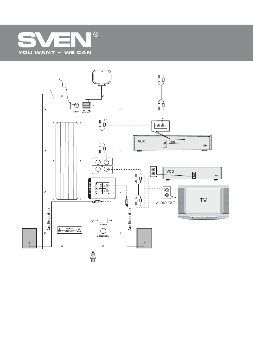
MSS сonnecting and control
BTR2-10 2.1 Multimedia Speaker System (MSS) can be attached to virtually any audio source (see
Fig. 4).
• Before connecting, make sure that the MSS is unplugged. Then, connect the subwoofer to the
satellites using the audio cables supplied (see Fig. 4), use correct polarity.
• To connect the speakers to a CD / DVD-player, TV, PC sound card, etc., use the 2RCA to 2RCA stereo
signal cable. Be sure to connect the left and right channels. Insert the left RCA-jacks into left ports of
the amplifier (usually white), and the right RCA-jacks — into right ports of the amplifier (usually red).
Note. The accuracy and reliability of the connection of cables directly affects sound
quality. Check for absence of contact between bared wires and metal parts of the
equipment.
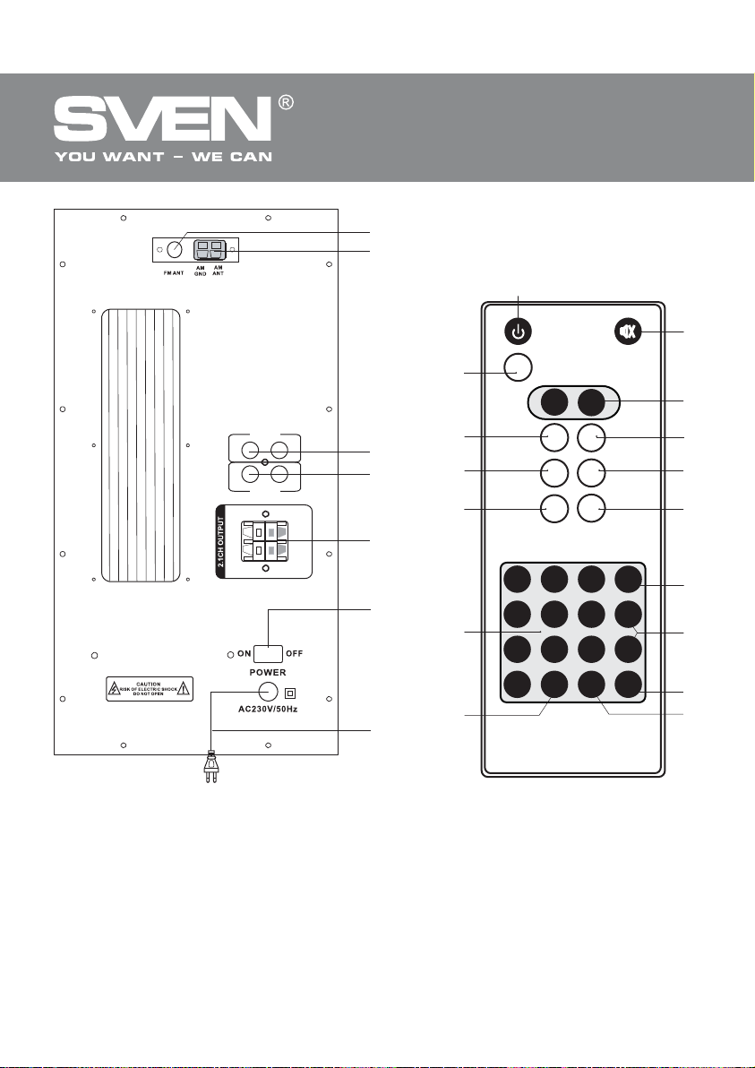
Installation and connection of antennas
FM antenna connection
• Insert the included room FM antenna into FM ANT terminal on the subwoofer rear panel, as
shown in the diagram. Install the FM antenna in such a way that reception quality is satisfactory, and
then fix the position of the antenna.
Note. External 75 Ohm FM antenna should be used for buildings with weak FM signal.
Typically, a three-element antenna is enough, but in areas with weak FM signal it is
recommended that you use an FM antenna with 5 or more elements.

ENG
6
2.1 Multimedia Speaker System
Power cord
Subwoofer
rear panel
Right
speaker
Left
speaker
2RCA to 2RCA
signal cable
L
L
L
R
R
R
INPUT
CD-1
CD-2
INPUT
FM antenna AM antenna
Fig. 4. Connection diagram

ENG
7
BTR2-10
2.1 Multimedia Speaker System
АM antenna connection
• To install the loop antenna, fix the bracket to the hole at the bottom of the antenna as shown
below, Fig. 5 (step 1).
• Turn the visor of AM terminal anticlockwise to loosen it slightly, insert the cord of the loop antenna
under the visor and turn the visor clockwise to firmly clamp the cord (step 2). Gently pull the cord to
make sure it is securely fixed. Install the antenna in a niche or hang it on the window frame, that is in
a place where reception is better. Place all other cables (power cable, speaker cables or connec-
ting wires) far away from the antenna.
• After that, connect the loop antenna to AM ANT and AM GNT terminals on the rear panel of the
subwoofer (see connection diagram, Fig. 4).
Note. When the reception is poor in the inner AM loop antenna, it is recommended that an
external AM antenna be used (not included).
Operation guide
Switching On
• To switch on the subwoofer, plug the power cord of the subwoofer into the mains outlet and shift
the POWER On/ Offswitch on the rear panel into the ON position. The display (a, Fig. 1) on the
front panel will illuminate.
Standby mode (STANDBY)
• STANDBY mode feature is designed to quickly switch on the speaker system and save power
consumption. Press STANDBY (a, Fig. 3) on the remote control or the STANDBY button (g, Fig. 1)
on the control panel to activate/deactivate this feature. If the STANDBY button is on, the
corresponding inscription on the display of the subwoofer will illuminate. Press it again, and the
speaker system will return to the operation mode.
Audio source selection
• There are two inputs (CD-1 and CD-2) on the rear panel of the MSS. To use a stereo audio source,
connect it to thуINPUT terminals cand dof the speaker system, as shown in Fig. 4.
• Depending on the required connection, select the desired audio source with the INPUT button
(p, Fig. 3) on the remote control or control panel of the subwoofer (f, Fig. 1). The corresponding
inscription on the display of the subwoofer will illuminate.
Fig. 5. АM antenna connection
12

ENG
8
2.1 Multimedia Speaker System
Turning on and setting the tuner
• Press SCAN gand FM/AM ion the remote control to turn on the tuner and select FM or AM.
• Manual setting. Press TUNE + or TUNE- buttons hon the remote control for finetuning radio
station frequency (see tuning steps in Technical Specifications).
• Auto search. By holding SCAN gon the remote control for more than 1 second, you turn on the
scanning of the FM-band starting with 87 MHz frequency, the found radio stations being memorized
sequentially: CH 01, CH 02, CH 03, etc. Scanning of the FM-band will continue until 108 MHz
frequency. After scanning, the first found radio station turns on.
• Additionally, the desired broadcast can be quickly turned on with numeric keypad buttons kand
lon the remote control, having saved systems of 20 FM radio stations and 20 AM radio stations.
To save the found radio station, press MEMORY jon the remote control (CH _ will illuminate on the
display), then enter its number (from 0 to 19) with numeric keypad buttons kand lon the remote
control, which will illuminate on the display (for example, CH 09). After saving the required quantity
of radio stations, enter the number of the desired radio station on the remote control with numerical
keypad buttons kand lfor quick search.
Volume control
• Press VOL+ or VOL– (c, Fig. 3) on the remote control or turn the VOLUME knob (h, Fig. 1) on
the front panel of the subwoofer to regulate (increase/decrease) volume level.
Bass, midrange, and treble control
• Level of bass, midrange and treble is adjusted with buttons TREBLE+ dand TREBLE– o, MIDLE+
eand MIDLE– n, SUB+ fand SUB– mon the remote control. Bass level can be also adjusted
with SUB+ cand SUB– don the front panel of the subwoofer.
Mute feature
• Press MUTE bon the remote control or the same button on the subwoofer control panel to
temporarily turn offthe sound. Press this button again to turn on the sound.
Note. If the speaker system is not used for a long time, mind to switch off the device by using
the POWER On/Off switch and unplug it.

ENG
9
BTR2-10
2.1 Multimedia Speaker System
6. TROUBLESHOOTING
If none of the above methods can solve the problem, please seek professional advice at your
nearest service center. Never attempt to repair the product yourself.
Problem
The MSS does not
turn on.
No sound.
There is too quiet
sound of speakers.
Distortion of
sound.
Remote control is
not working.
FM/AM tuner is
not working.
Cause
The MSS isn’t connected to a mains outlet.
Power switch is off.
Volume level is set at minimum value.
Improperly connected audio source.
Volume level is set at minimum value.
Large amplitude of the input signal.
The battery is discharged.
There is direct sunlight.
Obstacle between the remote control and
the subwoofer receiver.
FM/AM tuner is not connected.
Poor reception of antennas.
Solution
Check the connection.
Turn on the switch.
Adjust the volume control knob.
Connect audio sources correctly.
Adjust the volume control knob.
Turn down the source volume
and MSS volume.
Replace the battery with a new one.
Change the location of the
subwoofer or remote control.
Change the subwoofer or remote
control location.
Connect the FM/AM antenna.
Connect an external FM antenna
or AM antenna.

10
2.1 Multimedia Speaker System
ENG
Parameter, measurement unit
Output power (RMS), W
subwoofer
satellites
Frequency response, Hz
subwoofer
satellites
S/N ratio, dB
Speaker diameters, mm
subwoofer
satellites
Power supply, V/Hz
Dimensions (W × H × D),mm
subwoofer
satellites
Weight, kg
Frequency bands:
АМ (at 9 kHz step), kHz
АМ (at 10 kHz step), kHz
FМ(at 100 kHz step), MHz
S/N ratio:
AM, dB
FМ, dB
Value
80 (50 + 2 × 15)
50
2 × 15
20 – 120
120 – 20 000
≥70
Ø 165
Ø 38 + Ø 102
~220/50
220 × 400 × 340
140 × 240 × 150
12.0
522 ~ 1611
530 ~ 1610
87 ~ 108
≥30
≥40
Speaker system
Tuner
7. TECHNICAL SPECIFICATIONS
Notes:
•Technical specifications given in this table are supplemental information and cannot give
occasion to claims.
•Technical specifications and package contents are subject to change without notice due
to the improvement of SVEN production.

2.0 Multimedia Speaker System
Automatic Voltage Regulator
Стабилизатор напряженияСтабилизатор напряжения
Automatic Voltage Regulator
2.0 Multimedia Speaker System2.0 Multimedia Speaker System
SPS-619
BTR2-10
2.1 Multimedia Speaker System
Модель:
BTR2-10
Импортер вРоссии: ООО «СКАНДИТРЕЛ», 111024, РФ,
г. Москва, ул. Авиамоторная, д. 65, стр. 1.
Уполномоченная организация вРоссии: ООО «РТ-Ф»,
105082, г. Москва, ул. Фридриха Энгельса, д. 75, стр. 5.
Условия гарантийного обслуживания смотрите
вгарантийном талоне или на сайте
www.sven.fi.
Гарантийный срок: 12 мес.
Срок службы: 5 лет.
Производитель: «СВЕН ПТЕ. Лимитед»,
176 Джу Чиат Роуд, №02-02, Сингапур, 427447.
Произведено под контролем «Свен Скандинавия
Лимитед», 48310, Финляндия, Котка,
Котолахдентие, 15. Сделано вКитае.
Manufacturer: SVEN PTE. LTD, 176 Joo Chiat Road,
№02-02, Singapore, 427447. Produced under the
control of Oy Sven Scandinavia Ltd. 15, Kotolahdentie,
Kotka, Finland, 48310. Made in China.
® Registered Trademark of Oy SVEN
Scandinavia Ltd. Finland.
Table of contents
Other Sven Speakers System manuals