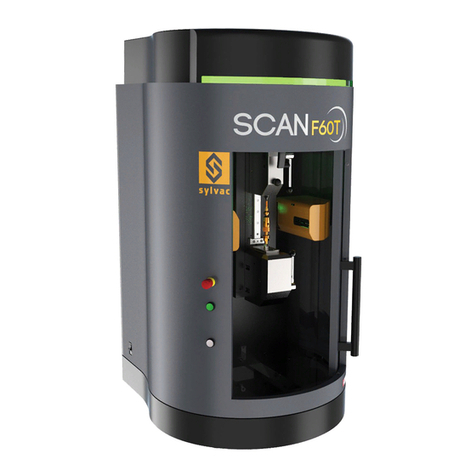
Sylvac SCAN F60 User manual
Other Sylvac Measuring Instrument manuals
Sylvac
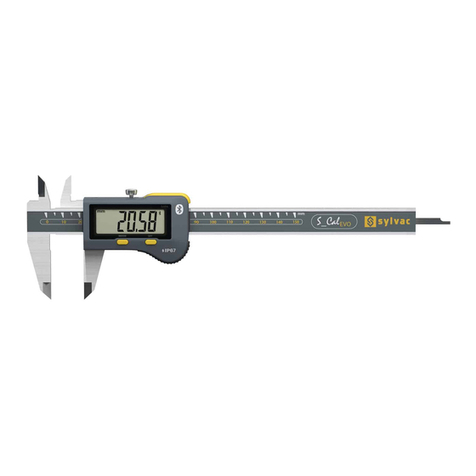
Sylvac EVO Bluetooth User manual
Sylvac
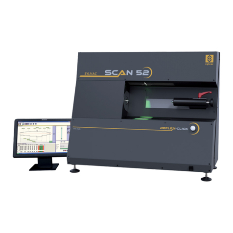
Sylvac SYLVAC-SCAN 52 REFLEX-CLICK User manual
Sylvac
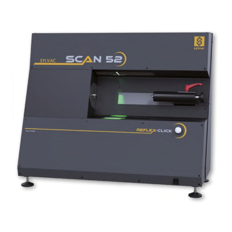
Sylvac SCAN 52 User manual

Sylvac
Sylvac UL 4 User manual
Sylvac
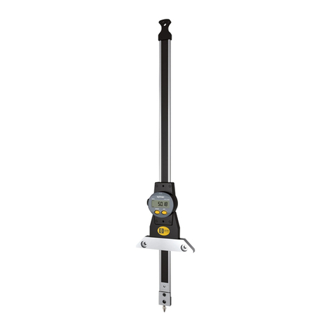
Sylvac S Depth PRO User manual
Sylvac
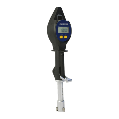
Sylvac Bowers XTL User manual
Sylvac
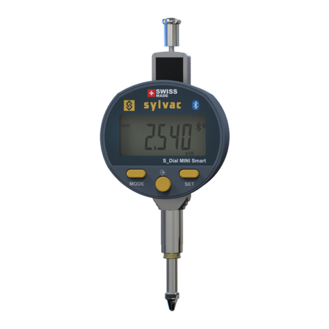
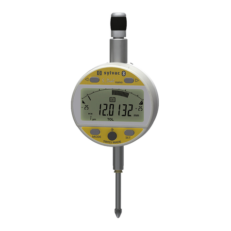
Sylvac S Dial WORK ANALOG NANO Smart User manual

Sylvac
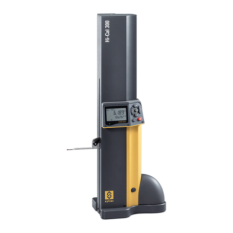
Sylvac 810.9707 User manual
Sylvac
Sylvac Hi Cal User manual
Sylvac
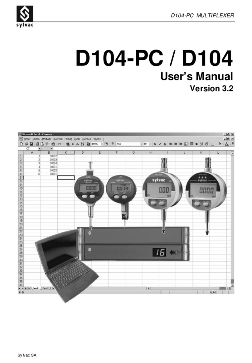
Sylvac D104-PC User manual
Sylvac
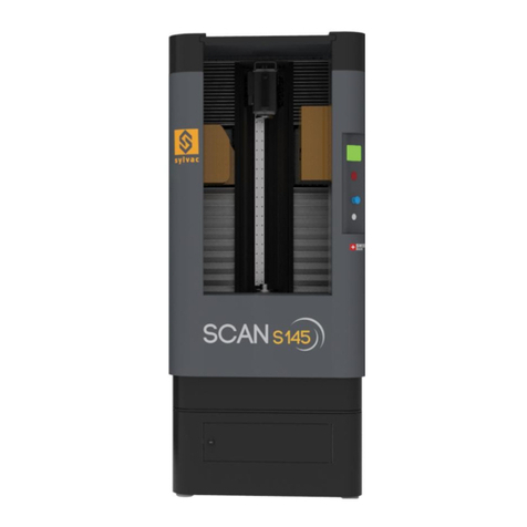
Sylvac SYLVAC-SCAN S145 User manual
Sylvac
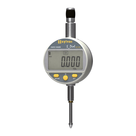
Sylvac S Dial WORK User manual
Sylvac
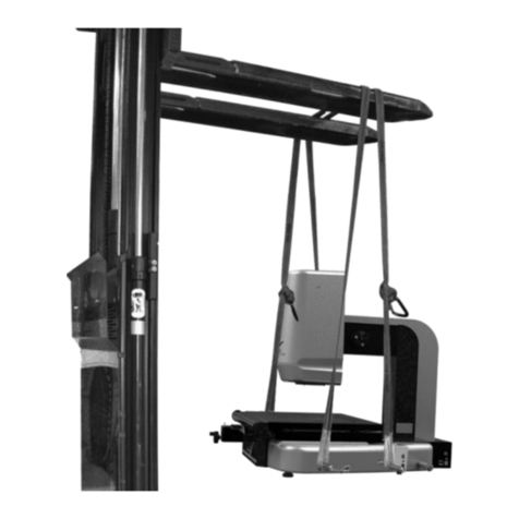
Sylvac SYLVAC-VISIO 300 GL User manual
Sylvac
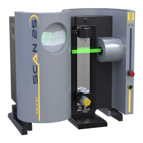
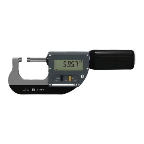
Sylvac Scan Series User manual
Sylvac
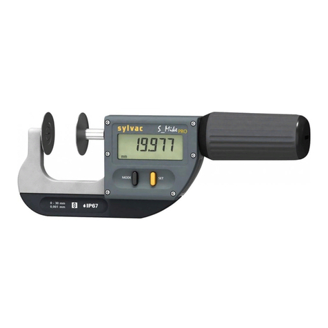
Sylvac S Mike PRO User manual

Sylvac
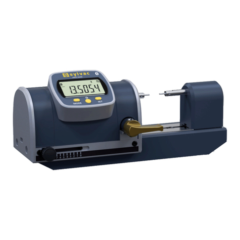
Sylvac Hi Gage ONE Smart User manual
Sylvac
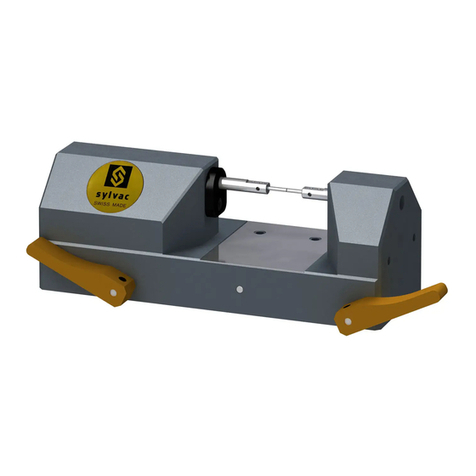
Sylvac PS16 V2 User manual
Sylvac
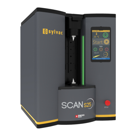
Sylvac PS15 User manual
Sylvac
Sylvac S25 User manual
Sylvac
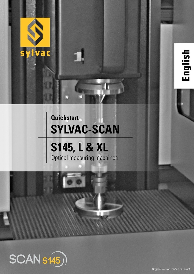
Sylvac SYLVAC-SCAN S145 XL User manual
Popular Measuring Instrument manuals by other brands

Powerfix Profi
Powerfix Profi 278296 Operation and safety notes

Test Equipment Depot
Test Equipment Depot GVT-427B user manual

Fieldpiece
Fieldpiece ACH Operator's manual

FLYSURFER
FLYSURFER VIRON3 user manual

GMW
GMW TG uni 1 operating manual

Downeaster
Downeaster Wind & Weather Medallion Series instruction manual

Hanna Instruments
Hanna Instruments HI96725C instruction manual

Nokeval
Nokeval KMR260 quick guide

HOKUYO AUTOMATIC
HOKUYO AUTOMATIC UBG-05LN instruction manual

Fluke
Fluke 96000 Series Operator's manual

Test Products International
Test Products International SP565 user manual

General Sleep
General Sleep Zmachine Insight+ DT-200 Service manual
