4
Fig. 2 Fig. 3
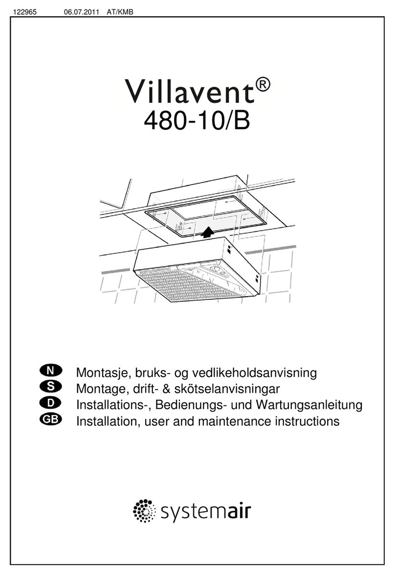
Alternativ 1. Montering i ventilatorskap
Vifteenheten festes til ventilatorskapet med 4 stk.
skruer (4,5x16 mm, "F" i fig. 1). Bruk vedlagt
hullmal (sjablon) til å merke av festehullene.
Hullmalen legges først på skapets høyre innerside,
slik at malens side, som er merket "A",
sammenfaller med bakveggen i skapet. Bor opp
pkt. 1 og 2, avmerket på malen. Bor deretter opp
venstre sides festehull på samme måte. Festene
bores opp med Ø2 mm bor.
NB! Dersom kjøkkenskapene har 20 mm
veggtykkelse, må de 2 distansestykkene på
hver side av vifteenheten fjernes.
Alternativ 2. Montering til krydderhylle
Festepunktene på hvert sideskap må fôres ut 16
mm, eller tilsvarende veggtykkelsen i et
ventilatorskap. Fremgangsmåte for øvrig som
beskrevet i alt. 1.
Alternativ 3. Montering i overskap
Det må lages en passende utsparing i bunnen av
skapet. Fremgangsmåte for øvrig som beskrevet i
alt. 1.
Alt. 1: Installation in ventilation cupboard
The fan unit is fixed to the ventilation cupboard by
means of 4 screws (4,5x16 mm "F" on fig. 1). Use
the enclosed template to mark off the points for the
fixing holes.
First hold the template towards the right inner side
of the ventilation cupboard, so that the template side
marked "A" fits against the back wall. Drill holes
marked 1 and 2 on the template. Then drill the holes
on the left inner side of the cupboard. Use a Ø2 mm
drill bit.
NOTE! If the cupboard walls are 20 mm thick, the
2 spacers on the sides of the fan unit must
be removed.
Alt. 2. Installation to spice rack
Mounting instructions as in alt 1, but the space
between the side walls and the ventilation unit
must be filled in (16 mm).
Alt. 3. Installation in kitchen cupboard
A suitable opening has to be made in the bottom of
the cupboard. Further installation instructions as for
alt.1.
PLASSERING AV FESTESKRUER I VIFTEENHETEN
Vifteenheten skrus fast til overskap fra innsiden
etter at filterplaten "H" (fig.2) først er løsnet.
Filterplaten løsnes ved å skyve plastlåsene "L"
(fig. 2) mot hverandre
Skaptilpassing
Uansett montasjealternativ skal alltid skapfront
være i flukt med vifteenhetens uttrekksdel, når
denne er innskjøvet.
Tilpassing gjøres ved å løsne skruene "M" og
skyve de firkantede platene "P" til riktig posisjon.
Lås til slutt ved å skru til skruene "M" igjen (fig. 3).
MOUNTING FIXING SCREWS IN THE FAN UNIT
Remove filter, "H" (fig. 2) by pushing the 2 filter
locks inwards. Screw the ventilation unit to the
cupboard walls from the inside. Loosen filterplate by
pushing the filter locks "L" inwards.
Adjusting to cupboard
The depth of the unit can be varied to match the
facia cover flush with the cupboard front, with the
extendable sectors in the pushed-in position.
Adjust stop position by loosening the screws "M"
and push the plates "P" to correct position.
Remember to tighten the screws "M" after the
adjustment (fig. 3).
ELEKTRISK TILKOBLING
Vifteenheten leveres med ledning og jordet støpsel
(rundstift 10/16A), og skal bare tilkobles en 10A
eller 16A /230 V jordet stikkontakt.
ELECTRICAL CONNECTION
The ventilation unit is supplied with cable and
earthed plug for connection to mains supply (10 A
or 16 A/230V. For the UK market 13 A/240 V).
