manuals.online logo
Brands
  1. Home
  2. •
  3. Brands
  4. •
  5. System air
  6. •
  7. Ventilation Hood
  8. •
  9. System air VR-700E Instruction Manual

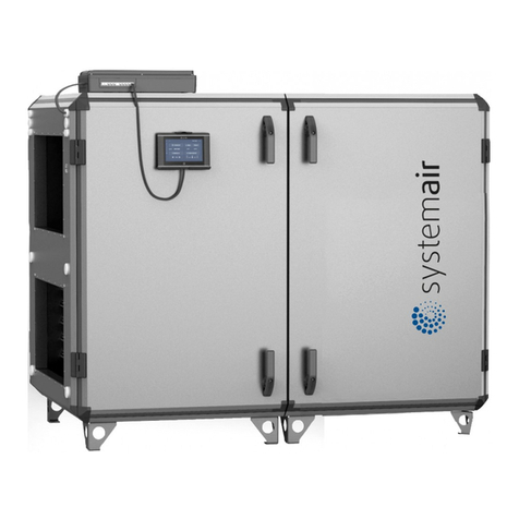
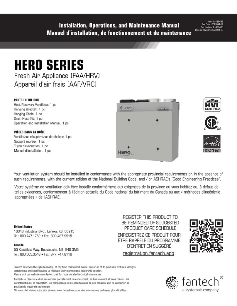
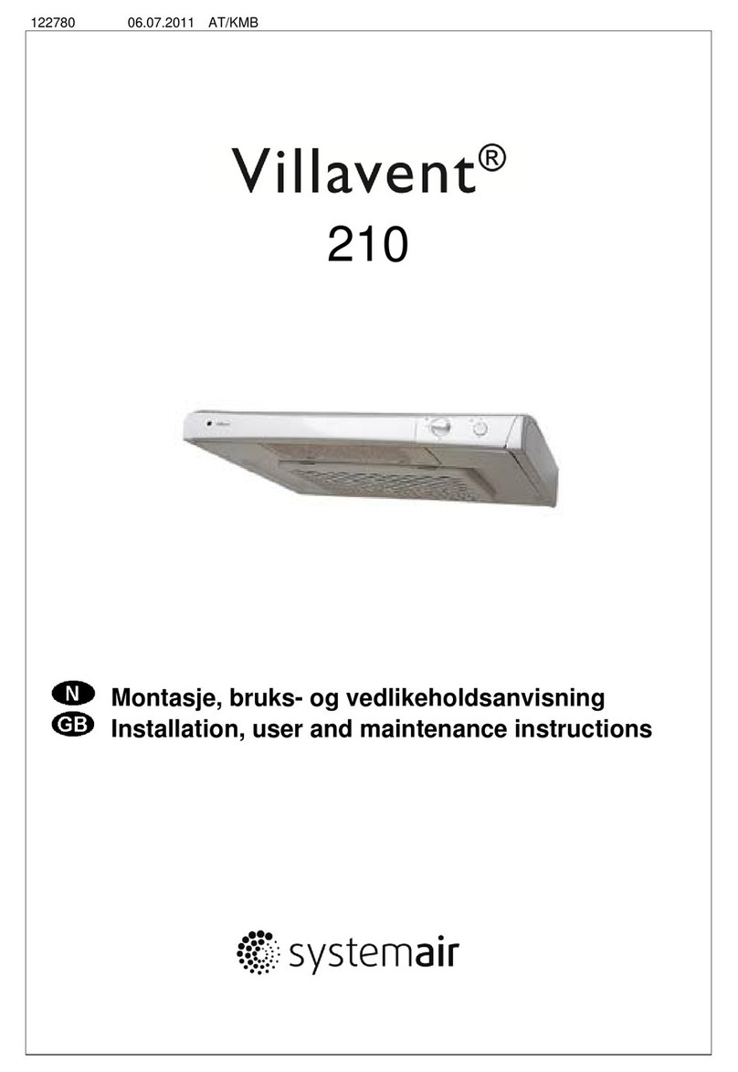
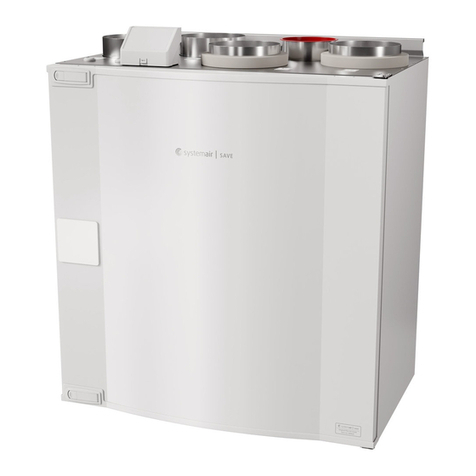
System air VR-700E Instruction Manual

VR-700 E/EC
Bedienungs- und Wartungsanleitung
User and maintenance instructions
Systemair GmbH DEZ. 2006
2
EINLEITUNG
Villavent Lüftungs- und Wärmerück-
gewinnungsanlagen werden seit 1980
produziert. Diese Geräte sind und werden in
Tausenden von Gebäuden in Norwegen und
Großbritannien eingesetzt.
Alle Erfahrungen aus diesen Anwendungen
haben wir in die Villavent VR-700 E/EC
Geräte einfließen lassen. Ebenso wurde die
letzte Untersuchung über den Zusammenhang
zwischen Innenraumklima und dem
menschlichen Wohlbefinden berücksichtigt.
Große Beachtung gilt der Qualitätssicherung.
Trotz aller gewonnenen Erfahrung und größter
Sorgfalt bei der Entwicklung hängt das
letztendliche Ergebnis immer von der Sorgfalt
bei der Installation und dem Gebrauch ab.
Diese Anleitung soll Ihnen bei der Bedienung
und der Wartung helfen.
INHALT
A
LLGEMEINES
Seite 5
B
EDIENUNG
Seite 8 und 20
A
CHTUNG
Seite 12
W
ARTUNG
Seite 14 und 16
F
EHLERSUCHE
Seite 18
K
UNDENDIENST
Seite 23
INTRODUCTION
Villavent have been manufacturing heat
recovery units since 1980. The units are
installed in thousands of buildings in Norway,
with increasing numbers in the U.K.
Experience from these installations is
incorporated in our unit, the Villavent
VR-700 E/EC. The latest results from the
studies of the indoor climate and its influence
on our health are taken into consideration, and
great emphasis is given to quality and
performance.
However, even after we have put all our
experience into developing the unit, the final
result depends on the quality of the total
installation and maintenance described in this
booklet.
INDEX
G
ENERAL
page 5
O
PERATION
page 8 and 20
W
ARNING
page 12
M
AINTENANCE
page 14 and 16
T
ROUBLESHOOTING
page 18
S
ERVICE
page 23
3
Fig. 1
Fig. 2
1.)Zentralgerät
2.)Schalldämpfer
4.)Außen-/Frischluftöffnung
5.)Abluftöffnung (Dachhaube)
6.)Zuluftventil in Wohn- und Schlafräume
7.)Abluftventile in Nassräumen
8.)Entlüftung Abwasserrohr (Option)
9.)Flexible Kanäle (nur Ausnahme)
10.)Spirorohr
11.)Dämmung
1.)Unit
2.)Silencers, inlet/extract
4.)Fresh air intake
5.)Discharge extract air
6.)Inlet diffusers in living rooms
7.)Extract louvres in wet rooms
8.)Soil vent pipe if installed
9.)Flexible ducting
10.)Spiro ducting
11.)Duct insulation
A.) Zuluftgebläse
B.) Abluftgebläse
C.) Wärmetauscher
D.) Frischluftfilter
E.) Abluftfilter
F.) Bedienteil
A.) Inlet fan
B.) Extract fan
C.) Heat exchanger
D.) Fresh air filter
E.) Extract filter
F.) Control panel
4
ALLGEMEINES
Villavent Geräte VR-700 E/EC sind komplette
Belüftungsanlagen zur Lieferung von
gefilterter und vorgewärmter Außenluft bei
Abzug einer gleichen Menge verbrauchter Luft
aus dem Gebäude.
Die Geräte sind mit einem Wärmetauscher
aus Aluminium, sowie mit Steuerungs-
funktionen, die eine sichere und wirtschaft-
liche Belüftung gewährleisten ausgerüstet.
GENERAL
Villavent VR-700 E/EC are complete
ventilation units for supply of filtered and
preheated outdoor air to residential areas and
extract of a corresponding amount of used air
from WC, bathroom and wet rooms.
The unit is equipped with a heat exchanger in
aluminium and control functions to ensure
safe and economical ventilation.
Fig. 3
BEDIENUNG (Fig. 3)
Die Anlage wird über eine integrierte und
eine oder mehrere Fernbedienungen mit
folgenden Funktionen betrieben:
Luftvolumenstrom (Ventilatordrehzahl)
Tasten für die Wahl von 3 Stufen. Erhöhen/
Senken der Drehzahl durch drücken der Tasten
(4) bzw (5). Die Leuchten(1), (2) und (3) zeigen
die eingestellte Stufe.
Min (1) kleinste Stufe. Während Ferien oder
wenn sich niemand im Haus aufhält.
Norm (2) normale Stufe. Der Zuluftvolumen-
strom in der Normalstufe wird ent-
sprechend der Gebäudegröße ausge-
wählt. Dies geschieht während der
Inbetriebnahme der Anlage.(siehe
Montageanleitung – Inbetriebnahme)
Max (3) größte Stufe. Kann eingestellt
werden, wenn ein höherer
Luftwechsel nötig ist.
OPERATION (Fig. 3)
The unit is equipped with an integrated
control panel. In addition operation can be
made from one or more remote controllers, all
with the following functions:
Airflow (Fan speed)
Switches for choice of airflow in 3 steps.
Increase/decrease fan speed by pressing the
switches (4) and (5) alternatively. Lamp signals (1),
(2) and (3) show set airflow.
Min (1) Minimum ventilation. To be used during
holidays or when the building is not in
use.
Norm (2) Normal ventilation. The air volume at
normal ventilation is set in accordance
with the size of the building. This is
done during commissioning of the
system (see installation instructions -
Commissioning).
Max (3) Forced ventilation. Is used when extra
airflow is required.
5
"Sommerbetrieb" und Zulufttemperatur
Tasten für Einstellung der max. Zulufttemp. Die
Zulufttemperatur kann in 5 Stufen (16-22°C) mit
den Tasten (9) + (10) nach oben/unten verstellt
werden. Die Lampen (6), (7) + (9) zeigen den
eingestellten Wert an.
Stufe 1 Lampe (6) leuchtet
Stufe 2 Lampen (6) + (7) leuchten
Stufe 3 Lampe (7) leuchtet
Stufe 4 Lampen (7) + (8) leuchten
Stufe 5 Lampe (8) leuchtet
Sobald die rückgewonnene Wärme aus der
Abluft nicht mehr ausreicht die eingestellte
Temperatur zu erreichen, schaltet sich auto-
matisch ein elektr. Nachheizrgister ein.
Die Lampe (14) leuchtet bei betrieb des NHR.
(Wir empfehlen die Zulufttemperatur so niedrig
als möglich einzustellen, jedoch so, daß Zugluft
vermieden wird. Hierdurch erhalten Sie die
größtmögliche Energieausbeute und den
besten Lüftungseffekt).
Filter
Die Lampe (11) leuchtet, wenn die Filter-
Standzeit abgelaufen ist (E, Fig.1). Die Lampe
(11) leuchtet auch, wenn das Gerät die Luft-
mengenbalance nicht halten kann (z.B. ein
Filter verstopft). Achtung! Störungen der
Luftmengen können auch auftreten, wenn die
Ventile verstellt werden oder das Außen-
ansauggitter verstopft ist. Das WRG-Gerät
kann auch ohne Filterwechsel weiterlaufen,
jedoch sinkt der Wirkungsgrad immer weiter
und der Luftmengenabgleich kann evtl. nicht
mehr erreicht werden. (es kann ein Unterdruck
bzw. Überdruch im Gebäude entstehen.). Die
Standzeit (6,9 oder 12 Monate) kann an der
Steuerung eingestellt werden (Montage-
anleitung). Die Filter-Standzeit muß nach dem
Wechsel neu aktiviert werden (siehe Wartung,
Punkt 1).
”Sommerbetrieb”
Sobald die Zulufttemperatur die eingestellte
Temp. übersteigt, bleibt der Rotor stehen und
es findet kein Wärmeaustausch mehr statt
(Sommerfunktion). Liegt die Ablufttemperatur
unter der Außenlufttemp. (wenn das Gebäude
klimatisiert ist), läuft der Rotor wieder an und
die Abluft kühlt die Zuluft im Tauscher. Die
Lampe (12, Fig.3) leuchtet solange der Rotor
steht.
"Summer operation" and supply air
temperature
Switches for choice of max inlet air temperature.
Supply air temperature is increased/ decreased
in 5 steps by pressing switch (9) and (10)
alternatively. Lamp signals (6), (7) and (8) show
set supply air temperature.
Step 1 Lamp (6) lights
Step 2 Lamp (6) and (7) light
Step 3 Lamp (7) lights
Step 4 Lamp (7) and (8) light
Step 5 Lamp (8) lights
When heat recovery from the extract air is in-
sufficient to obtain set supply air temperature, an
electrical heater battery will automatically be
switched on.
Lamp signal (14) will light up when the heater
battery is in operation. (In general it is re-
commended to set supply air temperature as low
as possible, avoiding the feeling of draught. This
gives the ultimate energy and ventilation
efficiency).
Filter
Lamp signal (11) comes on when set operation
time between changing of filters (E, fig. 1) has
expired. The lamp (11) will also light up if the unit
cannot maintain the correct air balance, f.ex. if
one of the filters is clogged. NOTE! Changes in
the air balance may also occur if the setting on
diffusers/louvers is being changed, if the fresh air
intake is clogged or similar. The ventilation unit
can still be operated, but the efficiency will be
reduced and the air balance in the building will be
changed (to increased over- or underpressure,
depending on which filter is being clogged) if the
filters are not replaced. Operation time (6, 9 or 12
months) between filter changes can be set on the
control panel (see installation instructions). Reset
operation time after having changed the filters
(see
MAINTENANCE
, item 1).
"Summer operation"
When supply air temperature exceeds set
temperature, the rotor will stop and there will be
no heat recovery (summer operation). If the
extract air temperature becomes lower than the
outdoor temperature (f.ex. if the building has
cooling/air conditioning installed), the unit will
automatically switch to recovery (of the chilled
indoor air). The extract air will then cool down the
inlet air in the exchanger. Lamp (12, fig. 3) lights
when the rotor is not in operation.
6
Manueller Sommerbetrieb
In Frühling und Herbst kann es trotz niedriger
Außentemperatur sein, dass die Raumtempera-
tur durch Sonnenschein höher ist als
gewünscht. Hier kann eine niedrigere
Raumtemperatur durch senken der
Temperatureinstellung auf Stufe 0 (keine der
Lampen 6. 7 oder 8 leuchtet) und gleichzeitiges
Erhöhen der Drehzahl (max) erreicht werden.
Um zu verhindern, dass das Gerät im
manuellen Sommerbetrieb weiterläuft wenn
Wärmerückgewinnung erwünscht ist, schaltet
das Gerät bei einer Zulufttemperatur unterhalb
5°C wieder auf normalen Betrieb um.
Betrieb über Zeitschaltuhr
Wenn die Anlage in Gewerberäumen installiert
ist, wird üblicherweise über eine Zeitschaltuhr
ein abgesenkter Betrieb außerhalb der
Geschäftszeiten gefahren. Soll während des
Absenkbetriebes die Anlage im Normalbetrieb
fahren, drücken Sie die Party-Taste (13, Fig.3)
auf der Steuerung. Die Anlage läuft dann für 3
Std. im Normalbetrieb und schaltet dann
automatisch auf Absenkbetrieb zurück.
Die Anlage sollte kontinuirlich arbeiten und
nur zur Wartung und Reinigung
ausgeschalten werden.
Manual summer operation
Even if the outdoor air temperature is low, the
room temperature could be higher than wanted,
due to sunshine (spring and autumn). Lower
room temperature can be obtained by setting the
supply air temperature to a step 0, and at the
same time increase the airflow to MAX. In that
case lamps (6), (7), (8) or (14) will never come
on. Remember to adjust back to normal
settings in the evening when the room
temperature reaches normal level.
Operation from timer
When the unit is installed in commercial
buildings, it might be necessary to install a
separate week timer for automatic day and night
operation (reduced ventilation). If the building is
in use when night operation is in function,
override to day operation can be obtained by
pressing button (13, fig. 3) on the control panel.
The unit automatically switches back to operate
according to timer settings after 3 hours.
The system should operate continuously, and
only be stopped for maintenance and service.
7
1.)
2.)
3.)
4.)
Fig. 4
5.)
ACHTUNG (Fig. 4)
Zur Vermeidung von Stromstößen, Brand oder
sonstigen Beschädigungen, die durch
unsachgerechten Gebrauch oder Betrieb der
Anlage auftreten könnten, ist es wichtig,
folgendes zu beachten:
1. Die Anlage muß entsprechend der
Installationsanweisung aufgebaut werden.
2. Vor dem Warten oder Reinigen der Anlage
diese vom Stromnetz trennen.
3. Ein Wäschetrockner darf nicht unmittelbar
am Belüftungssystem angeschlossen
werden.
4. Vor Inbetriebnahme des Systems
sicherstellen, daß die Filter richtig eingesetzt
worden sind.
5. Die Wartung muß regelmäßig durchgeführt
werden.
WARNING (Fig. 4)
In order to avoid electrical shock, fire or other
damage which might occur in connection with
faulty use and operation of the unit, it is
important to consider the following:
1. The system must be installed according
to installation instructions.
2. Insulate mains supply before service or
cleaning of the heat recovery unit.
3. Tumble dryer must not be connected
directly to the ventilation system.
4. Make sure that filters are mounted in their
place before running the system.
5. Maintenance must be performed
according to separate instructions.
8
1.)
Fig. 5
2.)
WARTUNG (Fig. 5)
Die Wartung des VR-700 E/EC sollte
normalerweise 3 - 4 mal pro Jahr vorgenommen
werden. Neben der allgemeinen Reinigung
sollte folgendes beachtet werden:
1. Auswechseln des Zu- und Abluftfilters
(sobald die Signalleuchte auf der
Steuerung leuchtet, ca. 1-2 mal pro Jahr,
bzw. nach Bedarf)
Die Taschenfilter können nicht gereinigt
werden, sondern müssen erneuert werden. Die
Filterstandzeit muß nach jedem Wechsel wieder
aktiviert werden: Drücken der Taste 13 (fig. 3)
für ca. 5 sek. Die gelbe Leuchte (14) und eine
der grünen Leuchten (6,7 oder 8 - von der
gewählten Standzeit abhängig) blinken ein paar
mal auf.
Filterstandzeiten ändern
Abhänging vom Zustand des Filters kann es
nötig sein, den Wechselintervall zu ändern.
Siehe Montageanleitung ”Inbetrieb-
nahme/Grundeinst.“.
Fragen Sie Ihren Lieferanten nach neuen Filtern
2. Überprüfung des Wärmetauschers
(einmal pro Jahr)
Auch wenn die vorgeschriebene Wartung
gemäß Punkt 1 durchgeführt wird, wird sich
dennoch Staub im Austauscherblock
ansammeln. Zwecks Aufrechterhaltung der
hohen Leistungsfähigkeit ist es unerläßlich, den
Austauscherblock regelmässig auszubauen und
zu reinigen. In heißer Seifenlauge abspülen.
Kein ammoniakhaltiges Spülmittel verwenden
Achtung! Stellen Sie sicher, daß der Antriebs-
motor des Tauschers keiner
Feuchtigkeit ausgesetzt ist.
MAINTENANCE (Fig. 5)
Maintenance of the VR-700 E/EC should
normally be performed 3 - 4 times a year.
Apart from general cleaning the following
should be observed:
1. Changing fresh air/extract filter (lamp
signal on control panel, 1-2 times per
year or as necessary)
The bag filters cannot be cleaned and must
be changed as necessary. Operation time
between filter changes must be re-set after
filter change. Press button 13 (fig. 3) for apx.
5 seconds. Yellow lamp (14) and one of the
green lamps (6, 7 or 8, depending on chosen
operation time) will flash for a few seconds.
Changing operation time between filter
changes
Depending on the condition of the filter, you
might need to change the operation time for
the filter. See Installation instructions -
"Commissioning".
Contact your supplier for new filter.
2. Checking the heat exchanger (Once a
year)
Even if the required maintenance in item 1 is
carried out, dust may build up in the
exchanger block. It is therefore of vital
importance for the upkeep of a high
efficiency that the exchanger block is re-
moved from the unit and cleaned
periodically. Wash in hot soapy water. Do
not use detergent containing ammonia.
Note! Make sure that the rotor motor is not
expelled to moisture.
9
3.)
Fig. 6
4.)
5.)
6.)
WARTUNG (Fig. 6)
3. Überprüfung der Gebläse (jährlich)
Auch wenn die vorgeschriebene Wartung, wie
Auswechseln der Filter, durchgeführt wird, wird
sich dennoch Staub und Fett langsam in den
Gebläsen (4 und 5) ansammeln und die
Leistung mindern.
Die Gebläse lassen sich mit einem weichen
Tuch oder Pinsel reinigen. Kein Wasser
verwenden! Zur Beseitigung von Fett hat sich
Brennspiritus bewährt. Vor Wiedereinbau gut
trocknen lassen.
4. Reinigung der Abluftventile und
Luftauslässe (sofern erforderlich)
Das System versorgt Ihr Heim mit Frischluft und
zieht die verbrauchte Innenluft über das Kanal-
system mit Ventilen ab. Luftauslässe und
Abluftventile befinden sich in den Decken bzw.
Wänden von Schlaf- und Wohnzimmern,
Naßzellen, WC usw. Luftauslässe und Ventile
ausbauen und nach Bedarf in heißer
Seifenlauge abspülen. (Luftauslässe und
Abluftventile dürfen nicht vertauscht werden).
56. Wartung des Ansaugstutzen
Rückstände und Schmutz können das Ansaug-
gitter der Außenluft verstopfen und die
Luftleistung des Gerätes verringern. Überprüfen
sie den Zustand des Ansauges 1-2 mal pro
Jahr und Reinigen Sie ihn nach Bedarf.
Ansaug: Je nach Ausführung handelt es sich
um eine Dachhaube oder ein Wandgitter.
6. Überprüfung des Luftkanalsystems (alle
5 Jahre)
Auch bei Durchführung der erforderlichen Wart-
ung, wie Auswechseln der Filter, werden sich
Fettablagerungen im Kanalsystem aufbauen
und die Leistung mindern. Folglich sollten die
Kanalläufe nach Bedarf gereinigt bzw.
MAINTENANCE (Fig. 6)
3. Checking the fans (once a year)
Even if the required maintenance, such as
changing of filters is carried out, dust and
grease may slowly build up inside the fans (4
and 5). This will reduce the efficiency.
The fans may be cleaned with a cloth or a soft
brush. Do not use water. White spirit can be
used to remove obstinate settlements. Allow
to dry properly before remounting.
4. Cleaning extract louvres and inlet
diffusers (as necessary)
The system supplies fresh air to your home
and extracts the used indoor air via the duct
system and diffusers/louvres. Diffusers and
louvres are mounted in ceilings/walls in
bedrooms, living room, wetrooms, WC etc.
Remove diffusers and louvers and wash in hot
soapy water as required. (Diffusers/ louvres
must not be exchanged).
5. Checking the fresh air intake
Leaves and pollution could plug up the air
intake grille and reduce the capacity. Check
the air intake grille at least twice year, and
clean as necessary.
6. Checking the duct system (every 5
years)
Dust and grease settlements may, even if
required maintenance such as changing of
filters is being carried out, build up in the duct
system. This will reduce the efficiency of the
installation. The duct runs should therefore be
10
ausgewechselt werden. Stahlkanäle lassen sich
reinigen durch Entlangziehen einer mit
Seifenlauge getränkten Bürste durch den
Kanal, und zwar über die Diffuser- und
Ventilöffnungen, oder über besondere
Kontrollklappen im Kanalsystem (sofern
vorgesehen).
ACHTUNG! Zusätzlich muss die Dachhaube
einmal jährlich überprüft und falls
notwendig, gereinigt werden.
cleaned/ changed when necessary. Steel
ducts can be cleaned by pulling a brush
soaked in hot soapy water, through the duct
via diffuser/ louver openings or special
inspection hatches in the duct system (if
fitted).
NOTE! In addition roof cowl must be
checked once a year and cleaned as
necessary.
Fig. 7
FEHLERSUCHE (Fig. 7)
Bei auftretenden Fehlern bitte erst folgendende
Kontrollen durchführen. Kundendienst erst ver-
ständigen, wenn sich Fehler nicht beheben läßt.
1. Gebläse läuft (laufen) nicht an
Prüfen ob die Sicherungen in Ordnung sind, alle
Stecker Kontakt haben und ob alle Stecker
(Netz/Gebläsestecker) richtig eingesteckt sind.
2. Verminderte Luftströmung
a) Prüfen Sie die Einstellung an der Steuerung
b) Filterwechsel vergessen?
c) Reinigen der Auslässe/Ventile nötig?
d) Reinigen der Ventilatoren u. Wärmetauscher?
e) Ansauggitter verstopft?
f) Kanalsystem. Prüfen Sie die sichtbaren Teile
des Kanalnetzes nach Schäden oder
Verunreinigungen.
g) Prüfen Sie ob alle Auslässe/Ventile offen sind
bzw. der Öffnungsquerschnitt verringert wurde.
3. Kalte Zuluft
a) prüfen Sie die eingestellte Zulufttemp. an der
Steuerung.
b) Prüfen Sie, ob der Brandschutzthermostat
ausgelöst hat. Wenn ja drücken Sie Taste "I"
im Gerät (fig 7).
c) Prüfen Sie, ob der Abluftfilter verschmutzt ist.
TROUBLESHOOTING (Fig. 7)
Should problems occur, please check or
correct the items below before calling your
service representative.
1. Fan(s) do not start
Check that all fuses and plugs are connected
(mains supply and fan plugs).
2. Reduced airflow
a) Check setting of airflow on control panel.
b) Change of filter required?
c) Cleaning of diffusers/louvers required?
d) Cleaning of fans/exchanger block
required?
e) Is roof unit/air intake clogged?
f) Duct system. Check visible duct runs for
damage and/or build-up of dust/pollution.
g) Check diffuser/louver openings.
3. Cold supply air
a) Check set supply air temperature on the
control panel.
b) Check if fire thermostat is(are) still alert. If
necessary, reset by pressing the red
button "I" in the unit (fig 7).
c) Check if the extract filter must be changed.
d) Check that the heat exchanger is rotating
11
d) Prüfen Sie, ob sich der Tauscher dreht.
4. Lärm oder Schwingungen
a) Gebläse reinigen.
b) Überprüfen ob die Gebläseschrauben fest
angezogen sind.
5. Störung
4. Noise/ vibrations
a) Clean fan impellers.
b) Pull the fans out and check that screws
holding the fans are tightened.
6. Alarms
Lampensignale:
Lampe/Lamp
:Lamps flash as follows
a) Fühlerbruch oder Kurzschluß 6 7 8 14 a) Short circuit or breach in sensor(s).
b) Netzspannung zu niedrig (< 210V).
Lampen 6,7 und 8 blinken
entsprechend der eingestellten
Zulufttemperatur.
(6)
(7)
(8)
14
b) Voltage too low (< 210 V).
Lamps 6, 7 and 8 are flashing in
accordance with set inlet air
temperatures (see Operation).
c) Nachheizregister wegen Überhitzung
aus. (autom. Rückstellung)
6
8
14
c) The re-heater battery is switched off
due to overheating (automatic re-
set).
BEDIENUNG, TYPE CE
OPERATION, TYPE CE

Kontrollleuchte für Volumenstrom

Tastschalter für Volumenstrom

Kontrollleuchten Zulufttemperatur

Tasten zum Einstellen der Zuluft-
temperatur (Schaltpunkt für Sommer-
funktion/ohne Wärme-
rückgewinnung)*
Kontrollleuchte Filterwechsel
Kontrollleuchte Sommerbetrieb
"Party"-Taste. Reset Filterstandzeit.
Betriebskontrollleuchte Heizregister.

Signal airflow

Switches airflow

Signal supply air temperature

Switches for max. supply air temperature
(setting point summer operation/without
heat recovery).
Signal filter change
Signal summer operation
Switch override week timer. Re-set of
operation time after filter change.
Signal heater battery ON
12
KUNDENDIENST
Bevor Sie den Kundendienst anrufen, notieren
Sie sich die techn. Daten vom Typenschild
des Gerätes hier auf diese Seite.
SERVICE
Before calling your service representative,
make a note of the specification and
production number from the data plate on the
unit, behind the inspection hatch.
Villavent, type
VR-700 E/EC
XXXXW, XXA, 220-240V, 50Hz
XXXXX-XX/XX
Systemair GmbH
Seehöfer Straße 45
97944 Boxberg
Tel.: +49 7930 9272-0
Fax: +49 7930 9272-92
www.systemair.de
www.villavent.de

This manual suits for next models

1

Other System air Ventilation Hood manuals

System air VR-300 TK/B Operating instructions

System air

System air VR-300 TK/B Operating instructions

System air 392-10/B User manual

System air

System air 392-10/B User manual

System air Tender 722-10/B User manual

System air

System air Tender 722-10/B User manual

System air CLASSIC-B User manual

System air

System air CLASSIC-B User manual

System air fantech HERO Series User manual

System air

System air fantech HERO Series User manual

System air Villavent 251-10 Operating instructions

System air

System air Villavent 251-10 Operating instructions

System air 251-14 EC User manual

System air

System air 251-14 EC User manual

System air 762-10/B User manual

System air

System air 762-10/B User manual

System air Villavent 251-10/B User manual

System air

System air Villavent 251-10/B User manual

System air MONOLIT EC User manual

System air

System air MONOLIT EC User manual

System air 382-16 User manual

System air

System air 382-16 User manual

System air 792-10/B User manual

System air

System air 792-10/B User manual

System air WVA Installation guide

System air

System air WVA Installation guide

System air Villavent SLIM-LINE SL-2A Operating instructions

System air

System air Villavent SLIM-LINE SL-2A Operating instructions

System air 382-10/B User manual

System air

System air 382-10/B User manual

System air 782-10/B User manual

System air

System air 782-10/B User manual

System air MONOLIT AC VIT User manual

System air

System air MONOLIT AC VIT User manual

System air Topvex SR20 Manual

System air

System air Topvex SR20 Manual

System air Villavent 480-10/B Operating instructions

System air

System air Villavent 480-10/B Operating instructions

System air Villavent 490-10/B Operating instructions

System air

System air Villavent 490-10/B Operating instructions

System air Villavent 210 Operating instructions

System air

System air Villavent 210 Operating instructions

System air SAVE VTR 300/B User manual

System air

System air SAVE VTR 300/B User manual

System air Villavent 251-10/B Operating instructions

System air

System air Villavent 251-10/B Operating instructions

System air 392-14 User manual

System air

System air 392-14 User manual

Popular Ventilation Hood manuals by other brands

Siemens LC98BA521I Instructions for installation and use

Siemens

Siemens LC98BA521I Instructions for installation and use

ECOVENT USA EV-SHT installation instructions

ECOVENT USA

ECOVENT USA EV-SHT installation instructions

Smeg HOTTE KCV60SE2 user manual

Smeg

Smeg HOTTE KCV60SE2 user manual

GE JV666HSS features and benefits

GE

GE JV666HSS features and benefits

Zanussi ZHC4284 user manual

Zanussi

Zanussi ZHC4284 user manual

Atag ES1011MAM Instructions for use

Atag

Atag ES1011MAM Instructions for use

Whirlpool AKR 995/1 User and maintenance manual

Whirlpool

Whirlpool AKR 995/1 User and maintenance manual

ELICA EUM627SS Use, care and installation guide

ELICA

ELICA EUM627SS Use, care and installation guide

hestan Pro Canopy KVP Series Installation use and care manual

hestan

hestan Pro Canopy KVP Series Installation use and care manual

Electrolux EFC90468OK user manual

Electrolux

Electrolux EFC90468OK user manual

Electrolux DPB2621S instruction manual

Electrolux

Electrolux DPB2621S instruction manual

Klarstein Royal Flush Eco manual

Klarstein

Klarstein Royal Flush Eco manual

Beko CFB 6310 W user manual

Beko

Beko CFB 6310 W user manual

Schweigen GA-900S instruction manual

Schweigen

Schweigen GA-900S instruction manual

Kingfisher CLBH60ASBL manual

Kingfisher

Kingfisher CLBH60ASBL manual

altimo SCH601W instruction manual

altimo

altimo SCH601W instruction manual

AKDY 10A3 - 30 Installation Instructions and Use & Care Guide

AKDY

AKDY 10A3 - 30 Installation Instructions and Use & Care Guide

ELICA Om Special Edition Instruction on mounting and use

ELICA

ELICA Om Special Edition Instruction on mounting and use

manuals.online logo
manuals.online logoBrands
  • About & Mission
  • Contact us
  • Privacy Policy
  • Terms and Conditions

Copyright 2025 Manuals.Online. All Rights Reserved.