5
Subject to change without notice
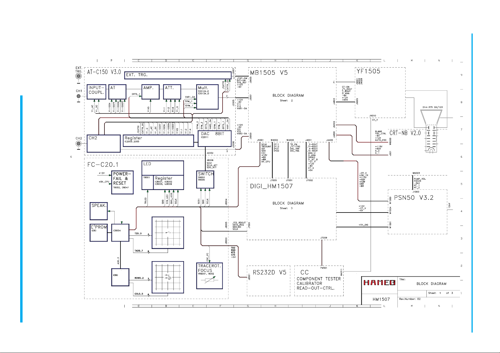
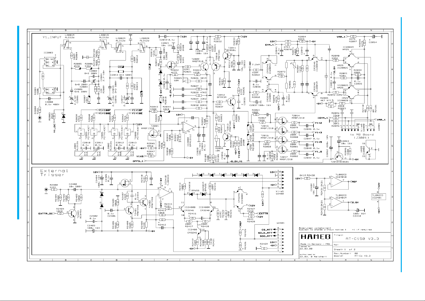
The 150 MHz Analog-/Digital-Oscilloscope HM1507-3 (200MSa/s)
Autoset
Auto Cursor
Readout / Cursor
Save / Recall
2 Reference Memories
Dual Time Base
Component Tester
1kHz/1MHz Calibrator
RS232 Interface
Digital:
IRefresh, Single, Roll-, Envelope-, Average-,XY-Mode
IMax. Sampling Rate 200MSa/s, Storage 2x2048x8 bit
ITime Base A: 100s - 50ns/div., B: 20ms - 50ns/div.
IPre Trigger 25-50-75-100%, Post Trigger 25-50-75%
IScreen Refresh 180/s, Dot Join (linear)
Analog:
I2 x DC to 150MHz, 2 x 1mV-50V/div
ITime Base A with Trig. DC to 250MHz
ITime Base B with 2ndTrig. to 250MHz
ITrig. DC to 250MHz, TV Sync. Separator
I1kHz/1MHz Calibrator, CRT with 14kV
Specifications
Vertical Deflection
Operating modes: Channel I or II separate
both Channels (alternated or chopped)
Chopper frequency: approx. 0.5MHz)
Sum or Difference: from CH I and CH II
Invert: CH I and CH II
XY-Mode: via channel I (Y) and channel II(X)
Frequency range: DC to 150MHz (-3dB)
Rise time: <2.3ns
Overshoot: ≤1%
Deflection coefficient: 14 calibrated positions
from 1mV/div to 20V/div in 1-2-5 sequence,
variable 2.5:1 to min. 50V/div.
Accuracy in calibrated positions
1mV/div – 2mV/div: ±5%(DC-10MHz(-3dB))
5mV/div – 20V/div: ±3%
Input impedance: 1MΩII 15pF
Input coupling: DC-AC-GD (ground)
Input voltage: max. 400V (DC + peak AC)
Delay line: approx. 70ns
Triggering
Automatic (peak to peak):20Hz-250MHz (≥0.5div.)
Normal with level control:DC-250MHz (≥0.5div.)
Indicator for trigger action: LED
Slope: positive or negative
Sources: Channel I or II, line and external
ALT. Triggering: CH I/CH II (≥0.8div.)
Coupling: AC (10 – 250MHz)
DC (0 – 250MHz)
HF (50kHz – 250MHz)
LF (0 – 1.5kHz)
NR (Noise reject)0 - 50MHz (≥0.8div.)
Triggering time base B:normal with level control
and slope selection (0 – 250 MHz)
External: ≥0.3Vpp (0 – 250MHz)
Active TV Sync. Separator: field & line, + / –
Horizontal Deflection
Analog Time Base:
Accuracy in calibr. position 3%; 1-2-5 sequence
A: 0.5s-50ns/div.
B: 20ms-50ns/div.
Operating modes: A or B, alternate A/B
Variable: 2.5:1 up to 1.25s/div.
X-MAG. x10 (±5%) max. 5ns/div.
Holdoff time: variable to approx. 10:1
Bandwidth X-amplifier: 0 – 3MHz (-3dB)
X-Y phase shift: <3° below 220kHz
Digital Time Base:
Accuracy: 3%; 1-2-5 sequence
A: 100s-0.1µs/div.
Peak detect: 100s – 5µs/div.
B: 20ms-0.1µs/div.
Peak detect: 20ms – 5µs/div.
Operating modes: A or B, alternate A/B
X-MAG. x10 (±5%): 10ns/div.
Bandwidth X-Amplifier: 0 – 20MHz (-3dB)
X-Y phase shift: <3° below 20MHz
Input X-amplifier: via Channel II
Sensitivity: see CH II
Digital Storage
Operating modes: Refresh, Roll, Single, XY
Peak Detect, Average (2 to 512), Envelope
Dot Join function: automatically
Acquisition (real time)
8 bit flash A/D max. 200MSa/s
Peak detect: 5ns
Display refresh rate: max. 180/s
Memory & display: 2k x 8bit per channel
Reference memory: 2 waveforms 2k x 8bit
Saved in: (EEPROM).
Resolution (samples/div.): X 200/div.
Y25 /div.
XY 25 x 25/div.
Pre-/Post Trigger: 25,50,75,100, -25,-50,-75%
Operation / Control
Manual: front panel switches
Auto Set: signal related automatic
parameter selection
Save & Recall:9 user defined parameter settings
Readout & Cursor (analog/digital)
Display of parameter settings and other functions
on the screen. Trigger point indication.
Cursor measurement of ∆U, ∆t or 1/∆t (frequency),
separate or in tracking mode.
Readout intensity: separately adjustable.
Interface
PC remote control: built in RS232 interface
Option: HO79-6 Multifunction-Interface
IEEE-Bus, RS232, and Centronics
Output formats (HO79-6):PCL, Post Script
HPGL, EPSON
Opto interface HZ70
Component Tester
Test voltage: max. 7Vrms (o/c).
Test current: max. 7mArms (s/c)
Test frequency: approx.50Hz
One test lead is grounded (Safety Earth)
General Information
CRT: D14-375GY, 8x10cm internal graticule
Acceleration voltage: approx. 14kV
Trace rotation: adjustable on front panel
Calibrator: 0.2V ±1%, ≈1kHz/1MHz (tr <4ns)
Line voltage: 100-240V AC ±10%, 50/60Hz
Power consumption: approx. 47 Watt at 50Hz
Min./Max. ambient temperature: 0°C...+40°C
Protective system: Safety class I (IEC1010-1)
Weight: approx. 6.5kg (12.4lbs)
Color: techno-brown
Cabinet: W 285, H125, D380 mm
Lockable tilt handle 7/00
Accessories supplied: Operators Manual and PC software on CD-ROM, 4 Disks, Line Cord, 2 Probes 10:1
A
3
V
v
A
»
1
4
I:
|i
*1
f
|
|[p
*•..
i
isii
*-•
«
:g
.
2
8*1
III
Jj
l:
(jl
W*
{&]
hi
uti;
a.
•
.itH
.i1*1
w
1
1
:
Ilf
I
*
N
I