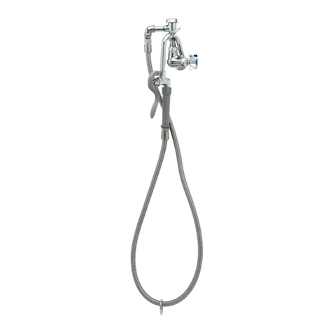
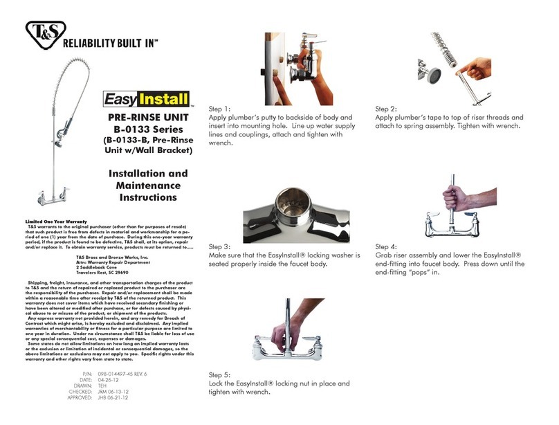
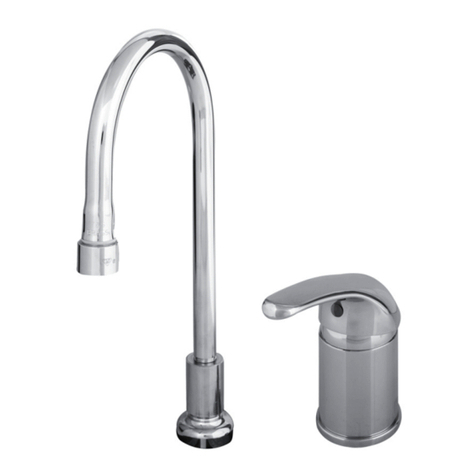
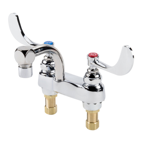
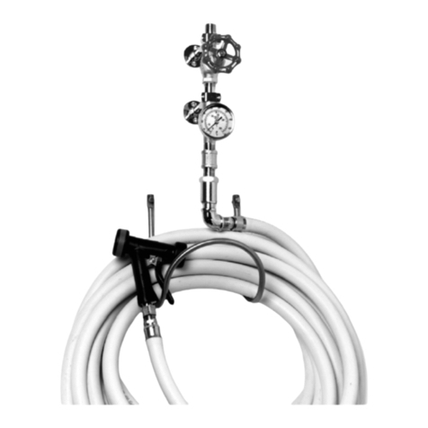
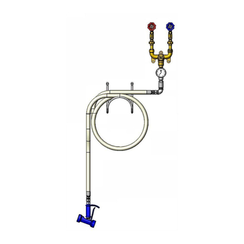
T&S B-0182 User manual

Installationand
Maintenance
Instructions
KETTLE KADDY
B-0182, B-0183, B-0186, B-0187,
B-0188, B-0192, B-0193
Deutsch: Installations-und
Wartungsanleitungen
Español: la Instalación y las
Instruccionesde
Mantenimiento
Français: lesInstructions
d’Installation et
d’Entretien
Limited One Year Warranty
T&Swarrantstotheoriginalpurchaser(otherthan
forpurposesofresale)thatsuchproductisfreefrom
defectsinmaterialandworkmanshipforaperiodof
one(1)yearfromthedateofpurchase. Duringthis
one-yearwarrantyperiod, iftheproductis foundto
bedefective,T&S shall,at itsoptions, repairand/
orreplaceit. Toobtainwarrantyservice,products
mustbereturnedto...
T&SBrassandBronzeWorks,Inc.
Attn: WarrantyRepairDepartment
2SaddlebackCove
TravelersRest,SC 29690
Shipping,freight,insurance,andothertranspor-
tationchargesoftheproducttoT&Sandthereturn
ofrepairedorreplacedproducttothepurchaserare
theresponsibilityofthepurchaser. Repairand/or
replacementshallbemadewithinareasonabletime
afterreceiptbyT&Softhereturned product. This
warrantydoesnotcoverItemswhichhavereceived
secondaryfinishingorhavebeenalteredormodi-
fiedafterpurchase, orfordefectscausedbyphysi-
calabuseto ormisuseoftheproduct,orshipment
oftheproducts.
Anyexpresswarrantynotprovidedherein,and
anyremedyforBreachofContractwhichmightarise,
is hereby excluded and disclaimed. Any implied
warrantiesofmerchantabilityorfitnessforaparticu-
larpurposearelimitedtooneyearinduration. Under
no circumstances shall T&S be liable for loss of
useor anyspecialconsequentialcosts,expenses
ordamages.
Somestatesdonotallowlimitationsonhowlong
andimpliedwarrantylastsortheexclusionorlimi-
tationof incidentalorconsequentialdamages,so
theabovelimitationsorexclusionsmay not apply
toyou. Specificrightsunderthiswarrantyandother
rightsvaryfromstatetostate.
P/N: 098-003156-45 Rev.3
Date: 980707
Drawn: CW
Checked: MAB 10-16-98
Approved: MW 10-15-98

Exploded View
Stanchion Unit
*Some items are listed for instructional purposes
and may not be sold as separate parts.

Part Number Guide
Stanchion Unit
1Asm, Stanchion 002847-40
2Tube, Stanchion *
3Shield, Expansion 001411-45
4Bolt, Shield *
5Valve, Check - 1/2 001332-45
6Cap, B-0182, B-0183, B-0187, B-0188 001251-40
7Cap, B-0186 001250-40
8Cap, B-0192, B-0193 001252-40
9Riser 001561-25
10 Locknut 001801-20
11 Grease Tube *

Exploded View
Kettle Kaddy B-0182, B-0183, B-0187, B-0188
*Some items are listed for instructional purposes
and may not be sold as separate parts.

Part Number Guide
Kettle Kaddy Assembly B-0182
1Asm, Valve 002901-40
2Flange, Cap 1/2 NPSL 001457-40
3Mixing Yoke, "H" B-0182 000174-40
Mixing Yoke, "Y" B-0192 000175-40
4Nipple, Close 1/2 NPT 002533-25
5Swivel Body, 1/2" Pre-Rinse 000592-25
6Swivel Body, 1/2" 000590-25
7Asm, Nozzle - Double Jointed 18" 002848-40
8Nut, Swivel *
9Washer, Swivel 009538-45
10 Repair Kit (Not Included) #11 & #12 011643-45
11 Sleeve, Swivel 011429-45
12 O-Ring, Swivel Piece 001074-45
13 Asm, Vacuum Breaker Unit B-0183 002849-40
14 Asm, Vacuum Breaker 3/8 005256-40
15 Adapter, 3/8 MA x 3/4-14 MA 000545-25
16 Asm, Swivel Unit B-0187 002850-40
Ball Fitting PLN 5/8-27 Threaded *
17 Adapter, GN End x 3/4-14 MA 000552-25
18 Nut, Hex, Swivel Pre-Rinse 000735-40
19 Stem, Swivel Pre-Rinse 000839-25
20 O-Ring, Swivel Piece 001074-45
Flex Hose & Spray Assembly
21 Asm, Flex S/S Hose 104" B-0104-C
Asm, Flex S/S Hose 68" B-0068-C
22 Asm, Spray Valve B-0182 002853-40
23 Asm, Spry Vlv & Hook Nozzle B-0187 002851-40
31 Washer, #27 010476-45
Hook & Bolt Assembly
24 Asm, Hook & Bolt 002852-40
25 Nut, Acorn 000950-25
26 Washer, Hook 000975-25
27 Hook, Finger 4R 000021-40
28 Nut, Finger Hook Spacer 000705-40
29 Bolt, Finger Hook 001578-20
30 Screw, Finger Hook 000916-45

Kettle Kaddy B-0192 and B-0193
Exploded View
*Some items are listed for instructional purposes
and may not be sold as separate parts.

Part Number Guide
Kettle Kaddy Assembly B-0192
1Asm, Valve 002901-40
2Flange, Cap 1/2 NPSL 001457-40
3Mixing Yoke, "Y" B-0182 000175-40
4Nipple, Close 1/2 NPT 002533-25
5Swivel Body, 1/2" Pre-Rinse 000592-25
6Asm, VB Nozzle B-0193 002854-40
Asm, Swivel Unit B-0192 002855-40
7Nut, Hex, Swivel Pre-Rinse 000735-40
8Stem, Swivel Pre-Rinse 000839-25
9O-Ring, Swivel Piece 001074-45
10 Tee Stem *
11 Adapter, 3/8 MA x 3/4-14 MA 000545-25
12 Asm, Vacuum Breaker, 3/8 B-0193 005256-40
13 Nipple, Close 3/8 NPT 002535-25
Flex Hose & Spray Assembly
14 Asm, Flex S/S Hose 104" B-0104-C
15 Asm, Spray Valve B-0192 002853-40
16 Asm, Flex S/S Hose 68" B-0068-C
17 Asm, Spray Vlv & Hook Nzl B-0182 002851-40
18 #27 Washer 010476-45
Hook & Bolt Assembly
19 Asm, Hook & Bolt 002852-40
20 Nut, Acorn 000950-25
21 Washer, Hook 000975-25
22 Hook, Finger 4R 000021-40
23 Nut, Finger Hook Spacer 000705-40
24 Bolt, Finger Hook 001578-20
25 Screw, Finger Hook 000916-45

General Instructions
Installation:StanchionUnit
1. Shut off water supply and drain
lines. Prepare (2) two½” IPS (Iron
Pipe Size) nipples extending 6”[15cm]
above the floor, roughed into con-
crete. Apply Teflon Tape or pipe joint
compound to threads.
6”[15cm]
floor
nipple
2”
[5cm]
2. Screw no.5onto floor nipples. Be sure
to install with arrows pointing up. Apply
Teflon Tape or pipe joint compound to
threaded ends.
4. Screw no.9into each no.5with
running threads up.
5. Remove no.10 from top of no.9.
6. Slide no.1cover over assembly
and put no.6(or no.7or no.8) in
place to make certain no.9is centered
thru holes in no.6.
3.Unscrew flange caps frombottom
end of no.9. Apply Teflon Tape or
pipe joint compound to threads of
no.9.
7. Mark floor for no.1drillinglocations
while no.1,no.2and no.6is on.
8.Remove no.1,no.2and no.6and drill
(3) three 7/8"[2 cm] Ø holes into floor,
2-1/2"[6 cm] deep. Insert no.3.
9. Replace no.1and no.2without no.6.
Screw (2) two no.10’s down on each
no.9. Adjust each pair of no.10’s so
they are flush with the top of no.2and
jammed together.
10. Place no.6 overno.2.Attach
flange caps to no.6and tighten.
3
9
5
4
10
flange
cap
flange
cap
9
6
910
Item no.4to be attached to floor
only after final test for leaks has
beencompleted.

General Instructions
10. Insert no.29 through bottom hole
of no.6, screw on no.28 at top of
no.6, place no.27 onto no.28. No.26
goes onto no.27, then screw no.25
onto no.29 and tighten. Position
no.27 as desired. Tighten no.30 as
needed.
26
30
25
27
28
29
Installation: Kettle Kaddy
Assembly
11. Remove (no.3) yokefrom no.1
valves by unscrewing each coupling
nut from the yoke.
Note: Hook and bolt installation
will be similar on other units.
Note:Useitem numbers from
B-0182 exploded view.
Other models are similar.
12.ApplyTeflon Tape or pipe joint
compound to threads of no.9. Place
no.1onto no.9 as far as it will go.
6
coupling
nut
5
3
9
1
1
13.Remove spindleassembly from
the second no.1, screw valve onto
other no.9.
1spindle
assembly
14. Replace spindleassembly onto
no.1body.
15. Replace no.3on both no.1
couplings and tighten with a wrench.
16.Attach no.7to no.6.
17.Attach no.21 to no.5.
721
5
6
3
1
18.Turn on
water and check
for leaks.
Installation: Hook and Bolt
Assembly

Instruccione
Generales
Instalación:UnidadDePuntal
1. Cierre la fuente de agua y desagüe las
tuberias. Perfore (2) dos tubos de 1/2” IPS
(Tamaño De Tubo Hierro) extendiendo
15 cm sobre el piso, aproximadamente en
el concreto. Aplique cinta de Teflon ó
compuesto de coyuntura a las roscas.
[15cm]
tubo del
piso
[5cm]
2. Atornille la parte No.5en los tubos del
piso. Este seguro de instalar con las
flechas señalando hacia arriba. Aplique
cinta de Teflon ó compuesto de coyuntura
a las extremidades enroscadas.
4. Atornille las partes No.9a dentro de
cada parte No.5con las roscas largas
hacia arriba.
5. Remuéva la parte No.10 sobre la parte
No.9.
6. Deslice el cubre parte No.1sobre el
ensamble y ponga la parte No.6(ó No.7
ó No.8) en sitio para asegurar que la
parte No.9este centrada a través de los
huecos en la parte No.6.
3. Destornille las tapas del reborde del
extremo inferior de la parte No.9.
Aplique cinta de Teflon ó compuesto de
coyuntura a las roscas de la parte No.9.
7. Indique el piso para la localización de
los huecos de la parte No.1mientras que
esten encima las partes No.1, No.2 y No.6.
8. Remuéva las parte No.1, No.2y No.6y
perfore (3) tres huecos de 2 cm Ø en el
piso, 6 cm de profundo. Insarte las partes
No.3.
9. Coloque de nuevo las partes No.1y
No.2sin la parte No.6. Atornille (2) dos
parte No.10 en cada parte No.9. Ajuste
cada par de partes No.10 a medida que
esten rás con la parte de arriba de la parte
No.2 y atranque ambas.
10. Coloque la parte No.6sobre la parte
No.2. Junte las tapas de reborde a la parte
No.6y aprete.
3
9
5
4
10
tapas del
reborde
tapas del
reborde
9
6
9
10
El artículo No.4será pegado al piso
solamente después de que se haya
completado la inspeccion final para
filtraciones.

Instruccione
Generales
10. Insarte la parte No.29 a través del hueco
inferior de la parte No.6, atornille la parte
No.28 sobre la parte No.6, coloque la parte
No.27 en la parte No.28. La parte No.26 va
en la parte No.27, luego atornille la parte
No.25 en la parte No.29 y aprete. Posicione
la parte No.27 a su deseo. Aprete la parte
No.30 como sea necesitado.
26
30
25
27
28
29
Instalación:EnsambleDelKettle
Kaddy
11. Remuéva (No.3) yugo de las valvulas
parte No.1destornillando cada tuerca de
enganche de el yugo.
Nota: La instalación de el gancho y
el tornillo será semejantes en otras
unidades.
Nota: Use los numeros de los
articulos del dibujo ampliado
B-0182. Otros modelos son
semejantes.
12. Aplique cinta de Teflon ó compuesto
de coyuntura a las roscas de la parte
No.9. Coloque la parte No.1dentro de la
parte No.9hasta su máximo trayecto.
6
Tuerca de
enganche
5
3
9
1
1
13. Remuéva el ensamble de eje del
segundo No.1, atornille la válvula en la
otra parte No.9.
1
ensamble
de eje
14. Coloque de nuevo el ensamble de eje
en el cuerpo de la parte No.1.
15. Coloque de nuevo la parte No.3en
ambos tuercas de enganche parte No.1y
aprete con una llave.
16. Junte la parte No.7a la parte No.6.
17. Junte la arte No.21 a la parte No.5.
18. Abra el agua e inspeccione por
filtraciones.
721
5
6
3
1
Instalación:GanchoyEnsambleDe
Tornillo

Instructions
Générales
L’Installation : L’élément
Stanchion
1. Fermer la réserve de l’eau et égoutter la
tuyauterie. Préparer(2) deux 1/2” IPS (en
Angalais “Iron Pipe Size” en Français la
taille des tuyaux en fer) raccords à
l’hauteur de 15cm au-dessus du plancher,
déjà en béton. Appliquer le ruban en
Téflon ou le composé pour les tuyaux aux
filets.
[15cm] le
raccord du
plancher
[5cm]
2. Visser Nº.5sur les raccords du plancher;
Soyez certain que les flèches indiquer le
haut. Appliquer le ruban en Téflon ou le
composé pour les tuyaux aux extrémités
avec les filets.
4. Visser Nº.9dans chaque Nº.5avec le
filets courants vers le haut.
5. Enlever Nº.10 du haut de Nº.9.
6. Faire glisser la couverture sur
l’assemblage et mettre Nº.6(ou Nº.7ou
Nº.8) à sa place pour vérifier que Nº.9
être au centre à travers les trous dans
Nº.6.
3. Dévisser les capsules de la bride de
l’extrémité du fond de Nº.9. Appliquer le
ruban en Téflon ou le composé aux filets
de Nº.9.
7. Marquer le plancher pour l’emplacement
pour percer pendant Nº.1, Nº.2et Nº.6être
à ses places.
8. Enlever Nº.1, Nº.2et Nº.6et percer (3)
trois trous avec un diamètre 2cm dans le
plancher et 6cm profonde. Insérer Nº.3.
9. Remplacer Nº.1et Nº.2sans Nº.6.
Visser (2) deux Nº.10’s sur chaque Nº.9.
Régler chaque paire de Nº10’s jusqu’elles
sont au même niveau que le haut de Nº.2et
elles enfoncer ensemble.
10. Mettre Nº.6sur Nº.2. Attacher les
capsules de la bride rt resserrer.
3
9
5
4
10
la capsule
de la bride
la capsule
de la bride
9
6
910
On pouvoir attacher Nº.4 au
plancher après on a terminé les essais
pour les fuites.

Instructions
Générales
10. Insérer Nº.29 à travers le trou au
fond de Nº.6., visser Nº.28 au haut de
Nº.6, mettre Nº.27 sur Nº.28.Nº.26
aller sur Nº.27, puis visser Nº.25 sur
Nº.29 et resserrer. Mettre Nº.27
comme désiré. Resserrer Nº.30
commenécessaire.
26
30
25
27
28
29
L’Installation: L’Assemblage
“Kettle Kaddy”
11. Enlever le (Nº.3)jougdes
soupapes Nº.1en dévissant chaque
écrou attelage du joug.
Noter: L’installation de l’agrafe
et le boulon être semblable des
autreséléments.
Noter: Utiliser les numéros de
B-0182 la vue agrandie. Les
autres modèles être semblables.
12.Appliquer leruban enTéflon ou
le composé pour les tuyaux aux
filets de Nº.9. Mettre Nº.1dans Nº.9
aussi loins que possible.
6
écrou
attelage
5
3
9
1
1
13.Enlever l’assemblage dela
brochedu deuxième Nº.1, visser la
soupape sur l’autre Nº.9.
1l’assemblage
de la broche
14. Remplacer l’assemblage de la
broche sur Nº.1.
15. Remplacer Nº.3sur les attelages
(tous les deux) de Nº.1et resserrer
avec une clef anglaise.
16.Attacher Nº.7àNº.6.
17.Attacher Nº.21 à Nº.5.
18.Recommencer l’eauet vérifiers’il
y a des fuites.
721
5
6
3
1
L’Installation : L’Assemblage
de L’Agrafe et Le Boulon

Allgemeine Anleitungen
Installation: Halterung
1. Wasserzulauf absperren und
Leitungen entleeren.Zwei 1,25cm
großeIPS-Nippel, die15 cm über den
Boden ragen, in Beton vorbereiten.
Teflonband oder oder Rohrdichtungs-
masse auf das Gewinde auftragen.
Nippel
[15cm] vom
Boden
[5cm]
2. Nr. 5in den Bodenippel
einschrauben. Sicherstellen, daß die
Pfeile nach oben zeigen. Teflonband
oder Rohrdichtungsmasse auf das
Gewindeauftragen.
4.Nr. 9in jedeNr. 5mitdem Gewinde
nach oben einschrauben.
5.Nr. 10vonNr. 9oben entfernen.
6. DieAbdeckung von Nr. 1über die
Garnitur schieben und Nr. 6(oder
Nr. 7oder Nr. 8) an die richtige Stelle
bringen, um sicherzustellen, daß Nr. 9
durch dieLöcher in Nr.6zentriert
sitzt.
3. Flanschkappen vom unteren Ende
von Nr. 9abschrauben. Teflonband
oder Rohrdichtungsmasse auf das
Gewinde von Nr. 9auftragen.
7.Aufdem Fußboden markieren, wo
die Löcher gebohrt werden sollen,
währendNr. 1,Nr. 2undNr. 6sichan
ihremPlatz befinden.
8.Nr. 1,Nr. 2undNr. 6entfernenund
drei2 cmgroße Löcher,die 6cmtief
sind, in den Boden bohren. Nr. 3
einfügen.
9.Nr. 1undNr. 2ohne Nr. 6wieder
einsetzen. Zwei Nr. 10 auf jede Nr. 9
aufschrauben. Jedes Paar Nr. 10 so
justieren, daß sie glatt an der
Oberfläche von Nr. 2anliegen und
zusammengeklemmtsind.
10. Nr. 6über Nr. 2legen.Die
Flanschkappen auf Nr. 6befestigen
undfestziehen.
3
9
5
4
10
Flansch-
kappe
Flansch-
kappe
9
6
910
Nr. 4 wird erst auf dem Boden befestigt,
nachdem der abschließende
Dichtigkeitstest durchgeführt worden ist.

Allgemeine Anleitungen
10.Nr. 29 durch das unterste Loch von
Nr. 6hindurchführen, Nr. 28obenauf
Nr. 6aufschrauben,Nr. 27 auf Nr. 28
fügen. Nr. 26 gehört auf Nr. 27, dann
Nr. 25 auf Nr. 29 aufschrauben und
festziehen. Nr. 27an die gewünschte
Stelle positionieren. Nr. 30 je nach
Bedarffestziehen.
26
30
25
27
28
29
Installation: Wasserkesselkasten
11. Joch (Nr. 3)von denVentilenNr. 1
durch Lösen jeder Kupplungsmutter
von dem Joch entfernen.
Anmerkung: Die Haken- und
Bolzengarnitur ist bei anderen
Einheitenähnlich.
Anmerkung: Die Zahlen von der
Darstellung in auseinandergezogener
AnordnungvonB-0182benutzen.
Andere Modelle sind ähnlich.
12.Teflonband oder Rohrdichtungs-
masse auf das Gewinde von Nr. 9
auftragen.Nr. 1so weit wie möglich
aufNr. 9aufsetzen.
6
Kupplungs-
mutter
5
3
9
1
1
13.Spindelgarnitur vonder zweiten
Nr. 1entfernen, Ventil auf die andere
Nr. 9aufschrauben.
1Spindelgarnitur
14.Spindelgarnitur wiederauf den
Rumpf von Nr. 1aufsetzen.
15.Nr. 3auf beiden Kupplungen Nr. 1
aufsetzen und mit
Schraubenschlüssel festziehen.
16.Nr. 7mit Nr.6verbinden.
17.Nr. 21 mit Nr.5verbinden.
721
5
6
3
1
18. Wasser
andrehen
und auf
Dichtigkeit
prüfen.
Installation: Haken- und
Bolzengarnitur

T&S BRASS AND BRONZE WORKS, INC.
A firm commitment to application-engineered plumbing products
2 Saddleback Cove, P.O. Box 1088, T & S Brass-Europe
Travelers Rest, SC 29690 ‘De Veenhoeve’
Phone: (864) 834-4102 Oude Nieuwveenseweg 84
Fax: (864) 834-3518 2441 CW Nieuwveen
RELATED T&S BRASS PRODUCT LINE
B-0190
Combination Kettle
Filler and Spray
Stanchion
B-0195
Kettle Filler with
Hook Hose
Stanchion

Pre-Rinse Spray Valve
Limited One Year Warranty
T&S warrants to the original purchaser (other
than for purposes of resale) that such product
is free from defects in material and workman-
ship for a period of one (1) year from the date
of purchase. During this one-year warranty
period, if the product is found to be defective,
T&S shall, at its options, repair and/or replace
it. To obtain warranty service, products must
be returned to…
T&S Brass and Bronze Works, Inc.
Attn: Warranty Repair Department
2 Saddleback Cove
Travelers Rest, SC 29690
Shipping, freight, insurance, and other
transportation charges of the product to T&S
and the return of repaired or replaced product
to the purchaser are the responsibility of the
purchaser. Repair and/or replacement shall be
made within a reasonable time after receipt by
T&S of the returned product. This warranty does
not cover Items which have received secondary
finishing or have been altered or modified after
purchase, or for defects caused by physical
abuse to or misuse of the product, or shipment
of the products.
Any express warranty not provided herein,
and any remedy for Breach of Contract which
might arise, is hereby excluded and disclaimed.
Any implied warranties of merchantability or
fitness for a particular purpose are limited to
one year in duration. Under no circumstances
shall T&S be liable for loss of use or any special
consequential costs, expenses or damages.
Some states do not allow limitations on
how long and implied warranty lasts or the
exclusion or limitation of incidental or conse-
quential damages, so the above limitations or
exclusions may not apply to you. Specific rights
under this warranty and other rights vary from
state to state.
P/N: 098-011027-45 Rev.9
Date: 03-22-12
Drawn: TEH
Checked: JRM 03-26-12
Approved: JHB 03-27-12
Installation and
Maintenance
Instructions
B-0107
B-0107-C
B-0107-J
B-10K
B-10K-C
B-10K-J
UK-0107
UK-10K
EB-0107
EB-0107-C
EB-0107-J
EB-10K
EB-10K-C
EB-10K-J

2
Exploded View
1
2
3
7
8
9
10
11
21
13
14
15
16
17
18
17
19
20
12
25
24
23
5
6
4
22

3
Grey
Grey Part Number Guide
PARTS FOR ANY GREY T&S SPRAY VALVE
1
2
3
4
5
6
Ring, Hold Down
#27 Washer
Body, Spray Valve
Grey Handle
Nut, Handle
Screw, Handle
000907-45
010476-45
000065-40
001120-45
003198-45
003199-45
7
8
9
10
11
22
23
24
22
23
24
25
B-0107 (1.42 GPM)
Nipple
Cup, Spray
Ring, Sprayhead
1.42 GPM Sprayface
Screw, Sprayface
B-0107-C (0.65 GPM)
Assembly, B-0107C Spray Nozzle
0.65 GPM Grey Shield (No Outline Around Lettering)
0.65 GPM Spray Nozzle (0.65 Stamped on Face)
B-0107-J (1.07 GPM)
Assembly, B-0107-J Spray Nozzle
1.07 GPM Grey Shield (Square Outline)
1.07 GPM Spray Nozzle (1.07 Stamped on Face)
Nozzle Holder
000694-40
000019-40
007861-45
001121-45
000913-45
002662-40
002659-45
N/A
N/A
018292-45
N/A
N/A
Bonnet Assembly
Stem
Washer, Seat
Washer, Bonnet Binding
Bonnet
Washer, Bonnet Brass
Stem, Packing
Spring, Bonnet
Push Button
Grease Pack
002856-40
009306-20
012915-45
001040-45
000608-25
000974-45
001100-45
000895-45
000753-25
012665-45
12
13
14
15
16
17
18
19
20
21
1,2,3
PARTS
KIT
1,2,3
1,2,3
1,2,3
1,2,3
1,2,3
1,2,3
1,2,3
PARTS FOR ANY GREY BONNET ASSEMBLY
GREY SPRAY VALVES
1
1
1
2
3
#1 Parts included in B-10K
#2 Parts included in B-10K-C
#3 Parts included in B-10K-J

4
Blue
Blue Part Number Guide
PARTS FOR ANY BLUE T&S SPRAY VALVE
1
2
3
4
5
6
Ring, Hold Down
#27 Washer
Body, Spray Valve
Blue Handle
Nut, Handle
Screw, Handle
000907-45
010476-45
000065-40
011454-45
003198-45
003199-45
7
8
9
11
10
10
22
23
24
22
23
24
25
EB-0107 & UK-0107 Only
Nipple
Cup, Spray
Ring, Sprayhead
Screw, Sprayface
EB-0107 (4-6 GPM)
4-6 GPM Sprayface (No Wording on Face)
UK-0107 (1.42 GPM)
1.42 GPM Sprayface (Flow Rate on Face)
EB-0107-C (0.65 GPM)
Assembly, EB-0107C Spray Nozzle
0.65 GPM Blue Shield (No Outline Around Lettering)
0.65 GPM Spray Nozzle (0.65 Stamped on Face)
EB-0107-J (1.07 GPM)
Assembly, EB-0107-J Spray Nozzle
1.07 GPM Blue Shield (Square Outline)
1.07 GPM Spray Nozzle (1.07 Stamped on Face)
Nozzle Holder
000694-40
000019-40
011475-45
000913-45
011456-45
017288-45
N/A
011499-45
N/A
N/A
018293-45
N/A
N/A
Bonnet Assembly
Stem
Washer, Seat
Washer, Bonnet Binding
Bonnet
Washer, Bonnet Brass
Quad Seal
Spring, Bonnet
Push Button
Grease Pack
010594-40
009306-20
010563-45
010565-45
000608-25
000974-45
014615-45
000895-45
000753-25
010573-45
12
13
14
15
16
17
18
19
20
21
4,5,6,7
PARTS
KIT
4,5,6,7
4,5,6,7
4,5,6,7
4,5,6,7
4,5,6,7
4,5,6,7
4,5,6,7
PARTS FOR ANY BLUE BONNET ASSEMBLY
BLUE SPRAY VALVES
4,7
4,7
4
7
5
6
#4 Parts included in EB-10K
#5 Parts included in EB-10K-C
#6 Parts included in EB-10K-J
#7 Parts included in UK-10K
This manual suits for next models
6
Table of contents
Languages:
Other T&S Plumbing Product manuals
T&S
T&S B-0870 Series User manual

T&S
T&S EasyInstall B-0113 Series User manual
T&S
T&S B-0679 User manual

T&S
T&S B-1255 User manual

T&S
T&S EVERSTEEL S-1200 Series User manual

T&S
T&S B-0131 User manual

T&S
T&S B-0133 Series User manual

T&S
T&S BR5PR2500 User manual

T&S
T&S EVERSTEEL S-0230 User manual

T&S
T&S B-0805 Series User manual

T&S
T&S EVERSTEEL S-1100 Series User manual

T&S
T&S 002824-40 User manual

T&S
T&S Equip 5EF-1D-WG User manual

T&S
T&S B-16-K User manual

T&S
T&S B-0580 User manual

T&S
T&S B-0291 Series User manual

T&S
T&S B-2250 User manual

T&S
T&S B-2701 Series User manual

T&S
T&S B-1200 Series User manual

T&S
T&S B-0695 User manual