manuals.online logo
Brands
  1. Home
  2. •
  3. Brands
  4. •
  5. TE Connectivity
  6. •
  7. Tools
  8. •
  9. TE Connectivity 2255143-1 User manual

TE Connectivity 2255143-1 User manual

1 of 4
© 2015 TE Connectivity family of companies
All Rights Reserved
*Trademark
TE Connectivity, TE connectivity (logo), and TE (logo) are trademarks. Other logos, product, and/or company names may be trademarks of their respective owners.
TOOLING ASSISTANCE CENTER
1-800-722-1111
PRODUCT INFORMATION
1-800-522-6752
This controlled document is subject to change.
For latest revision and Regional Customer Service,
visit our website at www.te.com.
Instruction Sheet
408-32129
13 MAR 15 Rev A1
Figure 1
1. INTRODUCTION
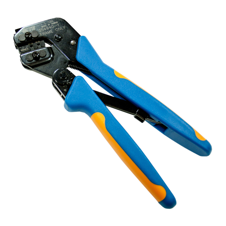
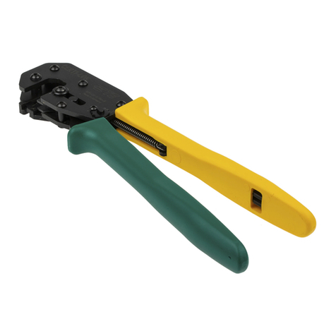
This instruction sheet covers the use of TE Connectivity Hand Crimping Straight Action Hand Tools (SAHT)
2255143-1 and 2255144-1 with flip locators which crimp D2000 Dynamic Series contacts listed in Figure 2.
NOTE
Dimensions are in metric units with [inches in brackets]. Figures and illustrations are for reference only and are not drawn to
scale.
Read these instructions thoroughly before crimping
any contacts.
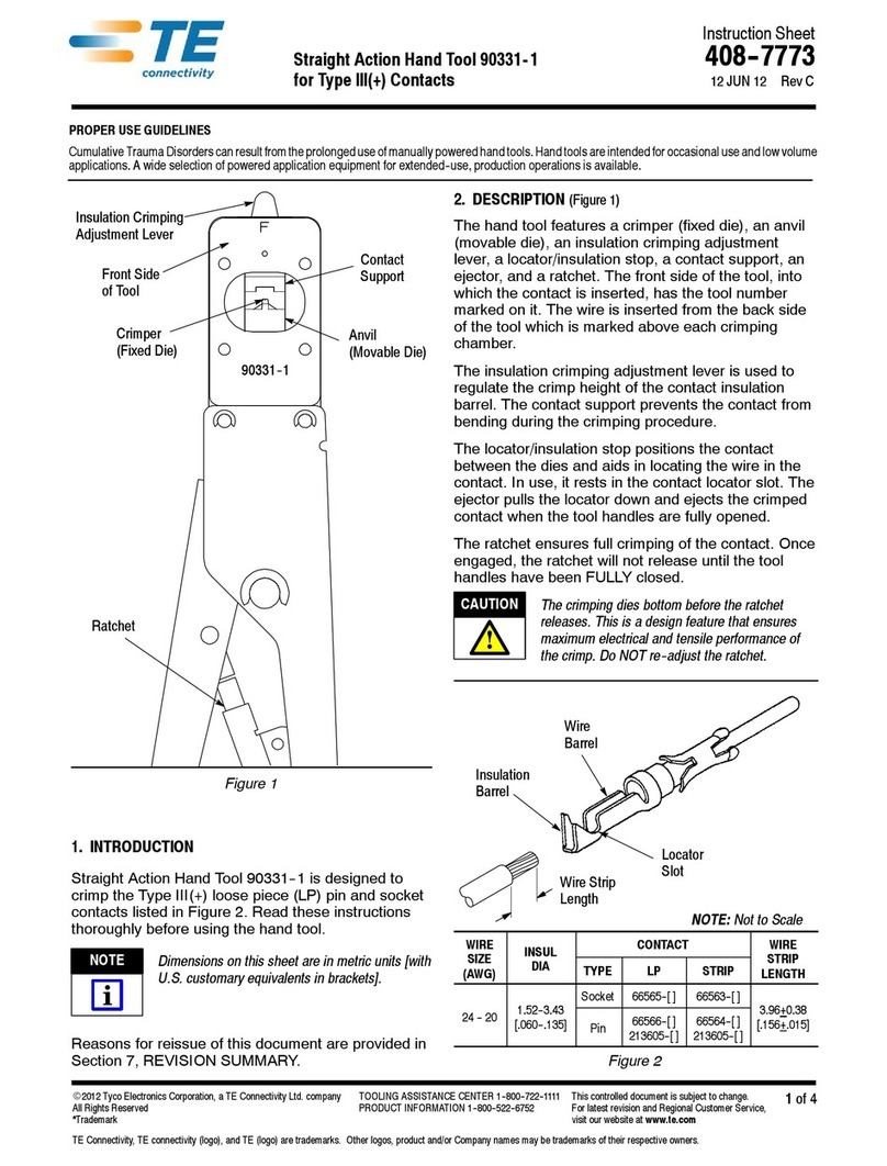
2. DESCRIPTION (Figure 1 and Figure 3)
The FRONT OF TOOL (contact side), is where the contact is inserted. The BACK OF TOOL (wire side), is
where the wire is inserted and has the wire size markings above each crimp section.
Each tool features a fixed die (crimper), a movable die (anvil), two crimp sections with applicable wire size
markings, a flip locator, a wire stop, and a ratchet release lever.
Once engaged, the ratchet will not release until the handles have been FULLY closed.
CAUTION
The ratchet ensures full crimping of the contact. This is a design feature that ensues maximum electrical and tensile
performance of the crimp. Do NOT readjust the ratchet.
The flip locator positions the contact in the crimping die, and the wire stop aids in locating the wire in the
contact. In use, it rests in the transition area of the connector. See Figure 1 and Figure 3
PROPER USE GUIDELINES
Cumulative Trauma Disorders can result from the prolonged use of manually powered hand tools. Hand tools are intended for occasional use and low
volume applications. A wide selection of powered application equipment for extended-use, production operations is available.
Mini Straight Action Hand Tools (SAHT)
2255143-1 and 2255144-1 with Flip Locators
For D2000 Dynamic Series Contacts
Crimper
Back of Tool
Ratchet
Anvil
NOTE: 2255143-1 is
Shown, but 2255144-1 is
Similar
00 0 0
ORIGINAL INSTRUCTIONS
408-32129
Rev A1
2 of 4
The flip locator prevents the contact from bending during the crimping procedure.
The ratchet release lever enables the user to open the partially closed tool handles when necessary.
The ratchet is used to control the crimp height of the terminal’s wire barrel and ensures full crimping of the
terminal.
The ratchet is used to control the crimp height of the terminal’s wire barrel and ensures full crimping of the
terminal.
Figure 2
3. CRIMPING PROCEDURE
Refer to the table in Figure 2 and ensure compatibility between the wire, contact, and crimping tool. Wire size
must be within the specified range for the contact. Strip the wire to the length indicated.
CAUTION
Do NOT cut or nick the wire strands.
The hand crimping tool must be the one designed for crimping the wire and contact. Identify the appropriate
crimp section (according to the wire size markings on the BACK of the tool).
Refer to Figure 3 and proceed as follows:
1. Hold tool so BACK (wire side) is facing you.
2. Make sure the ratchet is released by squeezing the tool handles and allowing them to open FULLY.
3. Open flip locator. Insert contact into the flip locator (make sure contact is inserted properly).
4. Close flip locator.
5. Pre-close the handles slightly, and insert the wire into the contact.
6. Close the handles until the automatic ratchet releases.
7. Open flip locator. Take wire with contact out of locator.
Wire Strip Length 2.9 to 3.9
[.114 to .153]
WIRE
SIZE
(AWG)
CONTACT
CRIMP
SECTION
(WIRE SIZE
MARKING)
HAND TOOL
28-26
S
1318108-1
1318112-1
28-26
2255143-1
24
24
22-20
M
1318107-1
1318111-1
22-20
2255144-1
18
18
408-32129
Rev A1
3 of 4
Figure 3
4. TOOL CERTIFICATION
These instructions have been approved by TE Design, Production, and Quality Control Engineers to provide
documented maintenance and inspection procedures.
Through TE test laboratories and the inspection of production assembly, the procedures described herein have
been established to ensure quality and reliability of TE hand crimping tools.
5. INSPECTION PROCEDURES
5.1. Daily Maintenance
It is recommended that each operator of the tool be made aware of, and responsible for, the following four
steps of daily maintenance:
1. Remove dust, moisture, and other contaminants with a clean brush, or a soft lint-free cloth. Do NOT
use objects that could damage the tool.
2. Make sure the proper retaining pins are in place and secured with the proper retaining rings.
3. Make certain all pins, pivot points, and bearing surfaces are protected with a THIN coat of any good
SAE No. 20 motor oil. Do NOT oil excessively.
4. When the tool is not is use, keep the handles closed to prevent objects from becoming lodged in the
crimping dies and store the tool in a clean dry area.
5.2. Periodic Inspection
Regular inspections should be performed by quality control personnel. A record of scheduled inspections
should remain with the tool and/or be supplied to supervisory personnel responsible for the tool. Through
recommendations call for at least one inspection a month, the inspection frequency should be based on the
amount of use, ambient working conditions, operator training and skill, and established company standards.
These inspections should be performed in the following sequence:
Visual Inspection
1. Remove all lubrication and accumulated film by immersing the tool (handles partially closed) in a
suitable commercial degreaser that will not affect paint or plastic material.
2. Make certain all retaining pins are in place and secured with retaining ring.
3. Close the tool handles until the ratchet releases, then allow handles to open freely. If they do not open
quickly and fully, return the tool to TE for evaluation and repair.
Flip Locator
408-32129
Rev A1
4 of 4
Inspect the head assembly with special emphasis on checking for worn, cracked, or broken die. If damage
to any part of the head assembly is evident, return the tool to TE for evaluation and repair.
Crimp Height Inspection
This inspection requires the use of a micrometer with a modified anvil as shown in Figure 4.
Proceed as follows:
Refer to the table in Figure 4 and select a contact and a wire (maximum size) for each crimp section listed
in the table.
1. Refer to Section 3, CRIMPING PROCEDURE and crimp the contact(s) accordingly.
2. Using a crimp height comparator, measure the wire barrel height as shown in Figure 4. If the crimp
height conforms to that shown in the table, the tool is considered dimensionally correct. If not, return
the tool to TE for evaluation and repair.
TE does not market crimp height comparators. Refer to Instruction Sheet 408-7424 for detailed
information on obtaining and using a crimp height comparator.
Figure 4
6. REVISION SUMMARY
Changed format.
HAND TOOL
CONTACT
CRIMP
SECTION
(WIRE SIZE
MARKING)
CRIMP HEIGHT
DIMENSION “A”
2255143-1
S
1318108-1
1318112-1
28-26 0.64 ±0.06
[.025 ±.002]
24
0.705 ±0.065
[.0277 ±.0025]
2255144-1
M
1318107-1
1318111-1
22-20 0.95 ±0.08
[.037 ±.003]
18
1.15 ±0.09
[.045 ±.003]

This manual suits for next models

1

Other TE Connectivity Tools manuals

TE Connectivity 734185-1 User manual

TE Connectivity

TE Connectivity 734185-1 User manual

TE Connectivity 58024-1 User manual

TE Connectivity

TE Connectivity 58024-1 User manual

TE Connectivity 2430769-1 User manual

TE Connectivity

TE Connectivity 2430769-1 User manual

TE Connectivity 90331- 1 User manual

TE Connectivity

TE Connectivity 90331- 1 User manual

TE Connectivity CERTI- LOK Hand Tool Frame Assembly 169400 User manual

TE Connectivity

TE Connectivity CERTI- LOK Hand Tool Frame Assembly 169400 User manual

TE Connectivity CXP 2018681-1 User manual

TE Connectivity

TE Connectivity CXP 2018681-1 User manual

TE Connectivity ERGOCRIMP 6-1579014-1 User manual

TE Connectivity

TE Connectivity ERGOCRIMP 6-1579014-1 User manual

TE Connectivity 1725062-1 User manual

TE Connectivity

TE Connectivity 1725062-1 User manual

TE Connectivity 768338-2 User manual

TE Connectivity

TE Connectivity 768338-2 User manual

TE Connectivity TERMI-POINT 59865-1 Reference guide

TE Connectivity

TE Connectivity TERMI-POINT 59865-1 Reference guide

TE Connectivity CERTI-CRIMP II Reference guide

TE Connectivity

TE Connectivity CERTI-CRIMP II Reference guide

TE Connectivity 354711-1 User manual

TE Connectivity

TE Connectivity 354711-1 User manual

TE Connectivity 58372- 1 User manual

TE Connectivity

TE Connectivity 58372- 1 User manual

TE Connectivity SDE-SA User manual

TE Connectivity

TE Connectivity SDE-SA User manual
TE Connectivity Ocean 1.0 User manual

TE Connectivity

TE Connectivity Ocean 1.0 User manual

TE Connectivity PRO-CRIMPER III User manual

TE Connectivity

TE Connectivity PRO-CRIMPER III User manual

TE Connectivity OCEAN 2.0 User manual

TE Connectivity

TE Connectivity OCEAN 2.0 User manual

TE Connectivity HT11K User manual

TE Connectivity

TE Connectivity HT11K User manual

TE Connectivity 2215038-1 User manual

TE Connectivity

TE Connectivity 2215038-1 User manual

TE Connectivity 2255140-1 User manual

TE Connectivity

TE Connectivity 2255140-1 User manual

TE Connectivity 2379255-1 User manual

TE Connectivity

TE Connectivity 2379255-1 User manual

TE Connectivity SDE-SA User manual

TE Connectivity

TE Connectivity SDE-SA User manual

Popular Tools manuals by other brands

Hakko Electronics 394-01 manual

Hakko Electronics

Hakko Electronics 394-01 manual

Matco Tools MT2816 operating instructions

Matco Tools

Matco Tools MT2816 operating instructions

CAPTELEC QUICK FIX instruction manual

CAPTELEC

CAPTELEC QUICK FIX instruction manual

Gage Bilt GB713SR-8 Original instructions

Gage Bilt

Gage Bilt GB713SR-8 Original instructions

BEA 554 DCC Spare parts list/service instructions

BEA

BEA 554 DCC Spare parts list/service instructions

TREND BS/JIG manual

TREND

TREND BS/JIG manual

Facom 14.9X12 instruction manual

Facom

Facom 14.9X12 instruction manual

Textron Greenlee Ultra Tugger 6800 Service manual

Textron

Textron Greenlee Ultra Tugger 6800 Service manual

SUHNER WB 4 Technical document

SUHNER

SUHNER WB 4 Technical document

Sears CRAFTSMAN 315.25710 owner's manual

Sears

Sears CRAFTSMAN 315.25710 owner's manual

NovoPress AFP101 operating manual

NovoPress

NovoPress AFP101 operating manual

ion science Hydrosteel 6000 user manual

ion science

ion science Hydrosteel 6000 user manual

DeWalt SDS MAX D25712 instruction manual

DeWalt

DeWalt SDS MAX D25712 instruction manual

Kreg KHI-PULL-INT owner's manual

Kreg

Kreg KHI-PULL-INT owner's manual

McElroy 1LC Operator's manual

McElroy

McElroy 1LC Operator's manual

Eskimo HD07 instruction sheet

Eskimo

Eskimo HD07 instruction sheet

Raider RD-AH01 user manual

Raider

Raider RD-AH01 user manual

Rockler 311373 instructions

Rockler

Rockler 311373 instructions

manuals.online logo
manuals.online logoBrands
  • About & Mission
  • Contact us
  • Privacy Policy
  • Terms and Conditions

Copyright 2025 Manuals.Online. All Rights Reserved.