manuals.online logo
Brands
  1. Home
  2. •
  3. Brands
  4. •
  5. TE Connectivity
  6. •
  7. Tools
  8. •
  9. TE Connectivity 58024-1 User manual

TE Connectivity 58024-1 User manual

Instruction Sheet
Manual Arbor Frame Assembly 408--6923
LOC B
1of 3
E2011 Tyco Electronics Corporation, a TE Connectivity Ltd. Company
All Rights Reserved
TE logo is a trademark.
*Trademark. Other product names, logos, or company names might be trademarks of their respective owners.
TOOLING ASSISTANCE CENTER 1--800--722--1111
PRODUCT INFORMATION 1--800--522--6752
This controlled document is subject to change.
For latest revision and Regional Customer Service,
visit our website at www.te.com
11 Mar 11 Rev D58024- 1
PROPER USE GUIDELINES
Cumulative Trauma Disorders can result from the prolonged use of manually powered hand tools. Hand tools are intended for occasional use and low volume
applications. A wide selection of powered application equipment for extended--use, production operations is available.
Figure 1
Frame Handle
Handle Adjusting Knob
Ram (Retracted)
Adjustment
Ring
Mounting Holes
(4 Places)
Base Plate
Setscrew
Plug Button
50.8 mm
[2 in.] (Ref)
1. INTRODUCTION
Manual Arbor Frame Assembly 58024--1, shown in
Figure 1, provides the necessary force to drive
various tooling assemblies (upper and lower tooling)
to be used for a specific purpose.
Dimensions in this instruction sheet are in
millimeters [with inches in brackets]. Figures are
not drawn to scale.
Reasons for reissue of this instruction sheet are
provided in Section 7, REVISION SUMMARY.
2. DESCRIPTION
The arbor frame assembly features a bench--
mountable frame, base plate, handle, handle
adjusting knob, adjustment ring, and ram. The handle
is adjustable for storage.
3. SETUP AND OPERATION
1. Grasp the handle, and loosen the handle
adjustment knob sufficiently for the handle to slide.
FULLY extend the handle. Tighten the knob,
making sure that the screw enters the last hole in
the handle.
2. Secure the arbor frame assembly to a
workbench to ensure stability during operation.
Refer to Figure 2 for mounting hole dimensions.
Figure 2
172.2 [6.78]
127 [5]
164.6 [6.48]
7.14 [.281]
Dia
Front of Arbor Frame Assembly
Mounting Hole Dimensions
NOTE
i
408- 6923
Rev D2 of 3
3. Secure the appropriate upper tooling to the ram
according to the instructions packaged with the
upper tooling.
4. Secure the appropriate lower tooling to the base
plate according to the instructions packaged with
the lower tooling.
5. To actuate the ram, pull down on the handle
until the upper tooling bottoms on the lower tooling.
To retract the ram, raise the handle.
Before beginning production, make sure that the
ram height is properly set according to Paragraph
4.1 and, if desired, adjust the handle according to
Paragraph 4.2.
4. ADJUSTMENTS
IMPORTANT: The ram height should be set before
adjusting the handle.
4.1. Ram Height Adjustment
After installing the tooling assembly, it might be
necessary to adjust the height of the ram. Adjust the
ram height as follows:
1. Determine the closed ram height dimension
required for the application.
2. Measure the distance between the bottom
surface of the upper tooling and the upper surface
of the lower tooling. Determine the direction (UP or
DOWN) that the ram must be moved.
3. Loosen the setscrew on the adjustment ring,
rotate the adjustment ring clockwise to increase
ram height, or counterclockwise to decrease ram
height, then tighten the setscrew. Continue making
adjustments until the proper closed ram height
dimension is attained.
4.2. Adjusting the Handle
To avoid personal injury when adjusting the
handle, STAY CLEAR OF THE HANDLE.
Depending on position, the weight of the ram
could force the handle to rotate quickly.
1. Using the tip of a small flat--blade screwdriver,
remove the plug button. Remove the socket head
cap screw and washer from the bore of the frame.
2. Grasp the adjustment ring, and pull the pinion
(small diameter gear in bore of frame) out of the
frame just enough to disengage it from the gear
teeth in the ram. Allow the ram to drop slowly until
the adjustment ring rests on the frame.
If the adjustment ring is NOT held in place when
the pinion is removed, the ram will drop and the
adjustment ring will slam onto the frame.
3. Rotate the handle to the desired position.
Ensure that the pinion rotates with the handle.
4. Push the pinion into the bore of the frame until it
engages the gear teeth in the ram.
5. Re--install the socket head cap screw and
washer. Re--install the plug button.
5. MAINTENANCE AND INSPECTION
5.1. Inspection
It is recommended that the arbor frame assembly be
inspected according to Figure 3 immediately upon
arrival at your facility (and at regularly scheduled
intervals thereafter) to ensure that it has not been
damaged during handling.
5.2. Lubrication
To prolong the useful life of the arbor frame assembly,
and to provide the smoothest operation, lubricate
monthly as follows:
Though recommendations call for lubrication at
least once a month, the frequency should be
based on amount of use, working conditions, and
established company policies.
1. Remove the upper tooling and lower tooling.
2. Move the ram to the bottom of its stroke (the
adjustment ring should bottom on the base plate).
Note the position of the handle. Loosen the handle
adjustment knob sufficiently for the handle to slide
from its mounting hole. Remove the handle.
3. Using a small flat--blade screwdriver, turn the
spring plunger (refer to Figure 3 for location)
counterclockwise until it no longer contacts the
ram.
4. Grip the adjustment ring, and pull it upward,
then remove the ram.
5. Apply ANDEROL 757 grease, or equivalent, to
the gear teeth on the ram and to the bore of the
frame.
6. Re--assemble the ram into the bore with the
grooved side of the ram aligned with the spring
plunger. Ensure that the gear teeth in the ram
engage the teeth of the pinion (small diameter gear
in bore of frame) so that the handle position will be
the same as noted in Step 2 when the adjustment
ring bottoms.
7. Turn the spring plunger clockwise until it
bottoms lightly on the ram, then back off one--half
of a turn.
NOTE
i
DANGER
CAUTION
!
NOTE
i
408- 6923
3of 3Rev D
8. Re--assemble the handle and upper tooling and
lower tooling. Ensure proper alignment of tooling
before operating the arbor frame assembly.
9. Remove any excess grease from the outer
surface of the frame and adjustment ring with a
soft cloth.
6. REPLACEMENT AND REPAIR
Customer--replaceable parts are listed in Figure 3.
A complete inventory should be stocked and
controlled to prevent lost time when replacement of
parts is necessary. Parts other than those listed
should be replaced by TE to ensure quality and
reliability. Order replacement parts through your
representative, or call 1--800--526--5142, or send a
facsimile of your purchase order to 717--986--7605, or
write to:
CUSTOMER SERVICE (038--035)
TYCO ELECTRONICS CORPORATION
PO BOX 3608
HARRISBURG PA 17105--3608
For customer repair service, contact a representative
at 1--800--526--5136.
7. REVISION SUMMARY
Revisions to this instruction sheet include:
SUpdated document to corporate requirements
1
2
3
45
67
193.7 [7.63]
254 [10]
241.3 [9.50]
Weight: 5.9kg[13lb]
REPLACEMENT PARTS
ITEM PART NUMBER DESCRIPTION QTY PER
ASSEMBLY
12--22484--1 BUTTON, Plug 1
227898--1 KNOB, Handle Adjusting 1
319120--1 GRIP, Handle 1
428053--2 PLUNGER, Spring 1
5311481--1 SHAFT, Handle 1
622736--6 SETSCREW, Socket 1
7311534--1 RING, Adjustment 1
Figure 3

Other TE Connectivity Tools manuals

TE Connectivity 734185-1 User manual

TE Connectivity

TE Connectivity 734185-1 User manual

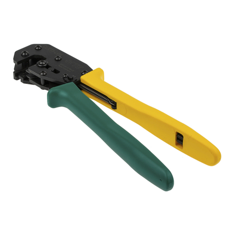
TE Connectivity PRO-CRIMPER III User manual

TE Connectivity

TE Connectivity PRO-CRIMPER III User manual

TE Connectivity 768338-2 User manual

TE Connectivity

TE Connectivity 768338-2 User manual

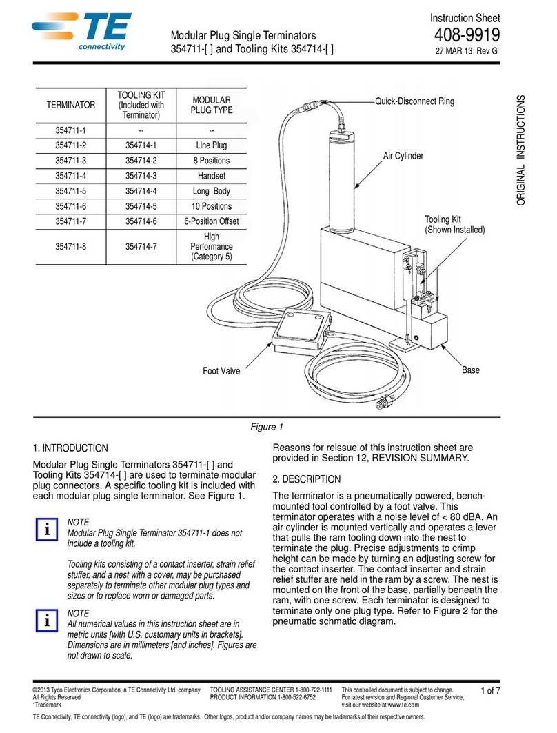
TE Connectivity 354711-1 User manual

TE Connectivity

TE Connectivity 354711-1 User manual

TE Connectivity 90331- 1 User manual

TE Connectivity

TE Connectivity 90331- 1 User manual

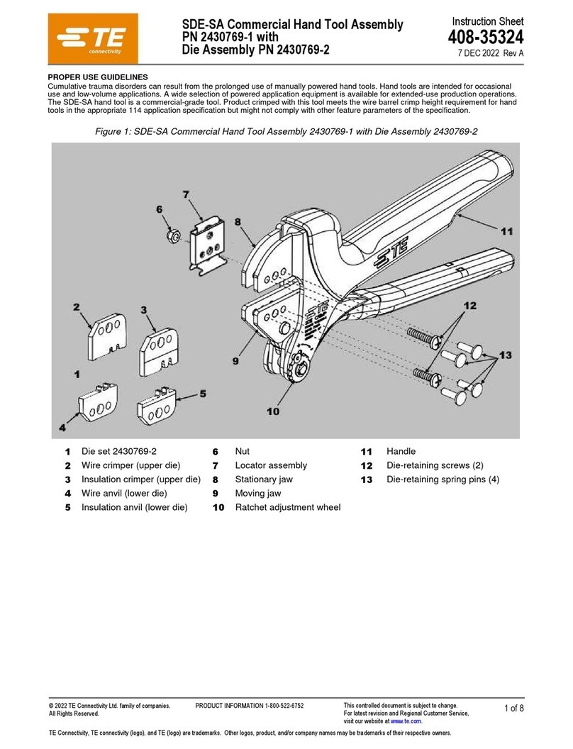
TE Connectivity SDE-SA User manual

TE Connectivity

TE Connectivity SDE-SA User manual

TE Connectivity ERGOCRIMP 6-1579014-1 User manual

TE Connectivity

TE Connectivity ERGOCRIMP 6-1579014-1 User manual

TE Connectivity 2379255-1 User manual

TE Connectivity

TE Connectivity 2379255-1 User manual

TE Connectivity CERTI- LOK Hand Tool Frame Assembly 169400 User manual

TE Connectivity

TE Connectivity CERTI- LOK Hand Tool Frame Assembly 169400 User manual

TE Connectivity 58372- 1 User manual

TE Connectivity

TE Connectivity 58372- 1 User manual

TE Connectivity SDE-SA User manual

TE Connectivity

TE Connectivity SDE-SA User manual

TE Connectivity Ocean 1.0 User manual

TE Connectivity

TE Connectivity Ocean 1.0 User manual

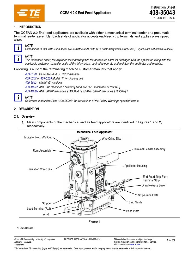
TE Connectivity OCEAN 2.0 User manual

TE Connectivity

TE Connectivity OCEAN 2.0 User manual

TE Connectivity 1725062-1 User manual

TE Connectivity

TE Connectivity 1725062-1 User manual

TE Connectivity 2215038-1 User manual

TE Connectivity

TE Connectivity 2215038-1 User manual

TE Connectivity 2430769-1 User manual

TE Connectivity

TE Connectivity 2430769-1 User manual

TE Connectivity HT11K User manual

TE Connectivity

TE Connectivity HT11K User manual

TE Connectivity TERMI-POINT 59865-1 Reference guide

TE Connectivity

TE Connectivity TERMI-POINT 59865-1 Reference guide

TE Connectivity 2255143-1 User manual

TE Connectivity

TE Connectivity 2255143-1 User manual

TE Connectivity 2255140-1 User manual

TE Connectivity

TE Connectivity 2255140-1 User manual

TE Connectivity CERTI-CRIMP II Reference guide

TE Connectivity

TE Connectivity CERTI-CRIMP II Reference guide

TE Connectivity CXP 2018681-1 User manual

TE Connectivity

TE Connectivity CXP 2018681-1 User manual

Popular Tools manuals by other brands

HEIDENHAIN 1070307-01 Mounting instructions

HEIDENHAIN

HEIDENHAIN 1070307-01 Mounting instructions

Bostitch BTFP12180 Operation and maintenance manual

Bostitch

Bostitch BTFP12180 Operation and maintenance manual

Sealey SJBEX200.V2 manual

Sealey

Sealey SJBEX200.V2 manual

Rohm EXTRA-RV Translation of the original operating manual

Rohm

Rohm EXTRA-RV Translation of the original operating manual

MATO Skiver S Directions

MATO

MATO Skiver S Directions

Honeywell r7284 Technicianís quick reference guide

Honeywell

Honeywell r7284 Technicianís quick reference guide

Hilti NPU 100 IP-A22 Original operating instructions

Hilti

Hilti NPU 100 IP-A22 Original operating instructions

Meridian HARVEST T852 Operator's manual

Meridian

Meridian HARVEST T852 Operator's manual

Metabo HPT M 18DYA manual

Metabo HPT

Metabo HPT M 18DYA manual

Fein 9 01 04 003 01 1 manual

Fein

Fein 9 01 04 003 01 1 manual

Planeta 808 Series Installation and operation manual

Planeta

Planeta 808 Series Installation and operation manual

BEA 180x50-786E Spare parts list/service instructions

BEA

BEA 180x50-786E Spare parts list/service instructions

Perel HGG400PRO user manual

Perel

Perel HGG400PRO user manual

Flexco Alligator Series Instructions for installation

Flexco

Flexco Alligator Series Instructions for installation

Bosch GNA 18V-16 Professional manual

Bosch

Bosch GNA 18V-16 Professional manual

Matco Tools BELT MASTER MESBT17 manual

Matco Tools

Matco Tools BELT MASTER MESBT17 manual

Fujikura CT08 instruction manual

Fujikura

Fujikura CT08 instruction manual

Nakanishi RA-200 Operation manual

Nakanishi

Nakanishi RA-200 Operation manual

manuals.online logo
manuals.online logoBrands
  • About & Mission
  • Contact us
  • Privacy Policy
  • Terms and Conditions

Copyright 2025 Manuals.Online. All Rights Reserved.