manuals.online logo
Brands
  1. Home
  2. •
  3. Brands
  4. •
  5. TE Connectivity
  6. •
  7. Tools
  8. •
  9. TE Connectivity 734185-1 User manual

TE Connectivity 734185-1 User manual

©2011 Tyco Electronics Corporation, Berwyn, PA
All Rights Reserved
TE logo and Tyco Electronics are trademarks.
*Trademark. Other products, logos, and company names might betrademarks of their respective owners.
Instruction Sheet
TOOLING ASSISTANCE CENTER 1-800-722-1111
PRODUCT INFORMATION 1-800-522-6752 This controlled document is subject to change.
For latest revision and Regional Customer Service,
visit our website at www.tycoelectronics.com
1of 3
LOC B
Wire Stripper 734185-1 408-8907
03 OCT 11 Rev B
Figure 1
1. INTRODUCTION
Wire Stripper 734185-1 is designed to strip wire sizes
28-10 AWG. Read these instructions thoroughly before
using the tool.
All dimensions on this document are in metric units
[with U.S. customary units in brackets].
2. DESCRIPTION
The tool, which has a retracting jaw type hand
operated wire stripper, automatically strips wire sizes
28-10 AWG with minor adjustments. Wire ends can be
stripped up to 16 mm [.625 in.].
3. WIRE CUTTING AND STRIPPING
Forproperoperationofthetool,jawsandinsulation
must be free of lubrication.
1. Insert wire into the cutting blades and squeeze
handles to cut. See Figure 1.
Keep fingers away from blades at all times.
2. To strip insulation, adjust the stripping blade
depth for the insulation thickness at the top of the
tool. Slide the insulation thickness adjustment
regulator as follows:
•Thin-Rear Position (toward handles)
•Normal-Center Position
•Thick-Forward Position
3. To adjust the strip length, move the wire stop by
squeezing the top tabs with fingers and sliding wire
stop to the desired measured wire length. Refer to
Figure 2.
Insulation Thickness
Adjustment Indicator
Upper
Stripping
Jaw
Front of
Tool
Lower
Stripping
Jaw Cutting
Blades
Wire
Stop
NOTE
i
NOTE
i
DANGER
STOP
ORIGINAL INSTRUCTIONS
408-8907
2of 3
Rev B
Figure 2
4. To strip wire, insert wire into front of tool until it
makes contact with the wire stop.
5. Squeeze handle firmly while holding wire
stationary.
6. Re-adjust the insulation thickness adjustment
regulator and wire stop if necessary.
4. MAINTENANCE AND INSPECTION
Wire Stripper 734185-1 requires no special
maintenance. After use, remove stripped wire and
check to ensure insulation slug has been ejected from
the jaws. Store tool in a clean, dry area.
If the stripping jaws are damaged, replace with Wire
Stripper Blade Assembly 1424946-1. See Figure 3.
For ordering information, refer to Section 6,
ORDERING INFORMATION / REPLACEMENT
PARTS.
Figure 3
5. REMOVAL / INSTALLATION OF REPLACEMENT JAWS
5.1. Jaw Removal (Figure 4 and Figure 5)
1. Open the jaws and position the tool as shown in
Figure 4.
2. Remove the wire stop by squeezing the top tabs
together and lifting the stop from the jaws.
3. Remove the upper stripping jaw by positioning a
screwdriver (on the label side of the tool) between
the tool housing and the jaw.
4. Rotate the screwdriver clockwise and disengage
the upper stripping jaw from the pivot.
5. Remove the upper stripping jaw and the spring.
6. Remove the lower stripping jaw by positioning a
screwdriver near the rear of the lower jaw. Using a
clockwise twisting motion, loosen and remove the
jaw from the pivot pin.
Figure 4
5.2. Jaw Installation (Figure 6)
1. Install the lower stripping jaw, with the pivot pin.
2. Position the spring into the throat of the lower
stripping jaw.
3. Position the upper stripping jaw, about 90_ to the
upper tool housing, with the pivot hole end towards
you.
WEAR SAFETY EYE PROTECTION when
installing the compressed spring as instructed in
Steps 4 through 6.
Wire Stop
(Adjustable)
Strip
Length
Wire
Pivot
Spring
Wire Stop
Strip
Blades
Wire
Stop
Upper
Stripping
Jaw
Pivot
DANGER
STOP
408-8907
3of 3
Rev B
Figure 5
4. Insert the spring into the upper stripping jaw by
bending it at an angle as shown in Figure 6.
5. While maintaining spring pressure, rotate the
upper stripping jaw pivot counterclockwise, and
engage the pivot pin.
6. Ensure that the upper stripping jaw is in proper
position in the tool housing.
7. Replace the wire stop.
6. ORDERING INFORMATION / REPLACEMENT PARTS
The only part that is replaceable is Wire Stripper Blade
Assembly 1424946-1. Order this part or additional wire
strippers through your TE Connectivity
Representative, or call 1-800-526-5142, or send a
facsimile of your purchase order to 717-986-7605, or
write to:
CUSTOMER SERVICE (038-035)
TYCO ELECTRONICS CORPORATION
PO BOX 3608
HARRISBURG PA 17105-3608
7. REVISION SUMMARY
•Deleted text in Section 2, DESCRIPTION
Figure 6
Upper
Stripping
Jaw
Screwdriver
Screwdriver
Lower
Stripping
Jaw
Top View
Side View
Upper Jaw
(About 90º to Tool)
Spring at
Angle
Pivot Pin

Other TE Connectivity Tools manuals

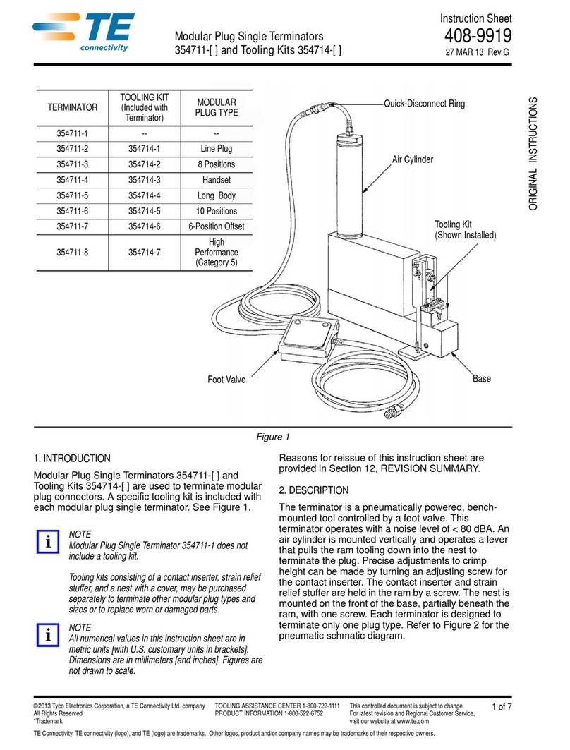
TE Connectivity 354711-1 User manual

TE Connectivity

TE Connectivity 354711-1 User manual

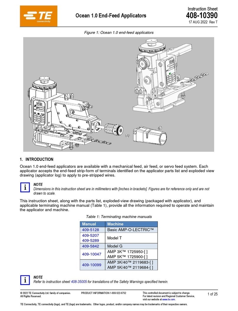
TE Connectivity Ocean 1.0 User manual

TE Connectivity

TE Connectivity Ocean 1.0 User manual

TE Connectivity 90331- 1 User manual

TE Connectivity

TE Connectivity 90331- 1 User manual

TE Connectivity TERMI-POINT 59865-1 Reference guide

TE Connectivity

TE Connectivity TERMI-POINT 59865-1 Reference guide

TE Connectivity 768338-2 User manual

TE Connectivity

TE Connectivity 768338-2 User manual

TE Connectivity CERTI- LOK Hand Tool Frame Assembly 169400 User manual

TE Connectivity

TE Connectivity CERTI- LOK Hand Tool Frame Assembly 169400 User manual

TE Connectivity PRO-CRIMPER III User manual

TE Connectivity

TE Connectivity PRO-CRIMPER III User manual

TE Connectivity 2215038-1 User manual

TE Connectivity

TE Connectivity 2215038-1 User manual

TE Connectivity SDE-SA User manual

TE Connectivity

TE Connectivity SDE-SA User manual

TE Connectivity HT11K User manual

TE Connectivity

TE Connectivity HT11K User manual

TE Connectivity 2379255-1 User manual

TE Connectivity

TE Connectivity 2379255-1 User manual

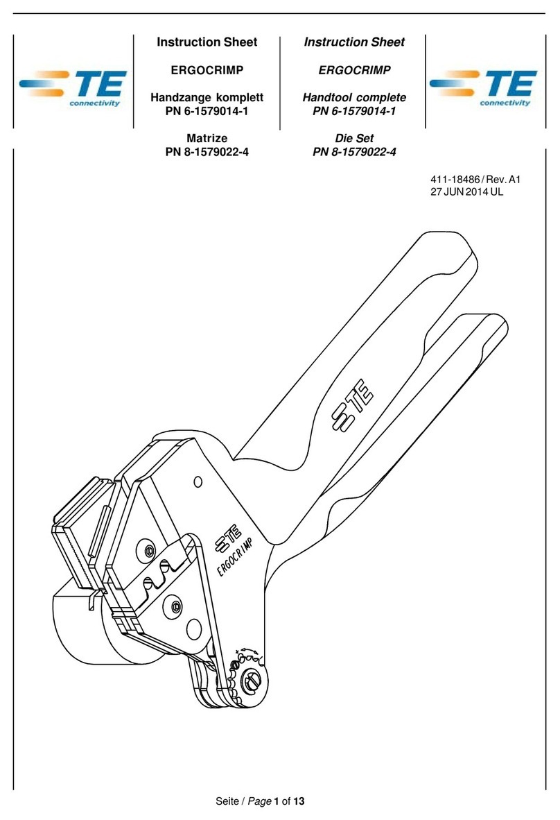
TE Connectivity ERGOCRIMP 6-1579014-1 User manual

TE Connectivity

TE Connectivity ERGOCRIMP 6-1579014-1 User manual

TE Connectivity 2255140-1 User manual

TE Connectivity

TE Connectivity 2255140-1 User manual

TE Connectivity 58372- 1 User manual

TE Connectivity

TE Connectivity 58372- 1 User manual

TE Connectivity 2255143-1 User manual

TE Connectivity

TE Connectivity 2255143-1 User manual

TE Connectivity OCEAN 2.0 User manual

TE Connectivity

TE Connectivity OCEAN 2.0 User manual

TE Connectivity CERTI-CRIMP II Reference guide

TE Connectivity

TE Connectivity CERTI-CRIMP II Reference guide

TE Connectivity 58024-1 User manual

TE Connectivity

TE Connectivity 58024-1 User manual
TE Connectivity 1725062-1 User manual

TE Connectivity

TE Connectivity 1725062-1 User manual

TE Connectivity 2430769-1 User manual

TE Connectivity

TE Connectivity 2430769-1 User manual

TE Connectivity CXP 2018681-1 User manual

TE Connectivity

TE Connectivity CXP 2018681-1 User manual

TE Connectivity SDE-SA User manual

TE Connectivity

TE Connectivity SDE-SA User manual
Popular Tools manuals by other brands

Bahco BCL40IB quick guide

Bahco

Bahco BCL40IB quick guide

Bostitch 750S4 manual

Bostitch

Bostitch 750S4 manual

YATO YT-17260 Original instructions

YATO

YATO YT-17260 Original instructions

Sealey AUTO SERVICE PS990.V2 instructions

Sealey

Sealey AUTO SERVICE PS990.V2 instructions

MSW MSW-OBG80B user manual

MSW

MSW MSW-OBG80B user manual

RED ROOSTER RRI-BA16BOA H19 manual

RED ROOSTER

RED ROOSTER RRI-BA16BOA H19 manual

BorMann BPL7600 manual

BorMann

BorMann BPL7600 manual

HammerSmith M29773 manual

HammerSmith

HammerSmith M29773 manual

LockTech AccuReader GM10 instructions

LockTech

LockTech AccuReader GM10 instructions

Costway NP10216 user manual

Costway

Costway NP10216 user manual

Eskimo StingRay S33Q8 Assembly instructions & parts explosions

Eskimo

Eskimo StingRay S33Q8 Assembly instructions & parts explosions

Toro 5 Operator's manual

Toro

Toro 5 Operator's manual

SIC U2W Series operating instructions

SIC

SIC U2W Series operating instructions

RAMSET RA54 Operator's safety & operating instruction manual

RAMSET

RAMSET RA54 Operator's safety & operating instruction manual

Tryton TMB1500K Operating	 instruction

Tryton

Tryton TMB1500K Operating instruction

Powerfix Profi 71825 translation of original operation manual

Powerfix Profi

Powerfix Profi 71825 translation of original operation manual

Sealey AK455.V2 instructions

Sealey

Sealey AK455.V2 instructions

gerardi Standart series instructions

gerardi

gerardi Standart series instructions

manuals.online logo
manuals.online logoBrands
  • About & Mission
  • Contact us
  • Privacy Policy
  • Terms and Conditions

Copyright 2025 Manuals.Online. All Rights Reserved.