manuals.online logo
Brands
  1. Home
  2. •
  3. Brands
  4. •
  5. TE Connectivity
  6. •
  7. Tools
  8. •
  9. TE Connectivity 768338-2 User manual

TE Connectivity 768338-2 User manual

Instruction Sheet
Base Assembly Universal 408--9875
LOC B
1of 4
E2011 Tyco Electronics Corporation, a TE Connectivity Ltd. Company
All Rights Reserved
TE Connectivity, TE connectivity (logo), and TE (logo) are trademarks.
*Trademark. Other logos, product and/or Company names may be trademarks of their respective owners.
TOOLI NG ASSISTANCE CENTER 1--800--722 -- 1111
PRODUCT INFORMATION 1--800--522--6752
This controlled document is subject to change.
For latest revision and Regional Customer Service,
visit our website at www.te.com
22 Mar 11 Rev AArbor Tool 768338- 2
Figure 1
AMPLIMITE* .050 Series
AMP--LATCH* Paddleboard
679235--1 (408--9892)
679176--1 (408--9928)
CONNECTOR
TYPES
CONNECTOR- SPECIFIC
KITS
MANUAL ARBOR
FRAME ASSEMBLY
91085--2
BASE
SLIDE BASE
OF FRAME
ASSEMBLY
(Ref)
CABLE
GUIDES
FLUTED
PLATE FRONT
GUARD
TOOL STOP
(Not Shown)
(Ref)
CABLE
CLAMP
CABLE
STOP
UPPER
TOOL
MOUNT
SLOT ON UPPER TOOL
MOUNT POSITIONED
TOWARD FRONT OF
FRAME ASSEMBLY
1. INTRODUCTION
These instructions cover installation, setup, and
termination procedures for Base Assembly Universal
Arbor Tool 768338--2. The universal arbor tool is used
with connector--specific kits (listed in Figure 1) to
terminate connectors onto .64 mm [.025 in.]
centerline ribbon cable. The tooling assemblies are
used in conjunction with Manual Arbor Frame
Assembly 91085--2 (see Figure 1) or Pneumatic
Auto--Cycle Unit 91112--3.
For information regarding the setup and operation of
the arbor frame assembly, refer to instruction sheet
408--7777 and 408--6732 for the auto--cycle unit.
Installation and setup procedures for the
connector--specific kits are available in 408--9928 (for
679176--1) and 408--9892 (for 679235--1).
Read these instructions (and other referenced
documents) thoroughly before terminating any
connectors.
Dimensions are in millimeters [followed by
inches in brackets].
2. DESCRIPTION (Figure 1)
The universal arbor tool consists of an upper tool
mount and a lower tooling assembly. The lower
tooling consists of a machined base, a fluted plate,
two cable guides, a cable clamp, a cable stop, and a
front guard. The machined base allows the tooling to
be moved into and out of the crimping area of the
arbor frame assembly. The fluted plate is designed to
provide proper seating of the ribbon cable. The cable
guides aid in positioning the ribbon cable with the
connector assembly, and the cable clamp holds the
NOTE
i
408- 9875
Rev A2 of 4
ribbon cable in position. The cable stop provides
proper positioning of the ribbon cable for flush
terminations.
3. INSTALLATION OF BASE ASSEMBLY UNIVERSAL
ARBOR TOOL (Figure 1)
The procedures in this section are typical for both
the Manual Arbor Frame Assembly and the
Pneumatic Auto--Cycle Unit.
Before installing the universal arbor tool in the
Pneumatic Auto--Cycle Unit, DISCONNECT air
from main air valve.
1. Secure upper tool mount to ram with the two
socket head cap screws.
The slot on the upper tool mount must face
toward the FRONT of the frame assembly, as
shown in Figure 1.
2. Remove tool stop from the front of the slide
base.
3. Position lower tooling assembly onto slide base
of frame assembly and slide into position.
4. Replace tool stop and tighten it to secure the
lower tooling assembly onto the slide base.
4. TERMINATION PROCEDURE
1. Install the connector--specific kit onto the
universal arbor tool; then set up the tooling
components for termination. Refer to the
instruction sheet supplied with the
connector--specific kit. See Figure 2.
Figure 2
NOTE: GUARD REMOVED FOR CLARITY
MANUAL ARBOR
FRAME ASSEMBLY
(Ref)
RAM
REAR TOOL
STOP
CABLE
GUIDES
CABLE POSITIONED IN FLUTES
OF FLUTED PLATE AND
BETWEEN CABLE GUIDES
CABLE CLAMP
CLOSED
LOWER
INSERT
CABLE
STOP
(Ref)
LOCATORS
AMPLIMITE PLUG
CONNECTOR
UPPER
TOOL
UPPER TOOL
MOUNT
(Ref)
TOOL HANDLE
NOTE
i
DANGER
NOTE
i
408- 9875
3of 4Rev A
To avoid personal injury, make sure all guards are
installed on the arbor frame assembly or
the auto--cycle unit before terminating the
connector.
2. Place cable into the flutes of the fluted plate, as
shown in Figure 2.
Cable conductors must stay in the same flutes for
the entire length of the fluted plate.
3. Insert connector into the lower insert using the
instructions supplied with the connector--specific
kit.
4. Slide cable through the connector so that the
end of the cable is against the cable stop. The
cable must be positioned between the cable
guides. When cable is properly positioned, close
the cable clamp. See Figure 2.
5. To actuate the ram for the arbor frame
assembly, slide lower tooling assembly toward rear
of base plate until it is positioned against the rear
tool stop. Pull down on the frame assembly handle
to terminate the cable to the connector.
To actuate the ram for the auto--cycle unit, slide
lower tooling assembly toward the rear of the
base plate until the sensing port closes. The
frame assembly will automatically cycle and
terminate the cable to the connector.
6. To retract the ram for the arbor frame assembly,
raise the tool handle. Slide tooling assembly out
from under the ram and remove the terminated
connector.
The ram will automatically retract when the
auto--cycle unit has completed the crimp cycle.
Slide the lower tooling out from under the ram to
remove the terminated connector.
7. Measure the termination height of the connector.
The dimension should conform to the termination
height dimensions provided in Application
Specification 114--40049. If the termination height
is incorrect, an adjustment to the ram height is
required. Refer to the instruction sheet supplied
with the appropriate frame assembly for ram height
adjustment procedures.
5. MAINTENANCE AND INSPECTION
5.1. Maintenance
Base Assembly Universal Arbor Tool 768338--2
requires little maintenance other than to keep it clean.
Remove debris and contaminants from the tooling
with a clean, soft, lint--free cloth or a clean, soft brush.
Do not use objects that could damage the tooling and
do not use any solvents that could harm paint or
plastic material. When not in use, store the tooling in
a clean, dry area.
5.2. Inspection
The tooling should be inspected immediately upon
arrival at your facility and at regularly--scheduled
intervals thereafter to ensure that it has not been
damaged. Examine the tooling for any signs of
damage or excessive wear during inspections. If
replacement of parts is necessary, refer to Figure 3
for the list of customer--replaceable parts.
6. REPLACEMENT AND REPAIR
Figure 3 provides a list of customer--replaceable parts
for the Base Assembly Universal Arbor Tool
768338--2. Replacement parts can be ordered
through your local TE Connectivity representative.
Parts replacement and tooling repair may also be
secured by calling the Product Information or the
Tooling Assistance Center at the numbers shown on
the bottom of the first page of this document.
7. REVISION HISTORY
Since the previous version of this document, the
following has been changed:
SUpdated document to corporate requirements.
DANGER
NOTE
i
NOTE
i
NOTE
i
408- 9875
Rev A4 of 4
223 12
24
25
24
22
27
910
28
12
26 4
21
17 18
910
14 15 20
19 13 11 16
BASE ASSEMBLY UNIVERSAL ARBOR TOOL 768338--2
ITEM PART NUMBER DESCRIPTION QUANTITY
2
4
9
10
11
12
13
14
15
16
17
18
19
20
21
22
23
24
25
26
27
28
768724--1
768599--1
27708--2
2--21000--0
23057--4
1--21000--9
1--21000--7
21055--7
2--21002--5
3--21028--4
1--21000--8
21055--5
314823--1
768602--1
768707--1
768915--1
768603--1
2--21006--7
679069--1
2--21000--3
679068--1
679070--1
PLATE, Fluted
BASE, Machined
KNOB, Thumbscrew, No. 6
SCREW, SHC, 6--32 x .50 LG
PLUNGER, Ball, SST
SCREW, SHC, 6--32 x .38 LG
SCREW, SHC, 4--4-- x .75 LG
WASHER, Flat, No. 10
SCREW, BHC, 10--32 x .25 LG
PIN, Roll, .093 x .38 LG
SCREW, SHC, 6--32 x .25 LG
WASHER, No. 6
UPPER TOOL MOUNT
GUARD, Frame
GUARD, Front
CABLE CLAMP ASSEMBLY
PIN, Pivot
SCREW, SET, 6--32 x .12 LG
STOP, CABLE
SCREW, SET, 6--32 x .88 LG
GUIDE, Cable
SPACER (Not Shown)
1
1
3
3
1
2
2
3
3
1
2
2
1
1
1
1
1
2
1
2
2
1
Figure 3

Other TE Connectivity Tools manuals

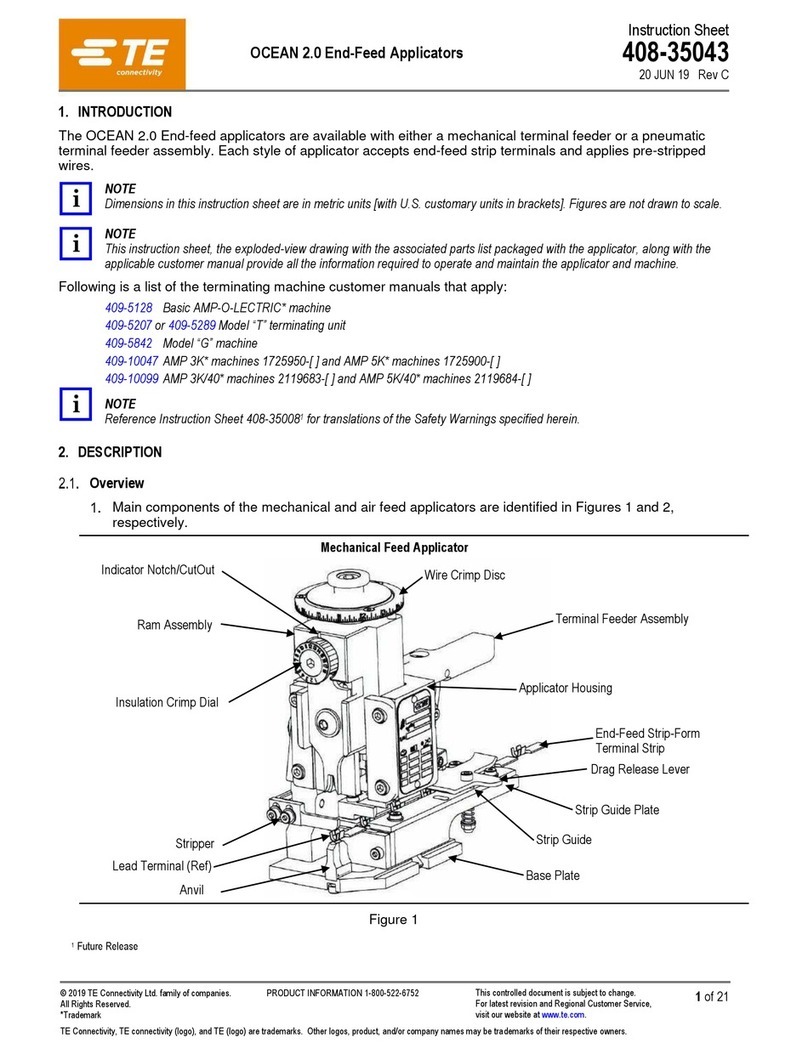
TE Connectivity OCEAN 2.0 User manual

TE Connectivity

TE Connectivity OCEAN 2.0 User manual

TE Connectivity 58372- 1 User manual

TE Connectivity

TE Connectivity 58372- 1 User manual

TE Connectivity CXP 2018681-1 User manual

TE Connectivity

TE Connectivity CXP 2018681-1 User manual

TE Connectivity Ocean 1.0 User manual

TE Connectivity

TE Connectivity Ocean 1.0 User manual

TE Connectivity 2255140-1 User manual

TE Connectivity

TE Connectivity 2255140-1 User manual

TE Connectivity 1725062-1 User manual

TE Connectivity

TE Connectivity 1725062-1 User manual

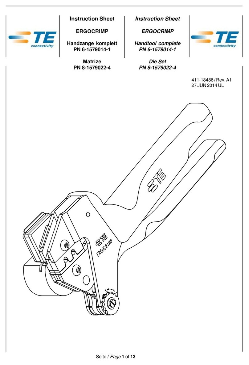
TE Connectivity ERGOCRIMP 6-1579014-1 User manual

TE Connectivity

TE Connectivity ERGOCRIMP 6-1579014-1 User manual

TE Connectivity 2430769-1 User manual

TE Connectivity

TE Connectivity 2430769-1 User manual

TE Connectivity PRO-CRIMPER III User manual

TE Connectivity

TE Connectivity PRO-CRIMPER III User manual

TE Connectivity 2379255-1 User manual

TE Connectivity

TE Connectivity 2379255-1 User manual

TE Connectivity SDE-SA User manual

TE Connectivity

TE Connectivity SDE-SA User manual

TE Connectivity 58024-1 User manual

TE Connectivity

TE Connectivity 58024-1 User manual

TE Connectivity HT11K User manual

TE Connectivity

TE Connectivity HT11K User manual

TE Connectivity 734185-1 User manual

TE Connectivity

TE Connectivity 734185-1 User manual

TE Connectivity CERTI- LOK Hand Tool Frame Assembly 169400 User manual

TE Connectivity

TE Connectivity CERTI- LOK Hand Tool Frame Assembly 169400 User manual

TE Connectivity 354711-1 User manual

TE Connectivity

TE Connectivity 354711-1 User manual

TE Connectivity 2215038-1 User manual

TE Connectivity

TE Connectivity 2215038-1 User manual

TE Connectivity TERMI-POINT 59865-1 Reference guide

TE Connectivity

TE Connectivity TERMI-POINT 59865-1 Reference guide

TE Connectivity 2255143-1 User manual

TE Connectivity

TE Connectivity 2255143-1 User manual

TE Connectivity 90331- 1 User manual

TE Connectivity

TE Connectivity 90331- 1 User manual

TE Connectivity SDE-SA User manual

TE Connectivity

TE Connectivity SDE-SA User manual

TE Connectivity CERTI-CRIMP II Reference guide

TE Connectivity

TE Connectivity CERTI-CRIMP II Reference guide

Popular Tools manuals by other brands

Beveltools Bevel Mate ABA-12 Operation manual

Beveltools

Beveltools Bevel Mate ABA-12 Operation manual

ICON TDST-41 SAE Owner's manual & safety instructions

ICON

ICON TDST-41 SAE Owner's manual & safety instructions

Traditional Tool Repair DTF-56 operating instructions

Traditional Tool Repair

Traditional Tool Repair DTF-56 operating instructions

wattstopper FSIR-100 user guide

wattstopper

wattstopper FSIR-100 user guide

Power Fist 8536609 user manual

Power Fist

Power Fist 8536609 user manual

Power Tec 70316 instruction sheet

Power Tec

Power Tec 70316 instruction sheet

Sparta JAMESON Snip Grip 32-40 quick start guide

Sparta

Sparta JAMESON Snip Grip 32-40 quick start guide

Equalizer FA4TM Operator's instruction manual

Equalizer

Equalizer FA4TM Operator's instruction manual

Sel S 45 instruction manual

Sel

Sel S 45 instruction manual

Unimax MF127 user manual

Unimax

Unimax MF127 user manual

Pro's Kit FB-1688 manual

Pro's Kit

Pro's Kit FB-1688 manual

Air TEc EXTENDO EX-3 instruction manual

Air TEc

Air TEc EXTENDO EX-3 instruction manual

NetComm Wireless AIMWLLR0-35 quick start guide

NetComm Wireless

NetComm Wireless AIMWLLR0-35 quick start guide

Master cool 43012 manual

Master cool

Master cool 43012 manual

Power Fist 8536773 user manual

Power Fist

Power Fist 8536773 user manual

parktool HHP-3 instructions

parktool

parktool HHP-3 instructions

Master cool 71700 operating instructions

Master cool

Master cool 71700 operating instructions

Equalizer TFA12TI Operator's instruction manual

Equalizer

Equalizer TFA12TI Operator's instruction manual

manuals.online logo
manuals.online logoBrands
  • About & Mission
  • Contact us
  • Privacy Policy
  • Terms and Conditions

Copyright 2025 Manuals.Online. All Rights Reserved.