408-35043
Rev C
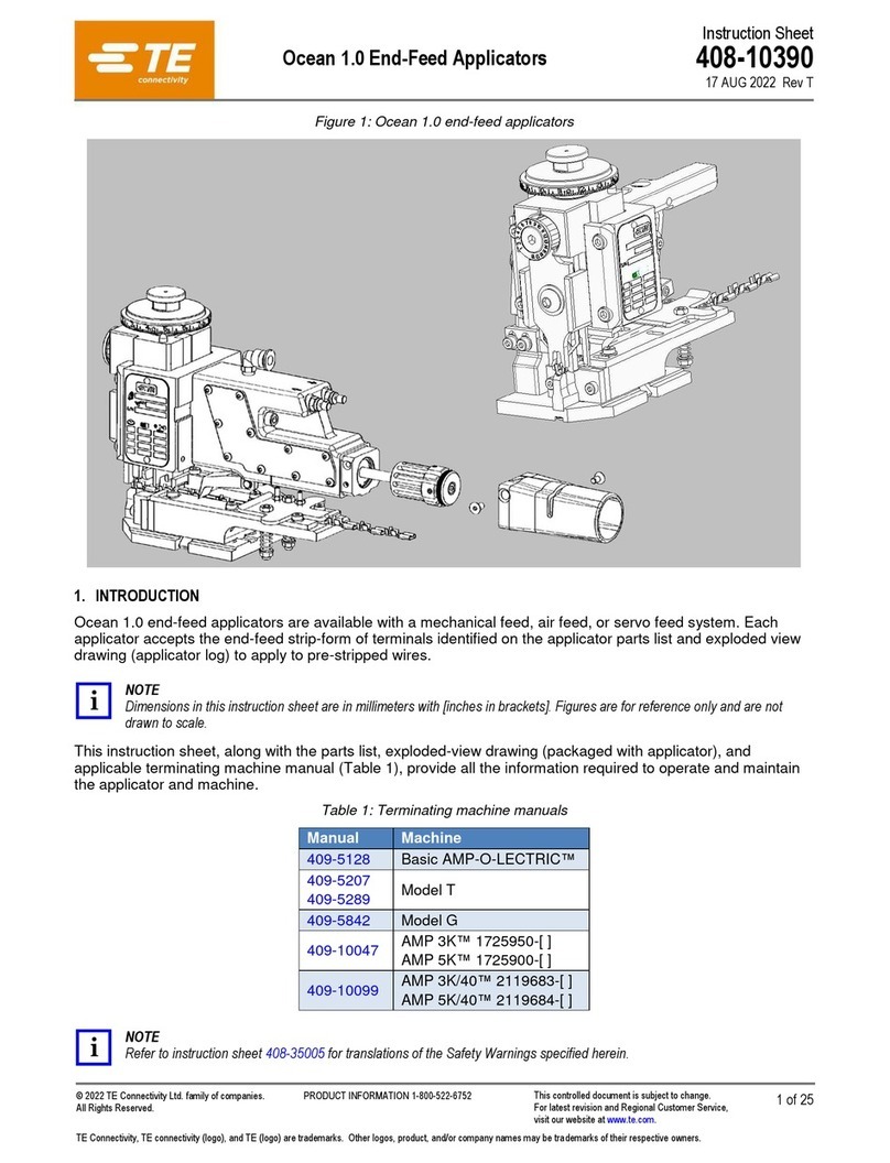
Though the Atlantic and Pacific ram and base plate interfaces are different, most of the Ocean
applicator features and adjustments are the same.
The terminal strip must be fed into the applicator, with the wire barrels facing up and first into the
applicator, between the strip guide plates. It will pass under the stock drag, and the lead terminal will
be positioned over the anvil (for pre-feed applicators) or one terminal length from the anvil (for post-
feed applicators). The feed pawl will feed one terminal during each cycle of the machine. The ram post
(also referred to as the ram mounting post) will engage the post adapter of the machine ram and the
machine ram will actuate the applicator.
The Wire Crimp Disc is located just below the Ram Post Interface, which is designed with a spring-
loaded adjustment mechanism for precise crimp height adjustment increments of 0.01 mm [.0004 in.]
and a total adjustment range of 1.45 mm [.057 in.]. By rotating the wire crimp disc, the ram interface
raises and lowers relative to the applicator housing. The indicator notch of the ram points to the
numbers on the outer diameter of the wire crimp disc, indicating a relative crimp height.
The Wire Crimper and Insulation Crimper are held in a pre-set position by the ram and the crimper
bolt. The insulation crimper is free to move up and down so that the insulation crimp height can be
adjusted via the insulation crimp dial by pulling the spring-loaded dial out slightly and rotating to a
different number.
The slug blade, which cuts the connection tab from the strip between the lead and second terminals,
is also attached to the bottom of the ram. The spring-loaded terminal hold-down, located on the ram,
holds the terminal in place during the crimping and slugging process.
The applicator mounting surface is the base plate. The anvil, strip guide plate, and applicator housing
are mounted on the base plate. The strip guides, stock drag, front and rear shear plates, and strip
hold-down plate are all mounted on the strip guide plate. The shear plates are spaced to allow the
slug blade to pass between them, removing the connecting tab between the terminals.
Lubrication
Some terminal strips require the use of a terminal lubricant. Wick-type lubricators apply lubricant to the
terminal strip as it feeds into the applicator. Terminal lubricants reduce tooling wear and help reduce
damage to the plating on some terminals. The OCEAN applicator End-Feed Lubricator Assembly PN
2119955-2 is available.
CAUTION
Depending on the final use of the crimped terminal, terminal lubrication is not always recommended. To determine if your
applications warrant the use of a terminal lubricator, contact your Field Representative.
NOTE
If your application warrants the use of a terminal lubricator, the recommended lubricant is Stoner Mechanical Lubricant E807
available from Stoner, Inc. Call 1-800-227-5538 or visit www.stonersolutions.com.
Applicator with Mechanical Feed System
With a mechanical feed applicator, the terminals are fed by the action of the feed cam and a series of rods and
levers, which move the feed pawl. Two feed cams are available and can be mounted in two different mounting
holes depending on machine stroke length and feed type (see Figure 6).
NOTE
The recommended setup for end-feed applications is post-feed. The applicator can be configured for pre-feed but may
encounter problems with some applications. Feed issues or terminal jamming may occur in the pre-feed configuration.
NOTE
Pacific applicators can only be used with 30-mm stroke machines and, therefore, only have the 30-mm feed cam mounting
positions on the applicator ram.
NOTE
The Post-Feed feed cam advances the lead terminal over the anvil on the downward stroke of the ram assembly. The Post-
Feed set up is typically used for leadmaker and end-feed bench applications. The Pre-Feed feed cam advances the lead
terminal over the anvil on the upward stroke of the ram assembly so that a terminal is over the anvil when the machine is at
rest. The Pre-Feed set up is typically used for side-feed bench applications.
NOTE
When not in use, the spare Feed Cam can be mounted to the applicator housing in the Spare Feed Cam Storage Location;
see Figure 7.
