manuals.online logo
Brands
  1. Home
  2. •
  3. Brands
  4. •
  5. Teknion
  6. •
  7. Indoor Furnishing
  8. •
  9. Teknion Interpret Operating and maintenance instructions

Teknion Interpret Operating and maintenance instructions

Part and Product Identification
Section:
Description: Page No:
Date:
Rev. No: 6
HEIGHT ADJUSTABLE CANTILEVER, PUCKS AND BOLT KIT - DOUBLE SIDED
FRAMES, SUPPORTS AND WORKSURFACES
Jun 2017 1 of 11
INT_007a
interpret
Installation Guides
Height Adjustable Stacker Pucks (WWSPK), Bolt Kit (WWSBK)
and Height Adjustable Cantilever (WWSCT)
B1 - Height Adjustable Threaded Rod
(E01-0795) x 1
For Customer Support please contact
[email protected]
A
B2 - 1/4 - 20 UNC. Nut Hex Keps Zinc
(E03-0059) x 1
B3 - 5/16 -18 Socket Head Cap Screw
(E01-0781) x 4 for 1" increment or
(E01-0778) x 4 for 2" increment or
(E01-0780) x 4 for 3" increment
C1 - Center Rail Height Adjustable Bracket
(A15-9865) 48" - 60" Length x4
66" - 96" Length x8
C2 - Center Rail Height Adjustable Clamp
(A16-4966) 48" - 60" Length x2
66" - 96" Length x4
C3 - Worksurface Spacer Block
(A25-0547) 48" - 60" Length x2
66" - 96" Length x4
A - Height Adjustable Stacker Puck
(WWSPK) 2 per each inch increment
B4 - 5/16 - 18 Hex Nut, 1/2 A/F .265 Thick
(E03-0755) x 4
C4 - 1/4-20x5/8" Machine Screw, Black Quad,
Truss (E01-0113) 48" - 60" Length x8
66" - 96" Length x16
C5 - #10 x 0.875" Long Screw Quad Pan Washer
(E07-0077) 48" - 60" Length x8
66" - 96" Length x16
C6 - 5/16 - 18 x 3.5 Length Hex Cap
(E01-0758) 48" - 60" Length x4
66" - 96" Length x8
C7 - 5/16 - 18 Hex Nut, 1/2 A/F .265 Thick
(E01-0755) 48" - 60" Length x4
66" - 96" Length x8
C1
C3
C2
Worksurface (WWWRW)
B - WWSBK x2
NOTE: Double Sided Complete Frame shown as
example. Please refer to Installation Guide INT_001
& INT_002 for Frame assembly instructions.
Section:
Description: Page No:
Date:
ATTACH CENTER TRANSVERSE BEAM FASTEN CENTER TRANSVERSE BEAM
INT_007a
2 of 11
Jun 2017
HEIGHT ADJUSTABLE CANTILEVER, PUCKS AND BOLT KIT - DOUBLE SIDED
FRAMES, SUPPORTS AND WORKSURFACES
interpret
Installation Guides
STEP 2: Fasten Transverse Beam to both Gables, and level Frames.
NOTE: DO NOT FULLY TIGHTEN.
STEP 1: Please assemble Gables and Transverse Beam by referring to Installation Guide
INT_001 Step 1 to 3. Align pilot holes on Gables and Clamps, then attach the center Beam to
both Gables as shown.
NOTE: Make sure DO NOT
TIGHTEN FULLY.
NOTE: Parts labeled with full name are belong to
Double Sided Frame.
Please assemble Gables and Transverse Beam by
referring to Installation Guide INT_001 for
Complete Frame or INT_002 for multiple Frames.
Center Transverse Beam
Gable Screw
Nut
Section:
Description: Page No:
Date:
NOTE ATTACH SIDE TRANSVERSE BEAMS (END)
INT_007a
3 of 11
Jun 2017
HEIGHT ADJUSTABLE CANTILEVER, PUCKS AND BOLT KIT - DOUBLE SIDED
FRAMES, SUPPORTS AND WORKSURFACES
interpret
Installation Guides
NOTE: Up to 3 Pucks can be used STEP 3a: Align pilot holes on Gables and Clamps, and attach side Transverse Beams to both
Gables.
2" Increment
0" Increment
3" Increment
1" Increment
Side View
IMPORTANT: DO NOT FULLY TIGHTEN.
B3
Clamp
A
Clamp
B4
NOTE: End connection with
1" increment shown.
Section:
Description: Page No:
Date:
SIDE TRANSVERSE BEAM ASSEMBLY (MID) ATTACH SIDE TRANSVERSE BEAMS
INT_007a
4 of 11
Jun 2017
HEIGHT ADJUSTABLE CANTILEVER, PUCKS AND BOLT KIT - DOUBLE SIDED
FRAMES, SUPPORTS AND WORKSURFACES
interpret
Installation Guides
STEP 3b: Please assemble Pucks and Clamps with Beam as shown. DO NOT FULLY TIGHT.
NOTE: Each Block provides 1" of height increment. Please refer to Specification Drawing for
quantity of Pucks to be used.
STEP 4: Align pilot holes on Gables and Clamps, and attach side Transverse Beams to both
Gables.
IMPORTANT: DO NOT FULLY TIGHTEN.
B3
Clamp
A
Clamp
B4
NOTE: Mid connection with
1" increment shown.
Side View
Height Adjustable Side
Regular Side
Section:
Description: Page No:
Date:
FASTEN SIDE TRANSVERSE BEAMS, ATTACH STANDOFFS & CLAMPS
Jun 2017 5 of 11
INT_007a
HEIGHT ADJUSTABLE CANTILEVER, PUCKS AND BOLT KIT - DOUBLE SIDED
FRAMES, SUPPORTS AND WORKSURFACES
interpret
Installation Guides
STEP 5: Fasten Clamps to Gables loosely, then level Frame. Rest Height Adjustable Clamps on Center Transverse Beam as show, and attach Standoffs to side Transverse Beams. If Electrics are
specified, leave enough space between Blocks and install after this step.
NOTE: DO NOTE TIGHTEN FULLY. Make sure Square and Level the Frame before proceed to next step.
C2
B3
STANDOFF
B4
Worksurface
Spacer Block
NOTE: DO NOT TIGHTEN
FULLY.
Make sure Square and Level the
Frame before proceed to next
step.
Cantilevers (shown) are
delivered with Frame.
These will NOT be used.
KEEP ON SITE FOR
FUTURE RETROFIT.
Section:
Description: Page No:
Date:
CENTER RAIL ASSEMBLY INSERT CENTER RAIL
INT_007a
6 of 11
Jun 2017
HEIGHT ADJUSTABLE CANTILEVER, PUCKS AND BOLT KIT - DOUBLE SIDED
FRAMES, SUPPORTS AND WORKSURFACES
interpret
Installation Guides
STEP 6: Prepare Center Rail for installation by sliding mounting Bolts into the Channels
underside of the Rail. Slide End Caps on both sides. Tighten Setscrews to secure in place.
Side End Cap
STEP 7: Turn Center Rail so the Hex Cap Screws are facing down. Slide Screws on the Rail
to line up with corresponding pilot holes on the Height Adjustable Clamps, Clamp Brackets,
and Worksurface Spacer Block. Drop the Rail on the top of Center Transverse Beam. Make
sure all Screws are inserted into the pilot holes.
NOTE: Leave space required to
install Power Module
Hex Head
Screw
Center Rail
Assembly
C6
Section:
Description: Page No:
Date:
FASTEN SPACER BLOCKS AND CENTER RAIL
Jun 2017 7 of 11
INT_007a
HEIGHT ADJUSTABLE CANTILEVER, PUCKS AND BOLT KIT - DOUBLE SIDED
FRAMES, SUPPORTS AND WORKSURFACES
interpret
Installation Guides
STEP 8: Use Spacer Blocks and Nuts to secure the Center Rail with the Frame.
NOTE: Install Top Cap ONLY if there are no Screens or Storage are specified.
C3
Worksurface
Spacer Block
Hex Nut
B4
Underside View
Section:
Description: Page No:
Date:
FASTEN BRACKETS TO CLAMPS
Jun 2017 8 of 11
INT_007a
HEIGHT ADJUSTABLE CANTILEVER, PUCKS AND BOLT KIT - DOUBLE SIDED
FRAMES, SUPPORTS AND WORKSURFACES
interpret
Installation Guides
STEP 9: Align Brackets and Clamps as per configurations shown in Illustration, then fasten with Screws provided.
NOTE: Use indicated pilot holes to secure Bracket to Clamp according to Illustration shown on right. 1" increment shown as an example.
C4
C1
3 Stacker Pucks
2 Stacker Pucks
1 Stacker Pucks
0 Stacker Pucks
NOTE: Only use if another
side of Frame DOES NOT
require height adjustment.
Cantilever
Cantilever
Cantilever
Cantilever
Side View
NOTE: 1" increment
shown as an example.
Section:
Description: Page No:
Date:
FASTEN THREADED ROD WITH WORKSURFACE
Jun 2017 9 of 11
INT_007a
HEIGHT ADJUSTABLE CANTILEVER, PUCKS AND BOLT KIT - DOUBLE SIDED
FRAMES, SUPPORTS AND WORKSURFACES
interpret
Installation Guides
STEP 10: Align pilot holes from Worksurface with Clamps. Insert Threaded Rod through Clamps and fasten. Fasten Nuts to secure Worksurface in place, then cut excess Threaded Rod at
location indicated on illustration.
NOTE: To prevent Threaded Rod penetrating top of Worksurface, please refer to next Page for dimensions to be fasten.
Worksurface
B2
B1
Side ViewUnderside View
B2
B1
Flat head Machine
Screw Quadrex
NOTE: To prevent Threaded Rod penetrating
top of Worksurface, please refer to next Page
for dimensions to be fasten.
Please use Screws provided from Frame
package to fasten the regular
side Worksurface.
3 5/8"
1 5/8"
2 5/8"
Section:
Description: Page No:
Date:
CUT THREADED ROD
Jun 2017 10 of 11
INT_007a
HEIGHT ADJUSTABLE CANTILEVER, PUCKS AND BOLT KIT - DOUBLE SIDED
FRAMES, SUPPORTS AND WORKSURFACES
interpret
Installation Guides
STEP 11: Cut excess Threaded Rod at location indicated on illustration.
NOTE: To prevent Threaded Rod penetrating top of Worksurface, please follow dimensions given.
Cut
Cut
Cut
Section:
Description: Page No:
Date:
FASTEN CENTER HEIGHT ADJUSTABLE BRACKET TO WORKSURFACE
Jun 2017 11 of 11
INT_007a
HEIGHT ADJUSTABLE CANTILEVER, PUCKS AND BOLT KIT - DOUBLE SIDED
FRAMES, SUPPORTS AND WORKSURFACES
interpret
Installation Guides
STEP 12: Fasten Brackets to Worksurface from underneath with Screws provided.
Detail View
C5
Worksurface

Other manuals for Interpret

9

Other Teknion Indoor Furnishing manuals

Teknion Navigate 120 HA Frame HNBFNT Operating and maintenance instructions

Teknion

Teknion Navigate 120 HA Frame HNBFNT Operating and maintenance instructions

Teknion HWBLSF Operating and maintenance instructions

Teknion

Teknion HWBLSF Operating and maintenance instructions

Teknion district WBP User manual

Teknion

Teknion district WBP User manual

Teknion XAFGM Series Operating and maintenance instructions

Teknion

Teknion XAFGM Series Operating and maintenance instructions

Teknion NUOVA CONTESSA Owner's manual

Teknion

Teknion NUOVA CONTESSA Owner's manual

Teknion UNSF User manual

Teknion

Teknion UNSF User manual

Teknion height-adjustable bench Operating and maintenance instructions

Teknion

Teknion height-adjustable bench Operating and maintenance instructions

Teknion transit Operating and maintenance instructions

Teknion

Teknion transit Operating and maintenance instructions

Teknion HABCDG Series Operating and maintenance instructions

Teknion

Teknion HABCDG Series Operating and maintenance instructions

Teknion interpret WWSDC Operating and maintenance instructions

Teknion

Teknion interpret WWSDC Operating and maintenance instructions

Teknion hiSpace User manual

Teknion

Teknion hiSpace User manual

Teknion Interpret User manual

Teknion

Teknion Interpret User manual

Teknion HTNB User manual

Teknion

Teknion HTNB User manual

Teknion Single-Sided Rectangular Worksurface User manual

Teknion

Teknion Single-Sided Rectangular Worksurface User manual

Teknion RKXD Operating and maintenance instructions

Teknion

Teknion RKXD Operating and maintenance instructions

Teknion Marini Owner's manual

Teknion

Teknion Marini Owner's manual

Teknion t-3 Owner's manual

Teknion

Teknion t-3 Owner's manual

Teknion Leverage Operating and maintenance instructions

Teknion

Teknion Leverage Operating and maintenance instructions

Teknion mina User manual

Teknion

Teknion mina User manual

Teknion Emote User manual

Teknion

Teknion Emote User manual

Teknion Sidewise SWDBA User manual

Teknion

Teknion Sidewise SWDBA User manual

Teknion Upstage User manual

Teknion

Teknion Upstage User manual

Teknion PUNT Stockholm Storage Operating and maintenance instructions

Teknion

Teknion PUNT Stockholm Storage Operating and maintenance instructions
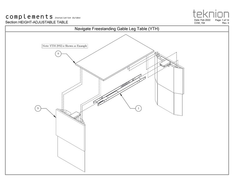
Teknion Dossier ZJRP Operating and maintenance instructions
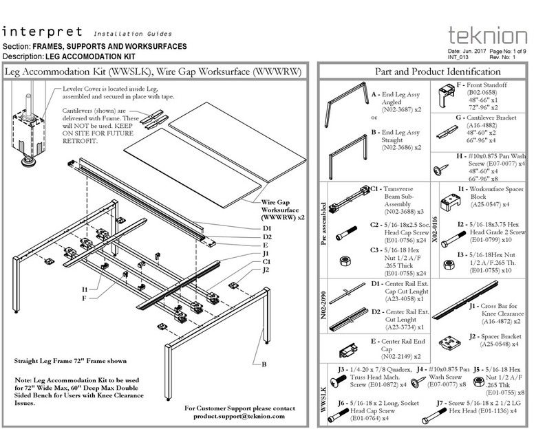
Teknion

Teknion Dossier ZJRP Operating and maintenance instructions
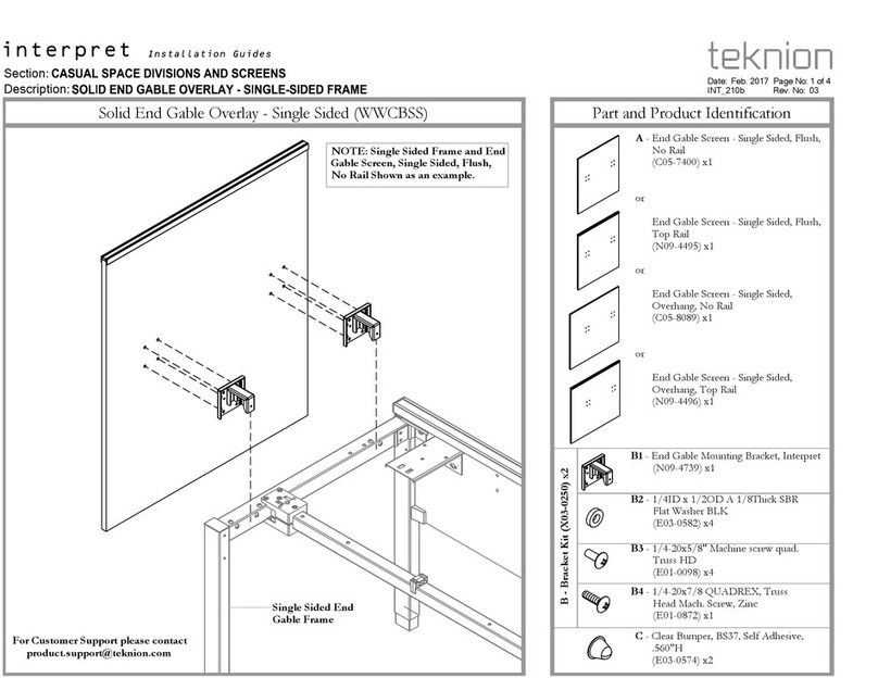
Popular Indoor Furnishing manuals by other brands
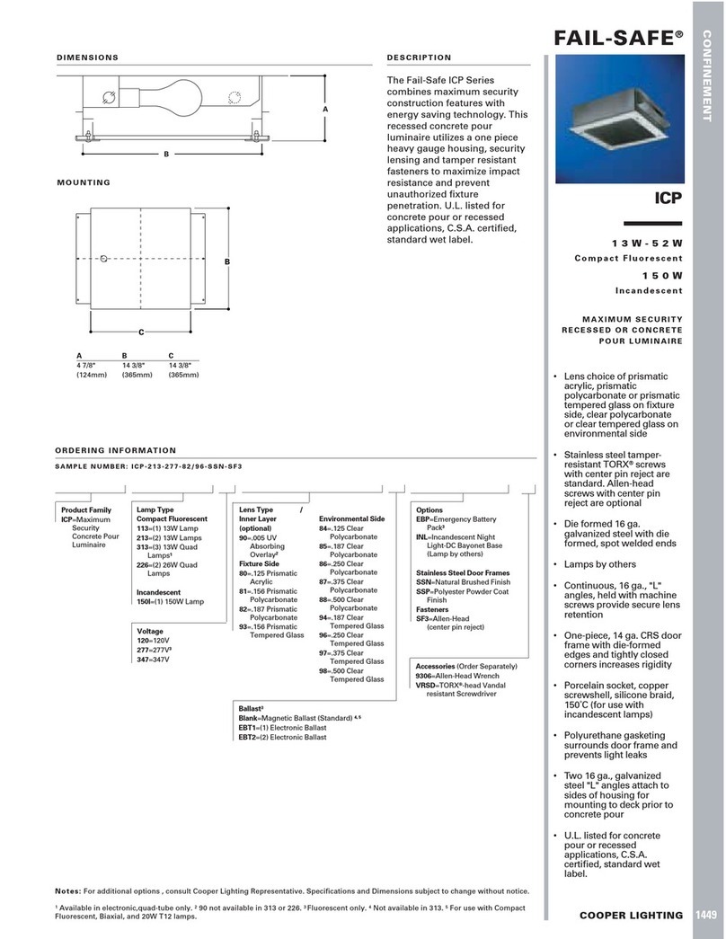
New Classic Furniture PRAIRIE POINT D058B-22 Assembly instructions

New Classic Furniture

New Classic Furniture PRAIRIE POINT D058B-22 Assembly instructions

PEERLESS ACCSH100 Installation and assembly

PEERLESS

PEERLESS ACCSH100 Installation and assembly

Coaster Mina 193772 Assembly instructions

Coaster

Coaster Mina 193772 Assembly instructions

pottery barn kids SPINDLE PLAY CHAIR quick start guide

pottery barn kids

pottery barn kids SPINDLE PLAY CHAIR quick start guide

pemora CUBO LED instruction manual

pemora

pemora CUBO LED instruction manual

Atlantic Solo TV stand Assembly instructions

Atlantic

Atlantic Solo TV stand Assembly instructions

Epic Office Furniture AXIS AXPBOX200 Assembly instruction

Epic Office Furniture

Epic Office Furniture AXIS AXPBOX200 Assembly instruction

DeFehr STOCKTON PANEL BED manual

DeFehr

DeFehr STOCKTON PANEL BED manual

Coaster 100623 Assembly instructions

Coaster

Coaster 100623 Assembly instructions

Costway OP70607 user manual

Costway

Costway OP70607 user manual

Ercol Pero 2360 quick start guide

Ercol

Ercol Pero 2360 quick start guide

GWF Galicia 150cm Wall TV Unit with LED Assembly instructions

GWF

GWF Galicia 150cm Wall TV Unit with LED Assembly instructions

Moduspace MAX70plus Assembly guide

Moduspace

Moduspace MAX70plus Assembly guide

KidKraft 53285 Assembly instructions

KidKraft

KidKraft 53285 Assembly instructions

Femo FM-2167 quick start guide

Femo

Femo FM-2167 quick start guide

modway EEI –2853 quick start guide

modway

modway EEI –2853 quick start guide

Rauch M2659 Assembly instructions

Rauch

Rauch M2659 Assembly instructions

Mayline Sterling Series Assembly instructions

Mayline

Mayline Sterling Series Assembly instructions

manuals.online logo
manuals.online logoBrands
  • About & Mission
  • Contact us
  • Privacy Policy
  • Terms and Conditions

Copyright 2025 Manuals.Online. All Rights Reserved.