manuals.online logo
Brands
  1. Home
  2. •
  3. Brands
  4. •
  5. Teknion
  6. •
  7. Indoor Furnishing
  8. •
  9. Teknion Height-adjustable bench Operating and maintenance instructions

Teknion Height-adjustable bench Operating and maintenance instructions

Section:
Date: May 2020
METAL GABLES & CABLE CHANNEL
height-adjustable bench
Installation Guides
Rev. 01
Page: 1 of 18
HABN_223a
1
1.3
2.2
3.3
3.4
3.1
3.1
3.4
3.2
2.3
2.4
REV.#
By.
Date.
Chkd.
Description.
00
NK\AL
May 2019
XX
New Release
01
NK
Sept 2019
XX
Implemented
Roma's Feed Backs
Navigate End Gable - Metal (HNBCGEMN), Navigate Mid Gable - Metal (HNBCGMMN), Navigate Cable Channel
(HNBFCN)
Section:
Date: May 2020
METAL GABLES & CABLE CHANNEL
height-adjustable bench
Installation Guides
Page: 2 of 18
HABN_223a
ITEM
NO.
PREVIEW
DESCRIPTION
PART
NUMBER
QTY
.
1. Navigate Wire Channel (HNBFCN) x1
1
CABLE
CHANNEL ASSY
HNBFCNB
1
1.1
CENTER RAIL
EXTRUSION
CAP CUT
LENGTH
A23-5200-X
1
1.2
ACCESS DOOR
NAVIGATE
WIRE CHANNEL
N01-4420
2
1.3
SUPPORT BRKT
- SCREEN RAIL
A16-3009
2
ITEM
NO.
PREVIEW
DESCRIPTION
PART
NUMBER
QTY
.
1.4
5/16-18 HEX
NUT, 1/2 A/F,
.265 THK.
E01-0755
8
1.5
1/4-20X5/8"
MACH SCR,
BLACK,
QUAD,TRUSS
E01-0113
8
1.6
#8-
18X1/2"CROSS
SQUARE
COMB.SELF
E07-0012
12
1.7
HANGER - CLUB
TALK
A16-2364
2
1.8
WIRE
MANAGER CLIP
B02-2007
16
Part & Product Identification
Section:
Date: May 2020
METAL GABLES & CABLE CHANNEL
height-adjustable bench
Installation Guides
Page: 3 of 18
HABN_223a
ITEM
NO.
PREVIEW
DESCRIPTION
PART
NUMBER
QTY.
1
NAVIGATE WIRE
CHANNEL DOUBLE
SIDED
HNBFCNB\70
1
1.1
1.2
1.3
1.4
1.4.1
1.4.1.1
1.4.2
1.5
1.6
1.7
1.8
1.9
ITEM
NO.
PREVIEW
DESCRIPTION
PART
NUMBER
QTY.
2. Navigate End Gable - Metal (HNBCGEMN) x1
2.1
INSIDE COVER ASSY FOR
METAL END GABLE,
DOUBLE SIDED, HAB
N09-8810-X
1
2.2
INSIDE COVER FOR
METAL END GABLE,
DOUBLE SIDED, HAB
A16-7473-X
1
2.3
2A1 FOAM RUBBER 3/16
THICK 1/2" WIDE 1"
LONG, GREY CLOSED
CELL
E08-0134
4
2.4
GABLE CONNECTING
PLATE
A16-3651
2
2.5
#10x1/2" TAP SCR QUAD,
PAN
E01-0023
2
ITEM
NO.
PREVIEW
DESCRIPTION
PART
NUMBER
QTY.
3. Navigate Mid Gable - Metal (HNBCGMMN) x1
3.1
&
TOP COVER FOR METAL
MID GABLE W/ POWER
POLE, HAB
A16-3085
&
A16-3086
1
Each
3.2
SIDE COVER ASSY
W/CABLE & BASEFEED
CUTOUT FOR METAL MID
GALBE, HAB
N09-5183-X
1
3.3
SIDE COVER ASSY
W/CABLE CUTOUT FOR
METAL MID GALBE, HAB
N09-5185-X
1
3.4
FRONT COVER ASSY FOR
METAL MID GABLE, HAB
N09-5182
2
3.5
1/2" DIAMETER x 1/8"
THICK CIRCULAR RARE
EARTH MAGNET
D03-0059
4
3.6
TOP COVER FOR METAL
MID GABLE W/ POWER
POLE, HAB (OPTIONAL)
A16-3025
2
Part & Product Identification
Section:
Date: May 2020
METAL GABLES & CABLE CHANNEL
height-adjustable bench
Installation Guides
Page: 4 of 18
HABN_223a
1
1.3
NOTE: Make sure the Bolts do not come out of the assembly.
1.4
STEP 1: Remove Support Brackets.
REMOVE SUPPORT BRACKETS
Section:
Date: May 2020
METAL GABLES & CABLE CHANNEL
height-adjustable bench
Installation Guides
Page: 5 of 18
HABN_223a
1.3
2.1
2.3
C
L
APPLY FOAM RUBBERS
STEP 2: Attach Foam Rubbers onto the centre of the Table Legs' inner side.
STEP 3: Insert Support Bracket through the cut-out on the Inside Cover Assembly as shown.
ATTACH SUPPORT BRACKET
Section:
Date: May 2020
METAL GABLES & CABLE CHANNEL
height-adjustable bench
Installation Guides
Page: 6 of 18
HABN_223a
2.4
NOTE: Parts of the Frames are
hidden for Illustration Purpose.
Stretcher
Bar
ATTACH CONNECTING PLATES TO FRAME LEGS
STEP 4: Loosen Legs Hex Bolt on both Legs to allow enought clearance for gable connecting
plate. Then Fasten Gable Connecting Plates to Frame Legs.
STEP 5: Mount Inside Cover Assembly onto Frame Stretcher Bar.
MOUNT INSIDE COVER
Section:
Date: May 2020
METAL GABLES & CABLE CHANNEL
height-adjustable bench
Installation Guides
Page: 7 of 18
HABN_223a
2.5
1.5
SECURE INSIDE COVER ASSEMBLY TO FRAME
STEP 6: Secure Inside Cover Assembly to Stretcher Bar with Bolts.
STEP 7: Make sure the face of the Inside Cover Assembly is flush with the Leg. Secure Inside
Cover Assembly to Gable Connecting Plate on both sides using Tap Quad Pan screws
provided.
FASTEN INSIDE COVER IN PLACE
Section:
Date: May 2020
METAL GABLES & CABLE CHANNEL
height-adjustable bench
Installation Guides
Page: 8 of 18
HABN_223a
2.2
Opposite side view
2.2
STEP 8:Mount Outside Cover Assembly to the highlighted part of the Inside Cover Assembly as shown.
MOUNT OUTSIDE COVER ASSEMBLY
Section:
Date: May 2020
METAL GABLES & CABLE CHANNEL
height-adjustable bench
Installation Guides
Page: 9 of 18
HABN_223a
NOTE: Cable Channels are Hidden for Illustration Purpose.
Connecting
Bracket
1/4-2, 5/8" Long Screw
NOTE:Please refer to installation guide HAB_322b.
Optional: If Mid Power Pole is specified. Please fasten Connecting Bracket to the underside of the Stretcher Bars as shown before Installing Mid Gable.
NOTE: Please refer to installation guide HAB_322b
MID POWER POLE SUPPORT PLATE (OPTIONAL)
Section:
Date: May 2020
METAL GABLES & CABLE CHANNEL
height-adjustable bench
Installation Guides
Page: 10 of 18
HABN_223a
1.5
3.2
NOTE: Please refer to Specification Drawing
to mount the correct Side Cover Assembly
NOTE: Parts of the Frames are
hidden for Illustration Purpose.
3.2
ATTACH SUPPORT BRACKET
STEP 9: Insert Support Bracket through the cut-out on the Side Cover Assembly.
STEP 10: Mount Side Cover Assembly onto the Stretcher Bar as shown.
NOTE: Please refer to Specification Drawing to mount the correct Side Cover Assembly.
SCREEN AND GABLES
Section:
Date: May 2020
METAL GABLES & CABLE CHANNEL
height-adjustable bench
Installation Guides
Page: 11 of 18
HABN_223a
NOTE: Parts of the Frame are
Hiiden for Illustration Purpose.
NOTE: Electrics components to be
installed on Cable Channel before
connecting to support Bracket. Please refer
to Installation Guide 321a, 321b, 322a,
322b for corresponding Electric installation.
NOTE:Install Cable Channel Cover Plate on Cable Channel
Where E-Chain is not specified or unused location.
1.6
1.5
Power Module Cover
Receptacle Outlet
Power Harness
I - Connector
NOTE: Electrics are not included
with the Cable Channel.
1.7
1.8
?
SECURE SIDE COVER ASSEMBLY
STEP 11: Secure Side Cover Assembly with Stretcher Bar with Bolts
NOTE: Electrics components to be installed on Cable Channel before connecting to Support
Bracket. Please refer to Installation Guide 321a, 321b, 321c,322a or 322b for corresponding
Electrics
installation.
CABLE CHANNEL ASSEMBLY
Section:
Date: May 2020
METAL GABLES & CABLE CHANNEL
height-adjustable bench
Installation Guides
Page: 12 of 18
HABN_223a
1
1.4
Underside View
ATTACH CABLE CHANNEL & CENTER RAIL
STEP 12: Align holes on Support Brackets, Cable Channel Assembly. Insert Bolts inside
Centre Rail Extrusion through Cable Channel Assembly and Brackets as shown.
STEP 13: Secure Cable Channel in place with Nuts.
SECURE CABLE CHANNEL
Section:
Date: May 2020
METAL GABLES & CABLE CHANNEL
height-adjustable bench
Installation Guides
Page: 13 of 18
HABN_223a
1.3
3.3
ATTACH SUPPORT BRACKET
STEP 14: Insert Support Bracket through the cut-out on the Side Cover Assembly.
STEP 15: Mount Side Cover Assembly onto the Stretcher Bar as shown.
MOUNT SIDE COVER ASSEMBLY
Section:
Date: May 2020
METAL GABLES & CABLE CHANNEL
height-adjustable bench
Installation Guides
Page: 14 of 18
HABN_223a
NOTE: Parts of the Frame are
hidden for Illustration Purpose.
3.5
3.4
1.5
NOTE: Attach Magnets approximately to the locations to the legs
SECURE SIDE COVER ASSEMBLY
STEP 16: Secure Side Cover Assembly with Stretcher Bar with Bolts.
STEP 17: Attach Magnets to the inside of the Front Covers as shown.
NOTE: Attach Magnets approximately to the locations to the legs
ATTACH MAGNET
Section:
Date: May 2020
METAL GABLES & CABLE CHANNEL
height-adjustable bench
Installation Guides
Page: 15 of 18
HABN_223a
NOTE: Make sure Magnets are attached to the Legs.
3.4
NOTE: Legs are Hidden for
Illustration Purpose.
STEP 18: Mount Front Covers onto the Side Covers as shown in Detail View. Repeat this on the other side as well.
NOTE: Make sure Magnets are attached to the legs
MOUNT FRONT COVER ASSEMBLIES
Section:
Date: May 2020
METAL GABLES & CABLE CHANNEL
height-adjustable bench
Installation Guides
Page: 16 of 18
HABN_223a
3.2
3.6
3.6
NOTE: Parts of the Frames are
hidden for Illustration Purpose.
CABLE CHANNEL ASSEMBLY
STEP 19: Align holes on Support Brackets, Cable Channel Assembly. Insert Bolts inside
Center Rail Extrusion through Cable Channel Assembly and Brackets as shown. Secure Cable
Channel in place with Nuts.
STEP 20: Attach Top Covers onto the highlighted extrusions on the Side and Front Cover
Assemblies.
ATTACH TOP COVER
Section:
Date: May 2020
METAL GABLES & CABLE CHANNEL
height-adjustable bench
Installation Guides
Page: 17 of 18
HABN_223a
3.1
3.1
NOTE: Only when Power Pole option is selected.
STEP 21: If Mid gable Power Pole is Specified, attach Top Covers onto the hightlighted extrusions on the Side and Front Cover Assemblies as shown.
TOP COVER WITH POWER POLE COUTOUT (OPTIONAL)
Section:
Date: May 2020
METAL GABLES & CABLE CHANNEL
height-adjustable bench
Installation Guides
Page: 18 of 18
HABN_223a
1.1
1.1
STEP 22: Insert Center Rail Extrusion Caps onto Center Rail Extrusion as Shown.
CENTER RAIL EXTRUSION CAP

This manual suits for next models

3

Other Teknion Indoor Furnishing manuals

Teknion north 56 User manual

Teknion

Teknion north 56 User manual

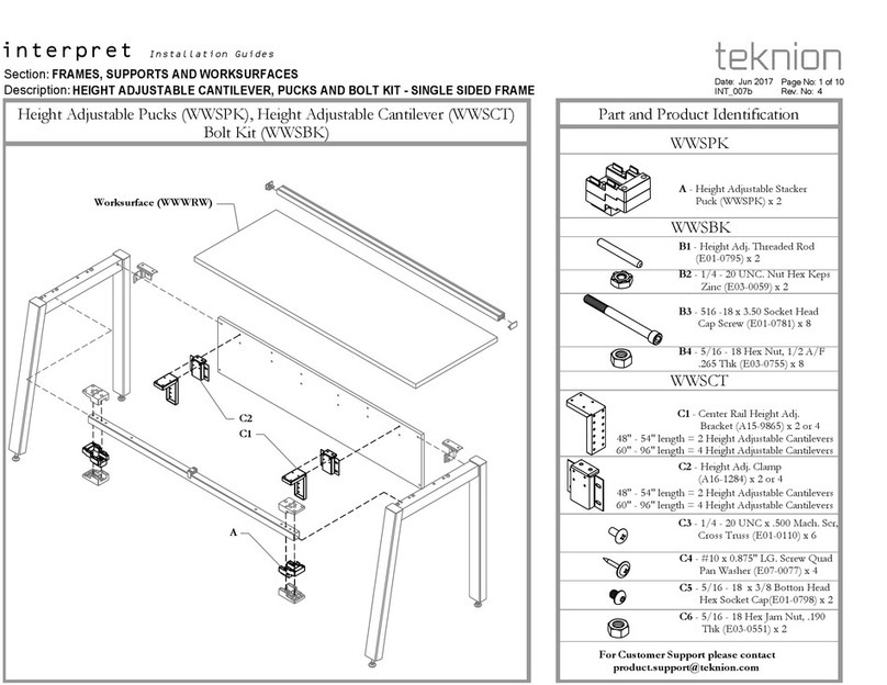
Teknion interpret WWSPK Operating and maintenance instructions
Teknion

Teknion interpret WWSPK Operating and maintenance instructions

Teknion Interpret Operating and maintenance instructions

Teknion

Teknion Interpret Operating and maintenance instructions
Teknion HNBLSF Operating and maintenance instructions

Teknion

Teknion HNBLSF Operating and maintenance instructions
Teknion height-adjustable bench Operating and maintenance instructions

Teknion

Teknion height-adjustable bench Operating and maintenance instructions
Teknion hiSpace User manual

Teknion

Teknion hiSpace User manual

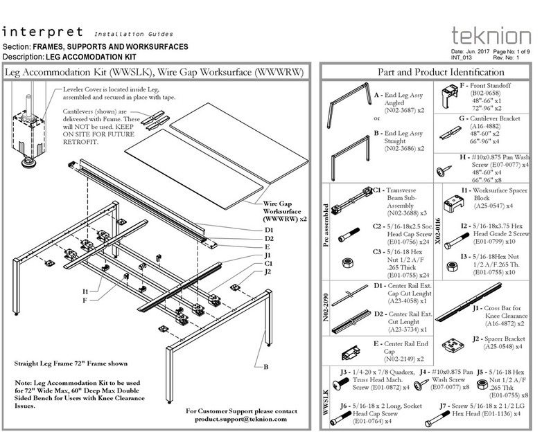
Teknion interpret Leg Accommodation Kit WWSLK Operating and maintenance instructions
Teknion

Teknion interpret Leg Accommodation Kit WWSLK Operating and maintenance instructions

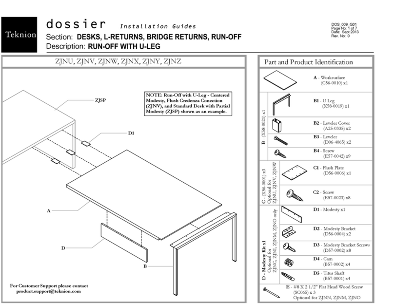
Teknion Dossier Operating and maintenance instructions

Teknion

Teknion Dossier Operating and maintenance instructions
Teknion interpret 120 FRAME CURVE LEG WWSTW User manual
Teknion

Teknion interpret 120 FRAME CURVE LEG WWSTW User manual

Teknion interpret WWCBSD Operating and maintenance instructions
Teknion

Teknion interpret WWCBSD Operating and maintenance instructions

Teknion Complements Operating and maintenance instructions

Teknion

Teknion Complements Operating and maintenance instructions

Teknion NUOVA CONTESSA Owner's manual

Teknion

Teknion NUOVA CONTESSA Owner's manual
Teknion Transit KSB Operating and maintenance instructions
Teknion

Teknion Transit KSB Operating and maintenance instructions

Teknion BSMLHR User manual

Teknion

Teknion BSMLHR User manual

Teknion Dossier Operating and maintenance instructions
Teknion

Teknion Dossier Operating and maintenance instructions

Teknion District User manual

Teknion

Teknion District User manual

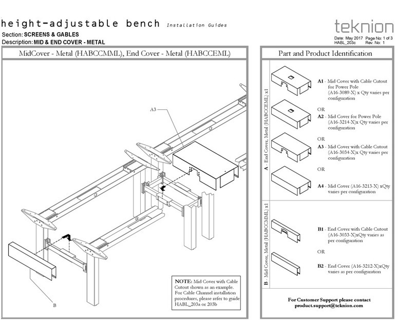
Teknion HABCCMML Operating and maintenance instructions

Teknion

Teknion HABCCMML Operating and maintenance instructions

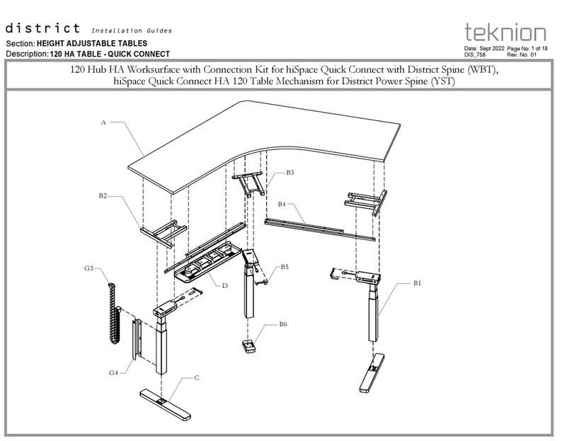
Teknion district 120 Hub HA Worksurface with Connection Kit for hiSpace Quick Connect with District Spine... User manual

Teknion

Teknion district 120 Hub HA Worksurface with Connection Kit for hiSpace Quick Connect with District Spine... User manual

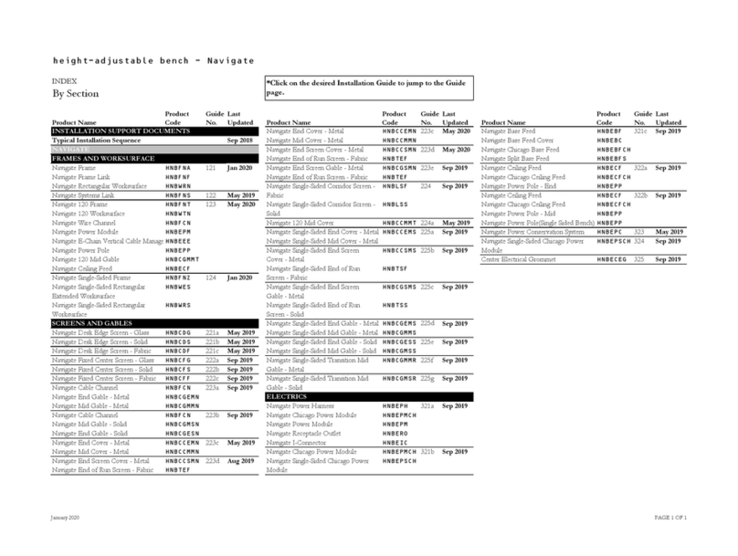
Teknion Complements Operating and maintenance instructions
Teknion

Teknion Complements Operating and maintenance instructions

Teknion Navigate Single-Sided Frame HNBFNZ User manual

Teknion

Teknion Navigate Single-Sided Frame HNBFNZ User manual

Teknion district WBP User manual

Teknion

Teknion district WBP User manual

Teknion NHDS Operating and maintenance instructions

Teknion

Teknion NHDS Operating and maintenance instructions

Teknion expansion cityline hiSpace Quick Connect 120 HA Mechanism... User manual

Teknion

Teknion expansion cityline hiSpace Quick Connect 120 HA Mechanism... User manual

Teknion Emote User manual

Teknion

Teknion Emote User manual

Popular Indoor Furnishing manuals by other brands
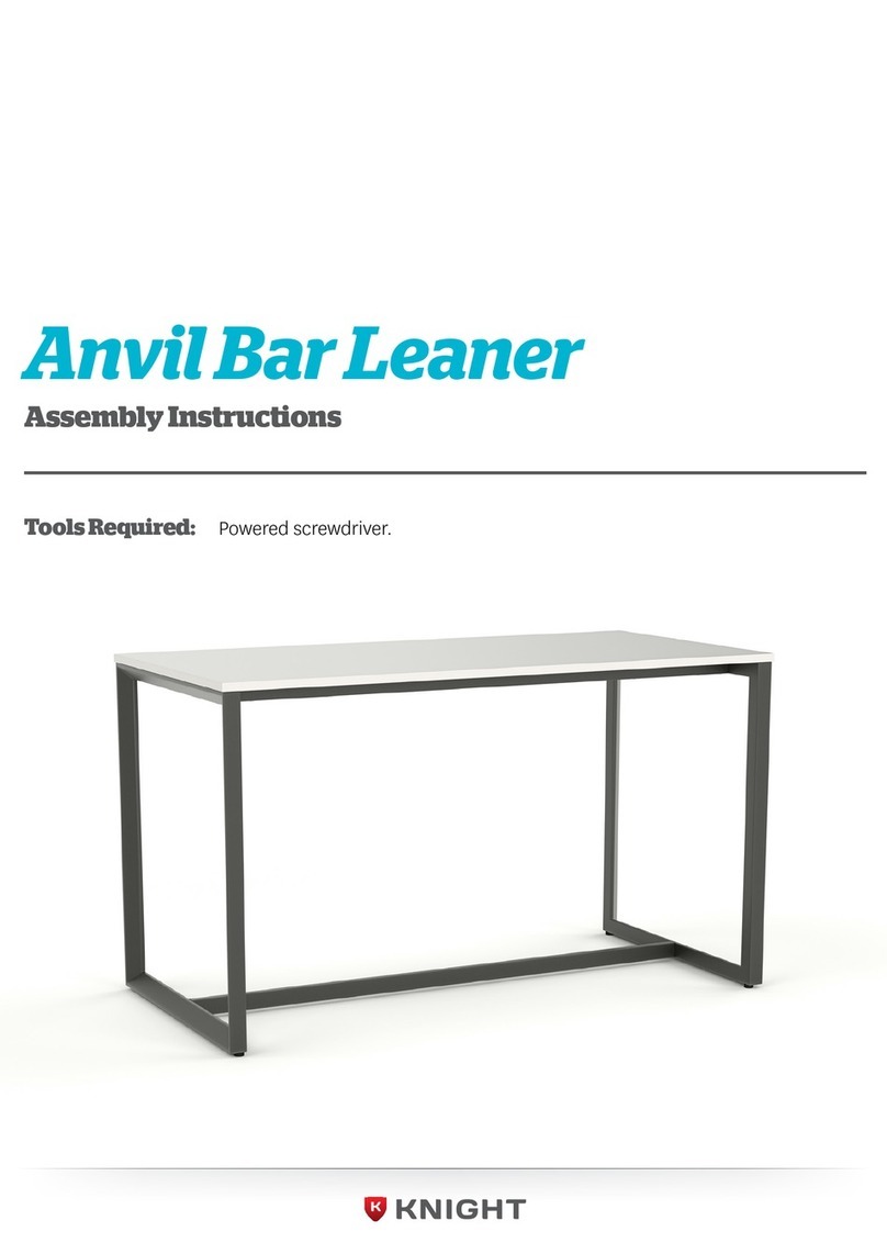
Knight Anvil Bar Leaner Assembly instructions

Knight

Knight Anvil Bar Leaner Assembly instructions

Courtyard Creations TGS62HS-WM Assembly instructions
Courtyard Creations

Courtyard Creations TGS62HS-WM Assembly instructions

Costway KC56890 manual

Costway

Costway KC56890 manual

Micasa VIDRIO Vitrine 4011.001 Assembly instruction
Micasa

Micasa VIDRIO Vitrine 4011.001 Assembly instruction

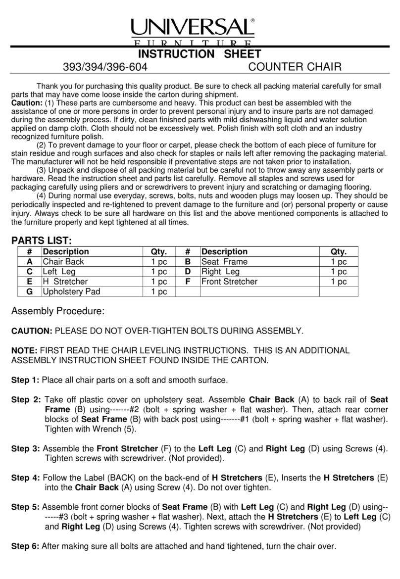
Universal Furniture 394-604 instruction sheet
Universal Furniture

Universal Furniture 394-604 instruction sheet

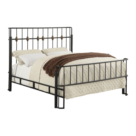
Furniture of America CM7716F Assembly instructions
Furniture of America

Furniture of America CM7716F Assembly instructions

Dorel Home Products DA9027129CL quick start guide

Dorel Home Products

Dorel Home Products DA9027129CL quick start guide

Nightingale EC5 535 Series User handbook
Nightingale

Nightingale EC5 535 Series User handbook

IKEA BESTA UPPLAND ROLL FRONT 24X75" instructions
IKEA

IKEA BESTA UPPLAND ROLL FRONT 24X75" instructions

Stirling 3 TIER SHOE CABINET manual

Stirling

Stirling 3 TIER SHOE CABINET manual
AFi HBFB-CYN Assembly instructions

AFi

AFi HBFB-CYN Assembly instructions
Office Star Products work smart OPH61601 operating instructions

Office Star Products

Office Star Products work smart OPH61601 operating instructions

Kettler T21002-0200 Assembly instructions

Kettler

Kettler T21002-0200 Assembly instructions

ImagioHome furniture 1900091 manual

ImagioHome furniture

ImagioHome furniture 1900091 manual

Gami CASTEL H0P manual

Gami

Gami CASTEL H0P manual

Easylife EL-DHM-70S instruction manual

Easylife

Easylife EL-DHM-70S instruction manual

Brooklyn B172-LOZ160B Assembly

Brooklyn

Brooklyn B172-LOZ160B Assembly

Bouclair 9399422 Assembly instructions

Bouclair

Bouclair 9399422 Assembly instructions

manuals.online logo
manuals.online logoBrands
  • About & Mission
  • Contact us
  • Privacy Policy
  • Terms and Conditions

Copyright 2025 Manuals.Online. All Rights Reserved.