User’s Guide
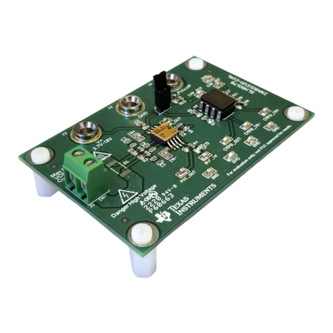
TPS54521 Step-Down Converter Evaluation Module User's
Guide
Table of Contents
1 Introduction.............................................................................................................................................................................3
1.1 Background........................................................................................................................................................................ 3
1.2 Performance Specification Summary.................................................................................................................................3
1.3 Modifications...................................................................................................................................................................... 4
2 Test Setup and Results.......................................................................................................................................................... 5
2.1 Input / Output Connections................................................................................................................................................ 5
2.2 Efficiency............................................................................................................................................................................6
2.3 Output Voltage Load Regulation........................................................................................................................................ 7
2.4 Output Voltage Line Regulation......................................................................................................................................... 7
2.5 Load Transients..................................................................................................................................................................8
2.6 Loop Characteristics.......................................................................................................................................................... 8
2.7 Output Voltage Ripple........................................................................................................................................................ 9
2.8 Input Voltage Ripple........................................................................................................................................................... 9
2.9 Powering Up.....................................................................................................................................................................10
2.10 Hiccup Overcurrent Mode Operation..............................................................................................................................11
2.11 Thermal Characteristics..................................................................................................................................................11
3 Board Layout.........................................................................................................................................................................13
3.1 Layout.............................................................................................................................................................................. 13
3.2 Estimated Circuit Area..................................................................................................................................................... 14
4 Schematic and Bill of Materials...........................................................................................................................................15
4.1 Schematic........................................................................................................................................................................ 15
4.2 Bill of Materials.................................................................................................................................................................17
5 Revision History................................................................................................................................................................... 17
List of Figures
Figure 2-1. TPS54521EVM-607 Efficiency.................................................................................................................................. 6
Figure 2-2. TPS54521EVM-607 Low Current Efficiency..............................................................................................................6
Figure 2-3. TPS54521EVM-607 Load Regulation....................................................................................................................... 7
Figure 2-4. TPS54521EVM-607 Line Regulation........................................................................................................................ 7
Figure 2-5. TPS54521EVM-607 Transient Response................................................................................................................. 8
Figure 2-6. TPS54521EVM-607 Loop Response........................................................................................................................ 8
Figure 2-7. TPS54521EVM-607 Output Ripple........................................................................................................................... 9
Figure 2-8. TPS54521EVM-607 Input Ripple.............................................................................................................................. 9
Figure 2-9. TPS54521EVM-607 Start-Up Relative to VIN .........................................................................................................10
Figure 2-10. TPS54521EVM-607 Start-Up Relative to Enable..................................................................................................10
Figure 2-11. TPS54521EVM-607 Overcurrent Hiccup Mode..................................................................................................... 11
Figure 2-12. TPS54521EVM-607 Thermal Image......................................................................................................................11
Figure 2-13. TPS54521EVM-607 Junction Temperature vs Load Current................................................................................ 12
Figure 3-1. TPS54521EVM-607 Top-Side Layout (Top View)....................................................................................................13
Figure 3-2. TPS54521EVM-607 Layer 2 (X-Ray Top View).......................................................................................................13
Figure 3-3. TPS54521EVM-607 Layer 3 (X-Ray Top View).......................................................................................................14
Figure 3-4. TPS54521EVM-607 Bottom-Side Layout (Bottom View)........................................................................................ 14
Figure 3-5. TPS54521EVM-607 Top-Side Assembly.................................................................................................................14
Figure 4-1. TPS54521EVM-607 Schematic...............................................................................................................................16
List of Tables
Table 1-1. Input Voltage and Output Current Summary...............................................................................................................3
Table 1-2. TPS54521EVM-607 Performance Specification Summary.........................................................................................3
Table 1-3. Output Voltages Available...........................................................................................................................................4
www.ti.com Table of Contents
SLVU379A – AUGUST 2010 – REVISED AUGUST 2021
Submit Document Feedback
TPS54521 Step-Down Converter Evaluation Module User's Guide 1
Copyright © 2021 Texas Instruments Incorporated
