Texas Instruments DLP LightCrafter Dual DLPC900 Instruction sheet
Other Texas Instruments Controllers manuals
Texas Instruments
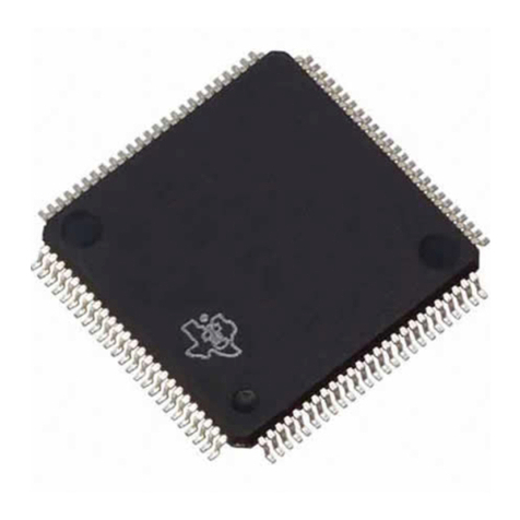
Texas Instruments TUSB2136 User manual
Texas Instruments
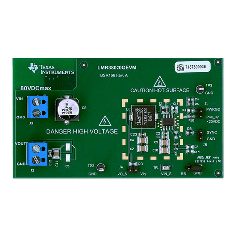
Texas Instruments LMR38020QEVM User manual
Texas Instruments
Texas Instruments TPS59640EVM-751 User manual
Texas Instruments
Texas Instruments TUSB422 EVM User manual
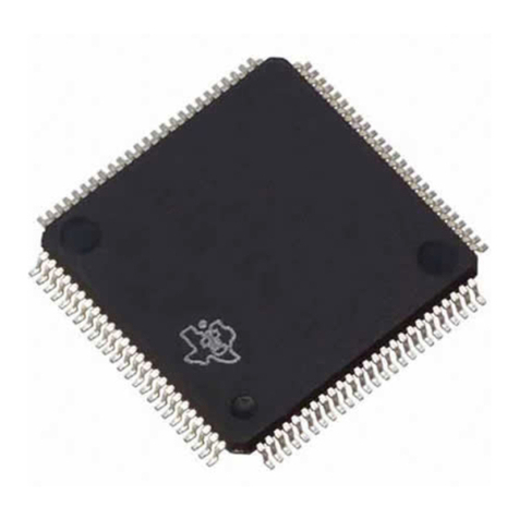
Texas Instruments
Texas Instruments TUSB5052 User manual
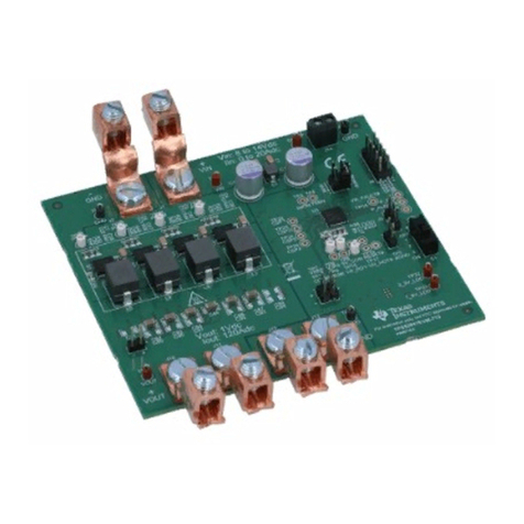
Texas Instruments
Texas Instruments TPS53647 User manual
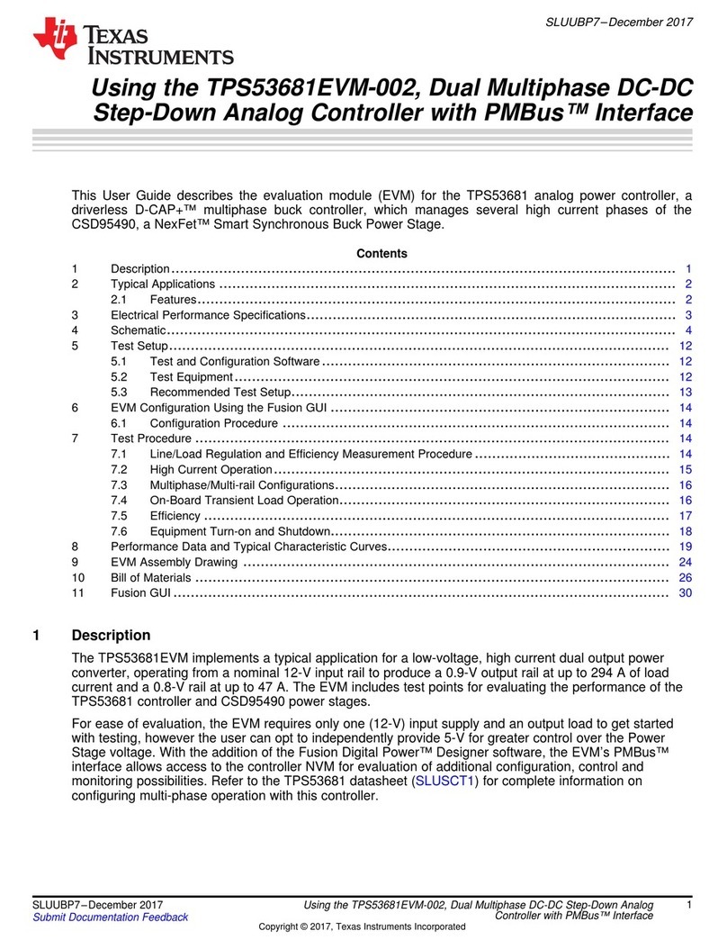
Texas Instruments
Texas Instruments TPS53681EVM-002 User manual
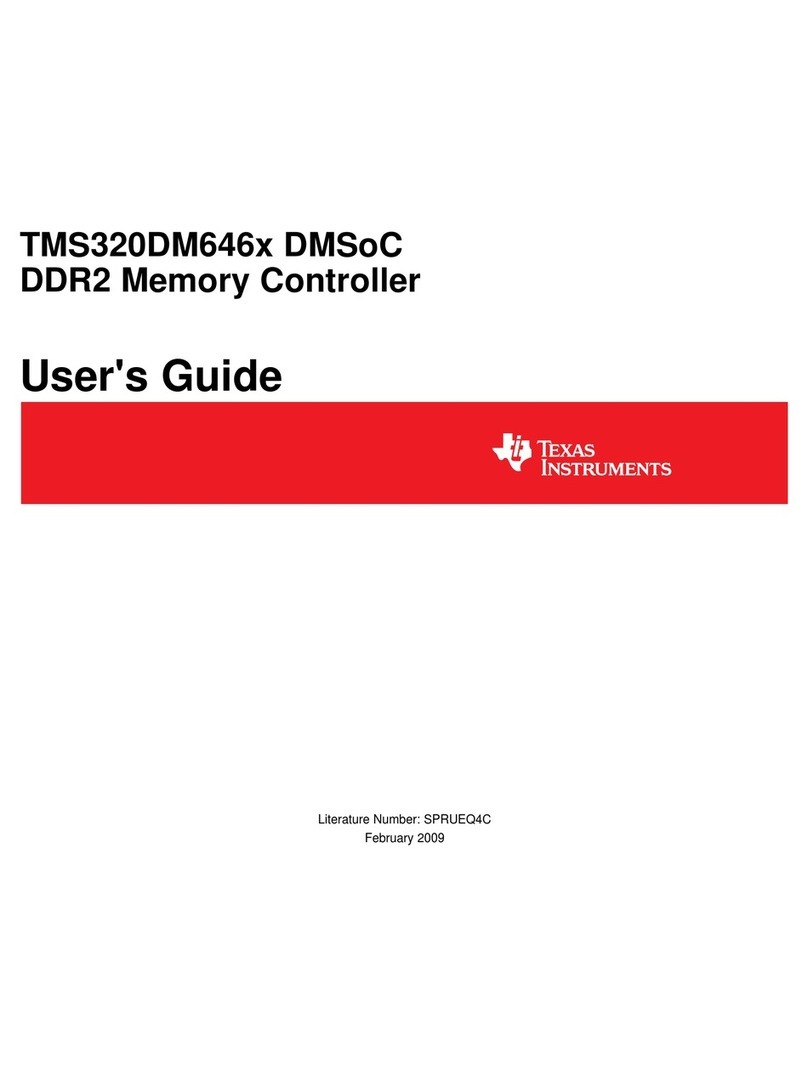
Texas Instruments
Texas Instruments TMS320DM646x User manual
Texas Instruments
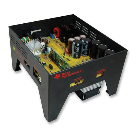
Texas Instruments TMDSHVMTRPFCKIT User manual
Texas Instruments
Texas Instruments TMS320C6000 DSP User manual
Texas Instruments
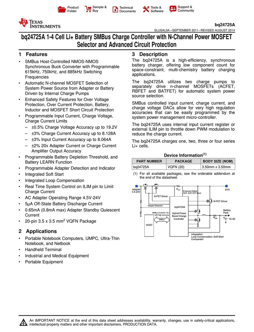
Texas Instruments bq24725A User manual
Texas Instruments
Texas Instruments TMS320DM644x User manual

Texas Instruments
Texas Instruments Sitara AM335x User manual
Texas Instruments
Texas Instruments TMS320C6747 DSP User manual
Texas Instruments
Texas Instruments LM4040A User manual
Texas Instruments
Texas Instruments TPS70351EVM User manual
Texas Instruments
Texas Instruments TMS320DM646 Series User manual
Texas Instruments
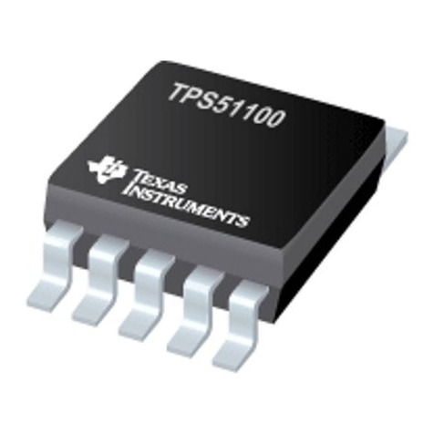
Texas Instruments TPS51100 User manual
Texas Instruments
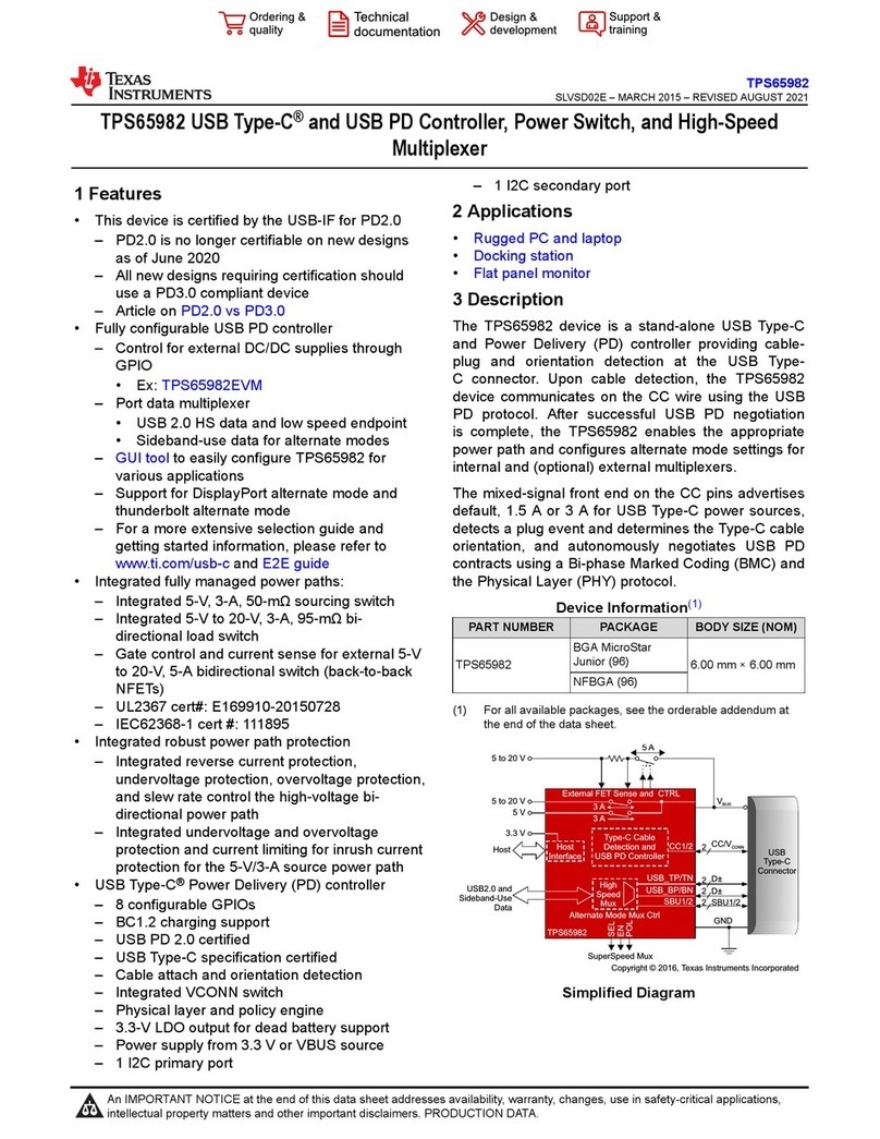
Texas Instruments TPS65982 User manual
Texas Instruments
Texas Instruments LM3429 User manual
Popular Controllers manuals by other brands

Digiplex
Digiplex DGP-848 Programming guide

YASKAWA
YASKAWA SGM series user manual

Sinope
Sinope Calypso RM3500ZB installation guide

Isimet
Isimet DLA Series Style 2 Installation, Operations, Start-up and Maintenance Instructions

LSIS
LSIS sv-ip5a user manual

Airflow
Airflow Uno hab Installation and operating instructions
