1
SLUUBA9A–June 2015–Revised February 2017
Submit Documentation Feedback Copyright © 2015–2017, Texas Instruments Incorporated
Using the TPS53647: PWR710-EVM, 4-Phase, D-CAP+ Step-Down, DC-DC
Analog with PMBus Interface
User's Guide
SLUUBA9A–June 2015–Revised February 2017
Using the TPS53647: PWR710-EVM, 4-Phase, D-CAP+
Step-Down, DC-DC Analog with PMBus Interface
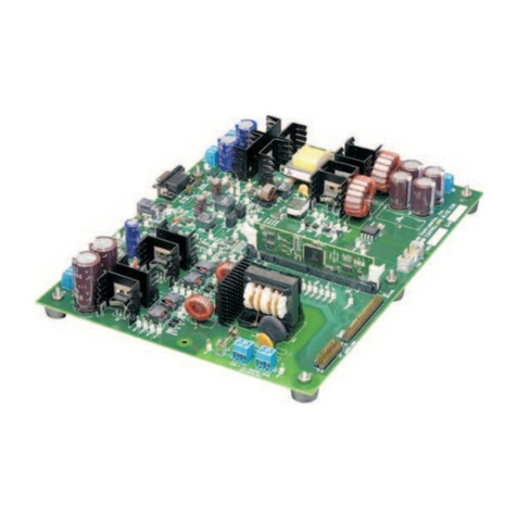
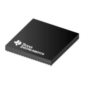
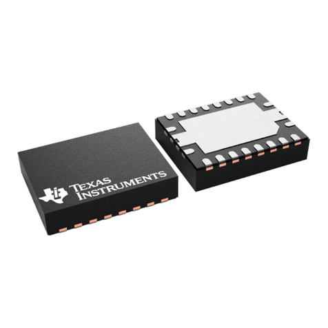
The PWR710-EVM evaluation module (EVM) uses the TPS53647 controller. The controller is 4-phase, D-
CAP+™ synchronous buck driverless controller with PMBus™ interface. The device operates using a
voltage supply between 4.5 V and 17 V. The controller allows programming and monitoring via the PMBus
interface. This PWR710-EVM uses the CSD95372B, Synchronous Buck NexFET™ Smart Power Stage
(SLPS499) device as the power stage.
Contents
1 Description.................................................................................................................... 1
1.1 Typical Applications ................................................................................................ 1
1.2 Features.............................................................................................................. 2
2 Electrical Performance Specifications..................................................................................... 2
3 Schematic..................................................................................................................... 3
4 Test Setup .................................................................................................................... 8
4.1 Test and Configuration Software ................................................................................. 8
4.2 Test Equipment ..................................................................................................... 8
4.3 Recommended Test Setup........................................................................................ 9
4.4 USB Interface Adapter and Cable .............................................................................. 10
4.5 List of Test Points and Connectors ............................................................................. 11
5 EVM Configuration Using the Fusion GUI .............................................................................. 13
5.1 Configuration Procedure ......................................................................................... 13
6 Test Procedure ............................................................................................................. 13
6.1 Line/Load Regulation and Efficiency Measurement Procedure............................................. 13
6.2 Control Loop Gain and Phase Measurement Procedure .................................................... 14
6.3 Efficiency ........................................................................................................... 14
6.4 Equipment Turn-on and Shutdown.............................................................................. 15
7 Performance Data and Typical Characteristic Curves................................................................. 16
8 EVM Assembly Drawing and PCB Layout .............................................................................. 19
9 List of Materials............................................................................................................. 22
10 Fusion GUI.................................................................................................................. 24
1 Description
The PWR710-EVM operates as a single output converter. The nominal 12-V bus produced a regulated,
1.0-V output at up to 120 A of load current. The PWR710-EVM demonstrates the controller in a typical
low-voltage high-current application while providing a number of test points to evaluate the performance of
the controller. Refer to TPS53647 (SLUSC39) datasheet for more information on multi-phase
configuration.
1.1 Typical Applications
• ASIC power in communications equipment
• High density power solutions
• Server power
• Smart power systems
