manuals.online logo
Brands
  1. Home
  2. •
  3. Brands
  4. •
  5. Texecom
  6. •
  7. Security Sensor
  8. •
  9. Texecom Prestige AMDT Plus User manual

Texecom Prestige AMDT Plus User manual

1 INTRODUCTION
QUALITY ASSURANCE
WARRANTY
10 year replacement warranty.
The Prestige AMDT Plus is designed to detect the movement of an intruder and
activate an alarm control panel. As the Prestige AMDT Plus is not a complete
alarm system, but only a part thereof, Texecom cannot accept responsibility or
liability for any damages whatsoever based on a claim that the Prestige AMDT
Plus failed to function correctly.
Due to our policy of continuous improvement Texecom reserves the right to change
specification without prior notice. All specifications are measured at 20ºC (68ºF).
© 2006 Texecom Ltd. Document Ref: PAMDT+/EU/1.0
The Prestige AMDT Plus is protected by UK & International Registered Designs.
Registered Design No’s: 3004997, 3004260 & 3004261. Prestige is a Trademark of Texecom Ltd.
Certificate Number: FM 35285
INS 317-2
www.texe.com
Ask your distributor today for the Texecom full colour Product Guide.
3.0m/9’10”
2.5m/8’2”
2.0m/6’7”
1.5m/4’11”
8 MOUNTING HEIGHT & SETTINGS7 TRIPLE END-OF-LINE (T-EOL)
The Prestige AMDT Plus is designed to be connected to a single zone on control
panels which feature Triple End-Of-Line (T-EOL) compatibility. Alarm, Tamper, Fault
and Masking are signalled on one pair of wires. To aid installation the resistor values
can be selected via the T-EOL plug-on board. All the connections are normally closed.
Masking is signalled by the alarm and fault relays opening simultaneously.
EOL ZONE
on control panel
TAMPER ALARM FAULT
T
AF
PANEL
PIR
Selectable T-EOL Resistors
Use the Option A T-EOL board with Texecom’s Premier range of
control panels.
Grade 3 Anti-Masking Dual Technology
INSTALLATION INSTRUCTIONS
MADE IN
ENGLAND
For use with the following Premier software versions (or above)
Premier 24: V7 Premier 412/816: V10
Premier 48: V7 Premier 832: V3
Premier 88/168: V7 Keypads: V7
Premier 640: V7 Expanders: V7
A range of other T-EOL values are available separately.
2 CHOOSING A LOCATION
Avoid common false alarm sources
3 MOUNTING
For indoor use only
✓
✗
✓
✗✓
Mount on a stable surface
5 WIRING
Do not run cable parallel to mains wiring
230V
110V
230V
110V
✓
✗
4 COVERAGE PATTERN
Volumetric
See Mounting Height Diagram (Section 8)
6 DETECTOR KNOCKOUTS
Rear tamper pull-out needs to be secured to
the mounting surface to meet Grade 3
requirements of TS50131-2-4
Rear tamper
pull-out
Fix both the detector
AND the rear tamper
pull-out to the wall.
DECLARATION OF CONFORMITY
1 2 3 4
ON
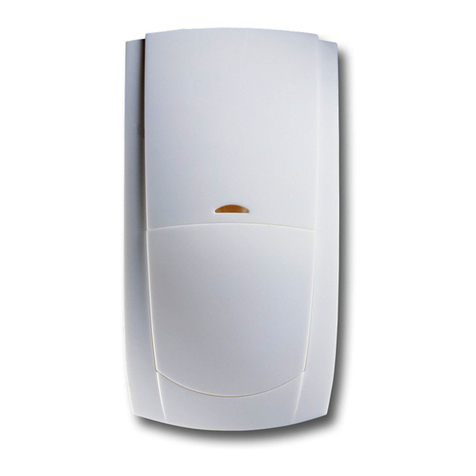
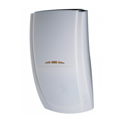
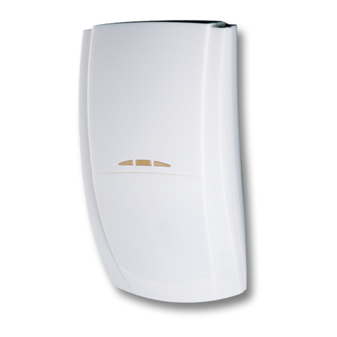
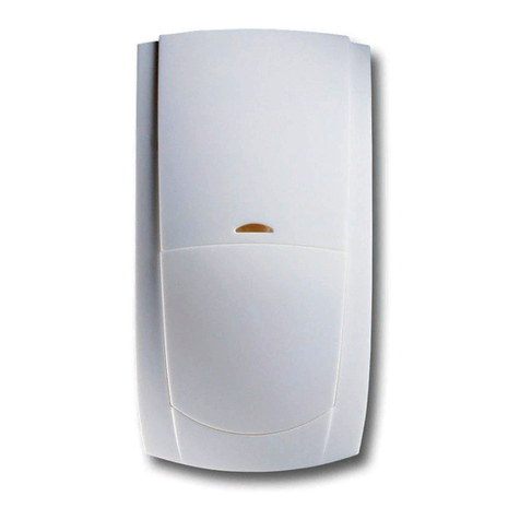
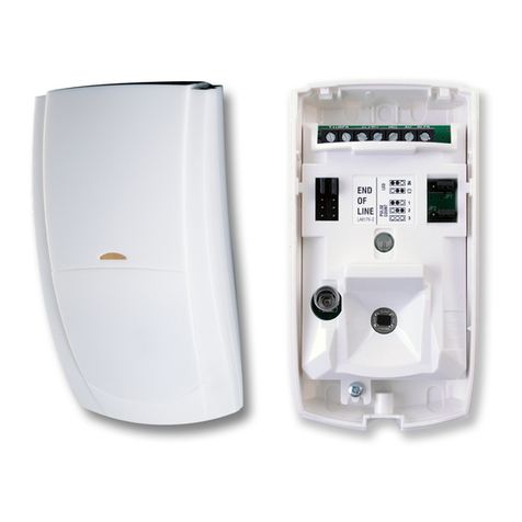
The Prestige AMDT Plus is a grade 3 anti-masking digital dual technology detector.
The combination of active IR and microwave proximity obstruction detection provides
unparalleled anti-masking reliability. Rear tamper protection, fault monitoring and Triple
End-Of-Line (T-EOL) signalling provide compliance with EN 50131-2-4.
Outstanding features include:
• 15m Volumetric PIR and Microwave Detection
• Active IR Anti-Masking
• Triple-End-Of-Line (T-EOL) Signalling
• Digital Microprocessor Technology
• Wall Tamper Detection
• Remote Self-Test Feature
1 2 3 4
ON
1 2 3 4
ON
This declaration is valid for the following product:
Device Type: Dual Technology Detector - DTD007-x
Product Name: Prestige DT/AMDT Plus
Equipment Classification: Short Range Device, Class 2
Notified Body Number: 0891
This is to confirm that this product meets all essential protection requirements relating to:
R&TTE Directive: 1999/05/EC
The assessment of this product has been based on the following standards:
EN 55022 : 1998 Emission Standard for Information Technology Equipment.
EN 50130-4 : 1996 Immunity Standard for Fire Intruder & Social Alarm Systems.
BS EN 60950-1 : 2002 Low Voltage Devices – Electrical Safety
ETSI EN 300 440-1 : 2001 Radio standard for short range devices (1GHz – 40GHz)
ETSI EN 301 489-3 : 2002 EMC standard for short range devices (9kHz – 40GHz)
On behalf of the manufacturer:
Texecom Ltd., 559 Wilbraham Road, Manchester, M21 0AE
This declaration is submitted by:
R J Austen, Managing Director
9th May 2006
9 ALTERING COVERAGE AT 2m
MOUNTING HEIGHT
INS 317-2
12 GRADE 3 ANTI-MASKING 14 LED FUNCTIONS
• The Prestige AMDT Plus is designed to meet both EN 50131-1 and
TS 50131-2-4 and as such is a future-proof solution.
• On either power-up or reapplication of the front cover the detector will
temporarily enter an auto-optimisation mode to adapt to it’s environment. This
will be shown by the LED’s flashing in sequence.
• During optimisation ensure that there are no obstructions in close proximity (<1m)
to the detector that will not be present during normal operation, as this could
trigger a false masking signal.
• During installation avoid mounting the detector where objects may interfere with
the anti-masking function (<1m), above doors, near curtains etc.
• The detector should not be mounted in direct sunlight.
• Masking is signalled by the fault and alarm relay opening simultaneously.
A fault will be indicated by one of the following:
• Supply input voltage out of specification
• PIR sensor malfunction
• Microwave sensor malfunction
The fault will be cleared once the condition has been resolved.
Self-Test
To meet the requirements of TS 50131-2-4 this detector is capable of performing a
self-test. There are two types of self-test; a local self-test and a remote self-test.
Local Self-Test
Local self-test is controlled by the detector and runs periodically to test the functionality
of the circuitry. Setting SW4 to off can disable this function. If the test is passed no
indication is shown but if it fails then a fault will be signalled to the panel and the orange
LED lit (if enabled). The fault will remain until a local or remote test is passed.
Remote Self-Test
This test is initiated at the control panel. If the test is passed then the detector will signal
an alarm. If the test fails then the detector will signal a fault. The fault will remain until a
local or remote test is passed. There is a dedicated control type for this output on Texecom
Premier panels, expanders and keypads for ease of installation. For more information on
setting up an output to run this test please see the relevant manual.
8m
26
'
2
"
10m
32
'
9
"
15m
50
'
15m
50
'
2m
6'7"
2m
6'7"
2m
6'7"
2m
6'7"
18 PHYSICAL
60mm
(2.4”)
40mm
(1.6”)
112.25mm
(4.4”)
2.5mm (0.1”) ABS
19 ENVIRONMENTAL
-35°C (-31°F) to +60°C (+140°F)
150g (5oz) approx.
-35°C (-31°F) to +55°C (+131°F)
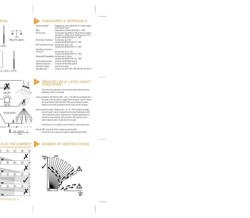
15 STANDARDS & APPROVALS
Detector Standard: TS 50131-2-4 Grade 3 Environmental Class II.
System Standard: Suitable for use in a PD 6662/BS EN 50131-1 Grade
3 system, Environmental Class II.
EMC: Independently certified to BS EN 50130-4 : 1996.
RF Immunity: No false alarms from 80MHz to 2GHz at 10V/m.
Complies with BS EN 61000-4-3 : 2002.
Electrostatic
Discharge:
No false alarms up to 8kV.
Complies with BS EN 61000-4-2 : 1995.
Fast Transient
Immunity:
No false alarms up to ±4kV.
Complies with BS EN 61000-4-4 : 1995.
High Energy
Transient Immunity:
No false alarms up to ±2kV.
Complies with BS EN 61000-4-5 : 1995.
Conducted RF
Susceptibility:
No false alarms at 10Vrms.
Complies with BS EN 61000-4-5 : 1995.
Conducted &
Radiated Emissions:
Complies with EN 55022 Class B.
Product Identifier: AMDT Plus
1 3 FAULT MONITORING
Detector Status LED Indication
Alarm: Both LED's Red
PIR Detection: Right LED Green
Microwave Detection: Left LED Orange
Masking: Left LED Flashing Green
Fault: Right LED Flashing Orange
Masking & Microwave Detection: Left LED Alternating Green and Orange
Fault And PIR Detection: Right LED Alternating Green and Orange
10 WIRING & DETECTOR SET-UP
1 2 3 4
ON
DO NOT
TOUCH
PULSE COUNT
5m
16'4"
2m
6
'
7
"
!
2m
6
'
7
"
15m
50'
2m
6
'
7
"
17 WALL MOUNT BRACKET *
2
2 41 3
1 3 4 5
5
16 CEILING MOUNT BRACKET *
11 DETECTOR SET-UP
0V = TEST
12V/NC = Unset
0V = Alert/Set
9-16VDC
19mA @ 12VDC
Triple End-Of-Line
Remote LED:
0V= 12V/NC=
INPUT FUNCTIONS:
RLED: 12V/No connection: LED’s will function in accordance with the setting of SW2
0V: LED’s will not function even if they are enabled via SW2
SET: 12V/No connection: Detector is in the Standby/unset mode
0V: Detector is in the Alert/set mode
TEST: 12V/No connection: Normal operation
0V: Initiate remote self-test
*Not for use in a Grade 3 system

Other Texecom Security Sensor manuals

Texecom Premier External TD-W User manual

Texecom

Texecom Premier External TD-W User manual

Texecom Prestige IR User manual

Texecom

Texecom Prestige IR User manual

Texecom Capture P15-W User manual

Texecom

Texecom Capture P15-W User manual

Texecom Premier Elite CO-W User manual

Texecom

Texecom Premier Elite CO-W User manual

Texecom Prestige Orbit QD User manual

Texecom

Texecom Prestige Orbit QD User manual

Texecom Premier Elite MR Long Range User manual

Texecom

Texecom Premier Elite MR Long Range User manual

Texecom Impaq SC-W User manual

Texecom

Texecom Impaq SC-W User manual

Texecom Premier Elite XT-W User manual

Texecom

Texecom Premier Elite XT-W User manual

Texecom Premier Elite AMQD User manual

Texecom

Texecom Premier Elite AMQD User manual

Texecom Premier 360 DT User manual

Texecom

Texecom Premier 360 DT User manual

Texecom Capture A20 User manual

Texecom

Texecom Capture A20 User manual

Texecom AED-0009 User manual

Texecom

Texecom AED-0009 User manual

Texecom Premier Elite AM 360DT User manual

Texecom

Texecom Premier Elite AM 360DT User manual

Texecom Odyssey Series User manual

Texecom

Texecom Odyssey Series User manual

Texecom Premier Elite DT-W User manual

Texecom

Texecom Premier Elite DT-W User manual

Texecom Premier Elite Impaq Plus-W User manual

Texecom

Texecom Premier Elite Impaq Plus-W User manual

Texecom Reflex User manual

Texecom

Texecom Reflex User manual

Texecom Premier Elite ComWiFi User manual

Texecom

Texecom Premier Elite ComWiFi User manual

Texecom Prestige DT User manual

Texecom

Texecom Prestige DT User manual

Texecom Premier Elite AM360 QD User manual

Texecom

Texecom Premier Elite AM360 QD User manual

Texecom CAPTURE P15 User manual

Texecom

Texecom CAPTURE P15 User manual

Texecom Veritas Reflex INS156-7 User manual

Texecom

Texecom Veritas Reflex INS156-7 User manual

Texecom Premier Elite Impaq Plus-W User manual

Texecom

Texecom Premier Elite Impaq Plus-W User manual

Texecom Mirage DT Petwise User manual

Texecom

Texecom Mirage DT Petwise User manual

Popular Security Sensor manuals by other brands

RKI Instruments 35-3001-01H Operator's manual

RKI Instruments

RKI Instruments 35-3001-01H Operator's manual

Dyacon LD-1 manual

Dyacon

Dyacon LD-1 manual

VOLTCRAFT LSG-4 operating instructions

VOLTCRAFT

VOLTCRAFT LSG-4 operating instructions

Teletek electronics SensoIRIS GAS manual

Teletek electronics

Teletek electronics SensoIRIS GAS manual

BEA WIZARD II SMR user guide

BEA

BEA WIZARD II SMR user guide

MS Sedco DHR3 installation instructions

MS Sedco

MS Sedco DHR3 installation instructions

bolid S2000-IK Rev.03 instruction manual

bolid

bolid S2000-IK Rev.03 instruction manual

UniPOS FD 7110 instruction manual

UniPOS

UniPOS FD 7110 instruction manual

PRO Intellect Technology MONIRON DEC EUR user manual

PRO Intellect Technology

PRO Intellect Technology MONIRON DEC EUR user manual

Technoalarm Global Space Bus quick start guide

Technoalarm

Technoalarm Global Space Bus quick start guide

Sunell SN-D2-F user manual

Sunell

Sunell SN-D2-F user manual

Vimar By-alarm 01727.1 manual

Vimar

Vimar By-alarm 01727.1 manual

JUMO ZELOS operating manual

JUMO

JUMO ZELOS operating manual

Optex FX-50QZ installation instructions

Optex

Optex FX-50QZ installation instructions

R&TTE CC-400 instruction manual

R&TTE

R&TTE CC-400 instruction manual

Bircher Reglomat PrimeTec B Original instructions

Bircher Reglomat

Bircher Reglomat PrimeTec B Original instructions

Kanlux DECK CO quick start guide

Kanlux

Kanlux DECK CO quick start guide

Vision VIS ZS6301 quick start

Vision

Vision VIS ZS6301 quick start

manuals.online logo
manuals.online logoBrands
  • About & Mission
  • Contact us
  • Privacy Policy
  • Terms and Conditions

Copyright 2025 Manuals.Online. All Rights Reserved.