manuals.online logo
Brands
  1. Home
  2. •
  3. Brands
  4. •
  5. Thermo King
  6. •
  7. Automobile Accessories
  8. •
  9. Thermo King Spectrum TS User manual

Thermo King Spectrum TS User manual

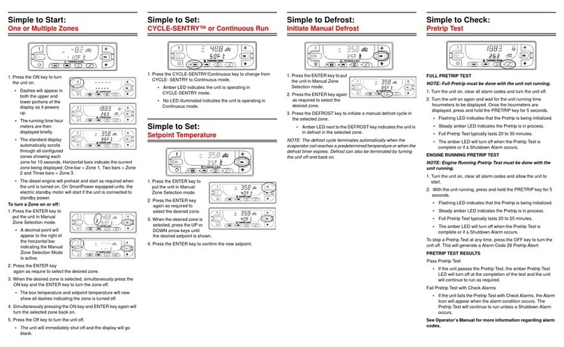
7XUQ8QLW2QRU2II
6WDQGDUG'LVSOD\
6HOHFW=RQH'LVSOD\
7XUQ=RQH2QRU2II
&KDQJH=RQH6HWSRLQW
6WDUW(QJLQH
,QLWLDWH0DQXDO'HIURVW
+LJK6SHHG/RF RXW
2
3
1. Press the ON Key. TK logo is shown briefly.
2. Startup screen appears. Unit prepares to operate.
3. Standard Display indicates unit is ready to run.
4
4. Press OFF key to stop unit operation.
Screen will display OFF, then go blank.
1
Standard Display
is the default
when no other
display function is
selected. Shows box temperature and setpoint or
OFF for all zones. Two zone operation shown
here. Zone 1 is – 9.4 F with –10 F setpoint. Zone 2
is 35.8 F with 35 F setpoint. Top of display shows
unit is in CYCLE SENTRY mode. Two arrows
indicate that both zones are cooling.
1. At the Standard Display, press the soft key to
show the Zone Display for the desired zone.
1
2
2. Selected zone is displayed.
3. “Turn Zone (number) ON/OFF” identifies zone
and indicates that zone may turned ON (if
presently off) or OFF (if presently on).
3
1. At the Standard Display, press the soft key to
show the Zone Display for the desired zone.
1
2
2. Turn Zone ON or OFF by pressing soft key.
3. Display will briefly indicate change in progress.
3
4. Display will show new zone setting, then return to
Standard Display after 30 seconds.
4
1. At the Standard Display, press the soft key to show
Zone Display for the desired zone (Zone 2 shown
).
2. Press the “-” and/or “+” soft keys to display
setpoint. YES and NO soft keys also appear. “-
” and/or “+” soft keys are used to change setpoint
(here to 40 F).
4
1
2
3. When desired setpoint is reached, press YES sof
t
key within 10 seconds to confirm and load
3
4. Display will briefly show “PROGRAMMING NEW
SETPOINT”, then return to the Standard Display.
Diesel engine preheats and starts are automatic in
Continuous and CYCLE SENTRY modes. The
engine will preheat and start as necessary if the uni
t
is on. The start screen will be displayed. Preheat an
d
start will be delayed in CYCLE SENTRY if there is n
o
need for the unit to run.
Caution: The engine may start automaticall
y
at any time the unit is turned on.
Defrost cycles are usually initiated based on time or
demand. Manual defrost is available if the zone is on
and the coil temperature is less than 45 F (7 C). Only
one zone may be defrosted at a time.
1. Press the DEFROST key. The display will prompt
for the zone to defrost
2. Press the soft key to select the zone to defrost.
Defrost of that zone will begin (Zone 1 shown here
).
1
2
3
3. The display will briefly show “PROGRAMMING
DEFROST” and then “ZONE ‘X’ DEFROST
STARTED” where X = zone1 or 2.
4. Display will return to Standard Display. The zone
in defrost will show “DEF.” Bar indicator shows
approximated time to complete defrost cycle.
If preprogrammed, high speed operation can be
locked out. Press the key to enable or disable the
feature. Display shows lockout programming in
progress and then active or inactive status.
9LHZLQJ&OHDULQJ$ODUP&RGHV 9LHZLQJ+RXUPHWHUV
&<&/(6(175<RU&RQWLQXRXV
(FRQRP\0RGH
'LHVHORU(OHFWULF2SHUDWLRQ
63(&758076
0XOWL7HPS
&RQWURO6\VWHP
2SHUDWLQJ*XLGH
+0,&RQWURO3DQHO)HDWXUHV
2. Alarms are displayed and cleared with the
Alarm Menu. From the Standard Display press
the MENU key.
1
2
Language or Alarm Menu will appear. If “LANGUAGE”
appears, press the NEXT key to show Alarm Menu.
4. Alarm display will appear. If no alarms are present,
NO ALARMS will appear. If alarms are present,
quantity of alarms and most recent alarm code will
be shown. If the alarm pertains to a specific zone,
that zone will be identified.
3
4
1. If an alarm condition occurs, an alarm message
appears in place of the mode indication.
3. Press the SELECT key.
5. After the alarm is resolved, press the CLEAR key
to clear the alarm. For information on the alarm,
press the HELP key. To display the next alarm,
press the NEXT key. Press EXIT to return to the
Standard Display.
5
If a serious condition occurs, the unit will shut down
to prevent damage. The display will indicate unit
shutdown and the alarm code which caused it. A
complete list of alarm codes can be found in the
unit Operators Manual or Maintenance Manual.
1. From the Standard Display, press the MENU key.
The Language or Alarm Menu will appear. Press
the NEXT key display the Hourmeter Menu.
2. Press the SELECT key to see Hourmeter Display.
1
2
3
3. Press the NEXT or PREVIOUS key to scroll
through the hourmeters.
1. From the Standard Display, press the MENU key.
The Language or Alarm Menu will appear. Press
the NEXT key display the MODE Menu.
2. Press SELECT key to change mode between
CYCLE SENTRY and Continuous. Display will
confirm change in progress and resulting mode.
Display then returns to Mode Menu.
1
2
CYCLE SENTRY mode causes unit to start and stop
automatically to maintain compartment setpoint, keep
engine warm and battery charged. Continuous mode
starts and runs unit continuously to maintain setpoint
and constant airflow.
From the Standard Display, press the MENU key.
The Language or Alarm Menu will appear. Press the
NEXT key as required to display Economy Mode.
1. Press the SELECT key to turn Economy Mode on
.
1
2
Economy Mode can be used for loads that do not
require critical temperature control.
2. The display will confirm the change, show new
mode for 10 seconds, then return to Mode Menu
.
Economy Mode can be turned off by pressing the
SELECT key again.
1. If unit is turned on while connected to electric
power, Electric Standby screen will be displayed
for 10 seconds. Unit will run normally.
1
2
Factory-set default is for automatic changeover to
Electric Mode when the unit is connected to electric
power. Unit will switch back to Diesel power if
electric power fails or is disconnected.
2. If unit is turned on in Electric Standby Mode and
electric power is not available, prompt will be show
n.
Switch to Diesel Mode by pressing YES key.
1235
7
4
6
1. ON Key
2. OFF Key
3. Multi-Purpose “Soft” Keys
4. Manual Defrost Key
5. High Speed Lockout Key
6. Zone 1 Display
7. Zone 2 Display
TK 52145-1-PC (Rev. 1, 08/03)
CAUTION: This is a quick reference guide.
Always refer to the operating manual for
detailed instructions.
Other Thermo King Automobile Accessories manuals

Thermo King E-200 User manual

Thermo King

Thermo King E-200 User manual

Thermo King VCP2 User manual

Thermo King

Thermo King VCP2 User manual

Thermo King V220 Series User manual

Thermo King

Thermo King V220 Series User manual

Thermo King Smart Reefer 3 Installation and operation manual

Thermo King

Thermo King Smart Reefer 3 Installation and operation manual

Thermo King UT-800 User manual

Thermo King

Thermo King UT-800 User manual

Thermo King T- series User manual

Thermo King

Thermo King T- series User manual

Thermo King T- series User manual

Thermo King

Thermo King T- series User manual

Thermo King 42-2499 Reference guide

Thermo King

Thermo King 42-2499 Reference guide

Thermo King T-1000R User manual

Thermo King

Thermo King T-1000R User manual

Thermo King Precedent S-750i User manual

Thermo King

Thermo King Precedent S-750i User manual

Thermo King Whisper User manual

Thermo King

Thermo King Whisper User manual

Thermo King V-520 RT Series User manual

Thermo King

Thermo King V-520 RT Series User manual

Thermo King SLXi-100 User manual

Thermo King

Thermo King SLXi-100 User manual

Thermo King B Series User manual

Thermo King

Thermo King B Series User manual

Thermo King Precedent C-600M User manual

Thermo King

Thermo King Precedent C-600M User manual

Thermo King V Series User manual

Thermo King

Thermo King V Series User manual

Thermo King V-520 Series User manual

Thermo King

Thermo King V-520 Series User manual

Thermo King B-100 User manual

Thermo King

Thermo King B-100 User manual

Thermo King V220 Series User manual

Thermo King

Thermo King V220 Series User manual

Thermo King TriPac EVOLUTION User manual

Thermo King

Thermo King TriPac EVOLUTION User manual

Popular Automobile Accessories manuals by other brands

Toyota AVENSIS -  S installation instructions

Toyota

Toyota AVENSIS - S installation instructions

Directed DIRECTECHS HONDA4 installation guide

Directed

Directed DIRECTECHS HONDA4 installation guide

Prorack K319 Fitting instructions

Prorack

Prorack K319 Fitting instructions

Prorack K1214 instructions

Prorack

Prorack K1214 instructions

Westfalia 95 75 87 Original instructions

Westfalia

Westfalia 95 75 87 Original instructions

Cruz Alu-Rack L 13-120 Assembly instructions

Cruz

Cruz Alu-Rack L 13-120 Assembly instructions

Yakima K618 instructions

Yakima

Yakima K618 instructions

Bully Dog PMT installation manual

Bully Dog

Bully Dog PMT installation manual

ADAPT SOLUTIONS SPEEDY-LIFT SP-HDA05 installation manual

ADAPT SOLUTIONS

ADAPT SOLUTIONS SPEEDY-LIFT SP-HDA05 installation manual

Logo Lites 100-005/K installation guide

Logo Lites

Logo Lites 100-005/K installation guide

Whelen Engineering Company GEKT98LP installation guide

Whelen Engineering Company

Whelen Engineering Company GEKT98LP installation guide

DreamGEAR ROAD TALK datasheet

DreamGEAR

DreamGEAR ROAD TALK datasheet

HAUL MASTER 96349 Set up and operating instructions

HAUL MASTER

HAUL MASTER 96349 Set up and operating instructions

Diehl IZAR RDC VEHICLE user guide

Diehl

Diehl IZAR RDC VEHICLE user guide

EUFAB 16472 operating instructions

EUFAB

EUFAB 16472 operating instructions

Metra Electronics 99-3400 installation instructions

Metra Electronics

Metra Electronics 99-3400 installation instructions

Gamber Johnson 7160-1295 installation instructions

Gamber Johnson

Gamber Johnson 7160-1295 installation instructions

Guardsman G1341 Fitting instructions

Guardsman

Guardsman G1341 Fitting instructions

manuals.online logo
manuals.online logoBrands
  • About & Mission
  • Contact us
  • Privacy Policy
  • Terms and Conditions

Copyright 2025 Manuals.Online. All Rights Reserved.