TLV QuickTrap FS Series User manual

Copyright (C) 2018 by TLV CO., LTD. All rights reserved.
F46+F32
FS SERIES
FS SERIE
GAMME FS
FREE FLOAT TYPE STEAM TRAPS
FREISCHWIMMER-KONDENSATABLEITER
PURGEURS DE VAPEUR À FLOTTEUR FERMÉ LIBRE
QuickTrap
FS3/FS5/FS5H
Trap Unit
S3/S5/S5H
操作说明书
请务必妥善保管此说明书,以备日后使用。
自由浮球式蒸汽疏水阀
FS系列
INSTRUCTION MANUAL
Keep this manual in a safe place for future reference
EINBAU- UND BETRIEBSANLEITUNG
Gebrauchsanleitung leicht zugänglich aufbewahren
MANUEL D UTILISATION
Conserver ce manuel dans un endroit facile d'accès
Option
BD2
( )
Deutsch
Français
English
中 文

Introduction
Before you begin, please read this manual to ensure correct usage of the product, and keep it in
a safe place for future reference.
The FS3/FS5/FS5H steam traps (trap units S3/S5/S5H and connector unit F46 or former
connector unit F32*), designed for installation in any inclination, are suitable for small and medium
capacity applications between 0.01 and 4.6 MPaG (1 and 650 psig); such as saturated and
superheated steam mains, branches, tracer lines and small-to-medium size process equipment.
The traps discharge condensate continuously and automatically at a temperature slightly lower
than saturation temperature.
* Configuration of F32 differs slightly from that of F46
1 MPa = 10.197 kg/cm2, 1 bar = 0.1 MPa
For products with special specifications or with options not included in this manual, contact TLV
for instructions.
The contents of this manual are subject to change without notice.
Einführung
Bitte lesen Sie die Betriebsanleitung vor Einbau und Inbetriebnahme sorgfältig durch und be-
wahren Sie sie für späteren Gebrauch an einem leicht zugänglichen Ort auf.
Die “Freischwimmer” Kondensatableiter FS3/FS5/FS5H (Kondensatableiter S3/S5/S5H sowie
Universalanschlussstück F46 bzw. älteres Universalanschlussstück F32*) für beliebige Einbaulage
ermöglichen die automatische und kontinuierliche Ableitung kleinerer bis mittlerer
Kondensatmengen zwischen 0,1 und 46 bar ü, auch im überhitzten Bereich. Sie sind besonders
geeignet für Leitungsentwässerung, Begleitheizung und Prozesse, bei denen Kondensat mit
geringer Unterkühlung unter Sattdampftemperatur abgeleitet werden soll.
* Formgebung von F32 weicht von F46 etwas ab
1 bar = 0,1 MPa
Wenden Sie sich an TLV für Sonderausführungen, die nicht in dieser Einbau- und Betriebs-
anleitung enthalten sind.
Wir behalten uns vor, den Inhalt dieser Betriebsanleitung ohne Ankündigung zu ändern.
Introduction
Veuillez lire attentivement ce manuel afin d'utiliser correctement le produit.
Nous vous recommandons de le garder dans un endroit sûr pour de futures consultations.
Les purgeurs de vapeur FS3/FS5/FS5H (purgeur S3/S5/S5H et unité de raccord F46 ou la
précédente F32*) conviennent pour les applications de petite à moyenne capacité entre 0,1 et 46
bar, telles les conduites et tubulures de vapeur saturée ou surchauffée, les lignes de traçage et
les appareillages de process légers. Ces purgeurs évacuent le condensât de manière continue et
automatique, à une température légèrement inférieure à la température de saturation. Ils peuvent
être installés dans n'importe quelle position.
* La construction de la F32 diffère légèrement de celle de la F46
1 bar = 0,1 MPa
Pour tout produit aux spécifications particulières ou comportant des options non reprises dans ce
manuel, veuillez contacter TLV.
Le contenu de ce manuel est sujet à modifications sans préavis.
1
Deutsch
Français
English

English
1. Safety Considerations
―2―
• Read this section carefully before use and be sure to follow the instructions.
• Installation, inspection, maintenance, repairs, disassembly, adjustment and valve
opening/closing should be carried out only by trained maintenance personnel.
• The precautions listed in this manual are designed to ensure safety and prevent equipment
damage and personal injury. For situations that may occur as a result of erroneous handling,
three different types of cautionary items are used to indicate the degree of urgency and the
scale of potential damage and danger: DANGER, WARNING and CAUTION.
• The three types of cautionary items above are very important for safety; be sure to observe
all of them, as they relate to installation, use, maintenance, and repair. Furthermore, TLV
accepts no responsibility for any accidents or damage occurring as a result of failure to
observe these precautions.
Indicates an urgent situation
which poses a threat of
death or serious injury.
Indicates that there is a
potential threat of death
or serious injury.
WARNING
CAUTION
WARNING
DANGER CAUTION
Indicates that there is a
possibility of injury or equip-
ment/product damage.
NEVER apply direct heat to the float. The float may explode due to
increased internal pressure, causing accidents leading to serious injury
or damage to property and equipment.
Install properly and DO NOT use this product outside the recommended
operating pressure, temperature and other specification ranges.
Improper use may result in such hazards as damage to the product or
malfunctions, which may lead to serious accidents. Local regulations may
restrict the use of this product to below the conditions quoted.
Take measures to prevent people from coming into direct contact
with product outlets. Failure to do so may result in burns or other injury
from the discharge of fluids.
DO NOT use this product in excess of the maximum operating pressure
differential. Such use could make discharge impossible (blocked).
When disassembling or removing the product, wait until the internal
pressure equals atmospheric pressure and the surface of the
product has cooled to room temperature. Disassembling or removing
the product when it is hot or under pressure may lead to discharge of
fluids, causing burns, other injuries or damage.
Be sure to use only the recommended components when repairing
the product, and NEVER attempt to modify the product in any way.
Failure to observe these precautions may result in damage to the product
or burns or other injury due to malfunction or the discharge of fluids.
Do not subject the trap to condensate loads that exceed its
discharge capacity. Failure to observe this precaution may lead to
condensate accumulation upstream of the trap, resulting in reduced
equipment performance or damage to the equipment.
Use only under conditions in which no freeze-up will occur. Freezing
may damage the product, leading to fluid discharge, which may cause
burns or other injury.
Use under conditions in which no water hammer will occur. The
impact of water hammer may damage the product, leading to fluid
discharge, which may cause burns or other injury.
The pressure and temperature values displayed on the nameplate of
the connector body are the values for the connector body itself and
not for the entire trap. Improper use may result in such hazards as
damage to the product or malfunctions that may lead to serious accidents.

1. Sicherheitshinweise
• Bitte lesen Sie dieses Kapitel vor Beginn der Arbeiten sorgfältig durch und befolgen Sie die
Vorschriften.
• Einbau und Ausbau, Inspektion, Wartungs-und Reparaturarbeiten, Öffnen/Schließen von
Armaturen, Einstellung von Komponenten, dürfen nur von geschultem Wartungspersonal
vorgenommen werden.
• Die Sicherheitshinweise in dieser Einbau- und Betriebsanleitung dienen dazu, Unfälle,
Verletzungen, Betriebsstörungen und Beschädigungen der Anlagen zu vermeiden.
Für Gefahrensituationen, die durch falsches Handeln entstehen können, werden drei
verschiedene Warnzeichen benutzt: GEFAHR; WARNUNG; VORSICHT.
• Diese drei Warnzeichen sind wichtig für Ihre Sicherheit. Sie müssen unbedingt beachtet werden,
um den sicheren Gebrauch des Produktes zu gewährleisten und Einbau, Wartung und
Reparatur ohne Unfälle oder Schäden durchführen zu können. TLV haftet nicht für Unfälle oder
Schäden, die durch Nichtbeachtung dieser Sicherheitshinweise entstehen.
Bedeutet, dass eine unmittel-
bare Gefahr für Leib und
Leben besteht.
Bedeutet, dass die
Möglichkeit der Gefahr für
Leib und Leben besteht.
VORSICHT
WARNUNG
GEFAHR
WARNUNG
VORSICHT
Bedeutet, dass die Möglichkeit
von Verletzungen oder Schäden an
Anlagen oder Produkten besteht.
Die Schwimmerkugel darf NICHT ERHITZT werden, da sie infolge
erhöhten Innendruckes platzen kann, was schwere Unfälle und
Verletzungen oder Beschädigung von Anlagen zur Folge hat.
Die Einbauhinweise beachten und die spezifizierten Betriebsgrenzen
NICHT ÜBERSCHREITEN. Nichtbeachtung kann zu Betriebsstörungen
oder Unfällen führen. Lokale Vorschriften können zur Unterschreitung der
angegebenen Werte zwingen.
In sicherer Entfernung von Auslassöffnungen aufhalten und andere
Personen warnen, sich fernzuhalten. Nichtbeachtung kann zu
Verletzungen durch austretende Fluide führen.
Die auf dem Typenschild des Universalanschlussstücks angezeigten
Druck- und Temperaturwerte beziehen sich nur auf das
Universalanschlusstück, nicht auf die gesamte Ableitereinheit.
Unsachgemäße Verwendung kann zu Betriebsstörungen führen, welche
Beschädigungen des Produkts oder schwere Unfälle zur Folge haben
können.
Nur in frostsicherer Umgebung einsetzen. Einfrieren kann das Produkt
beschädigen, was zu Verbrennungen oder Verletzungen durch
austretende Fluide führt.
Nur an Stellen einbauen, an denen kein Wasserschlag eintreten
kann. Wasserschlag kann das Produkt beschädigen und zu
Verbrennungen oder Verletzungen durch austretende Fluide führen.
Das Produkt nicht bei Durchsatzmengen über der Nenn-
durchsatzleistung betreiben. Nichtbeachtung kann zu Kondensatrück-
stau führen wodurch die Leistung der Anlage beeinträchtigt, oder deren
Beschädigung verursacht wird.
Maximalen Differenzdruck NICHT ÜBERSCHREITEN,
da sonst die Kondensatableitung unmöglich werden kann (Blockage).
Vor Öffnen des Gehäuses und Ausbau von Teilen warten, bis der
Innendruck sich auf Atmosphärendruck gesenkt hat und das
Gehäuse auf Raumtemperatur abgekühlt ist. Nichtbeachtung kann zu
Verbrennungen oder Verletzungen durch austretende Fluide führen.
Zur Reparatur nur Original-Ersatzteile verwenden und NICHT
VERSUCHEN, das Produkt zu verändern. Nichtbeachtung kann zu
Beschädigungen führen, die Betriebsstörungen, Verbrennungen oder
andere Verletzungen durch austretende Fluide verursachen.
Deutsch
―3―

1. Règles de sécurité
• Lire attentivement cette notice avant l'utilisation et suivre les instructions.
• Tout installation, inspection, entretien, réparation, démontage, ajustement et
ouverture/fermeture de vanne doit être fait uniquement par une personne formée à l’entretien.
• La liste des précautions à prendre est établie afin d'assurer votre sécurité et de prévenir des
dégâts matériels et/ou des blessures sérieuses. Dans certaines situations causées par une
mauvaise manipulation, trois indicateurs sont utilisés afin d'indiquer le degré d'urgence,
l'échelle du dommage potentiel et le danger : DANGER, AVERTISSEMENT et ATTENTION.
• Ces 3 indicateurs sont importants pour votre sécurité ; observez les précautions de sécurité
énumérées dans ce manuel pour l'installation, l'utilisation, l'entretien et la réparation du produit.
TLV n'accepte aucune responsabilité en cas d'accident ou de dommage survenant à la suite
d'un non-respect de ces précautions.
Indique une situation
d'urgence avec risque de
mort ou de blessure grave.
Indique une situation
pouvant entraîner la mort ou
des blessures graves.
AVERTISSEMENT
ATTENTION
AVERTISSEMENT
DANGER
ATTENTION
Indique un risque de blessure
ou de dégât matériel au
produit et/ou aux installations.
Installer le produit correctement et NE PAS l’utiliser en dehors de la
pression et de la température maximales de fonctionnement, ni en
dehors des autres plages spécifiées. Une telle utilisation peut entraîner
des dommages au produit ou des dysfonctionnements, ce qui peut
provoquer des brûlures ou autres blessures. Il se peut que des règlements
locaux limitent l'utilisation du produit en-deçà des spécifications indiquées.
NE JAMAIS appliquer de chaleur directe au flotteur. Le flotteur pourrait
exploser suite à une pression interne accrue et causer des accidents
pouvant entraîner des blessures sérieuses ou des dégâts matériels.
Prendre les mesures appropriées afin d’éviter que des personnes
n’entrent en contact direct avec les ouvertures du produit. Le non-
respect de cette règle peut provoquer des brûlures ou autres blessures
sérieuses dues à l'écoulement des fluides.
Ne pas soumettre le purgeur à des charges de condensât
supérieures à sa capacité d'expulsion. Le non-respect de cette consigne
peut engendrer une accumulation de condensât en amont du purgeur et
réduire les performances des installations, voire les endommager.
En cas de démontage ou de manipulation du produit, attendre que
la pression interne soit égale à la pression atmosphérique et que la
surface du produit soit complètement refroidie. Le non-respect de
cette règle peut provoquer des brûlures ou autres dommages dus à
l'écoulement des fluides.
En cas de réparation, utiliser uniquement les composants
spécifiques du produit et NE JAMAIS ESSAYER de modifier le
produit. Le non-respect de cette règle peut entraîner des dommages au
produit, ou des brûlures et autres blessures sérieuses dues au
dysfonctionnement du produit ou à l'écoulement des fluides.
N’utiliser que dans des conditions où le gel ne se produit pas. Le gel
peut endommager le produit et provoquer l'écoulement des fluides, et
causer des brûlures ou autres blessures sérieuses.
Utiliser le produit dans des conditions où il n'y a aucun coup de
bélier. L'impact d'un coup de bélier peut endommager le produit et
provoquer l’écoulement des fluides, ainsi que des brûlures ou des
blessures graves.
NE PAS utiliser ce produit avec une pression différentielle
supérieure au maximum indiqué. Le non-respect de cette consigne
pourrait empêcher toute expulsion du condensât (blocage).
Les valeurs de pression et de température inscrites sur la plaquette
apposée sur l'unité de raccord correspondent aux caractéristiques
de l'unité de raccord elle-même et non pas à celles du purgeur. La
mauvaise utilisation de ce produit pourrait entrainer certains risques tels
que des dommages au produit lui-même ou des défaillances menant à
des accidents graves.
Français
4
A
D
I
CG
B
F
Trap Unit / KA-Einheit / Unité de purgeur
A
C
G
H
E
D
I
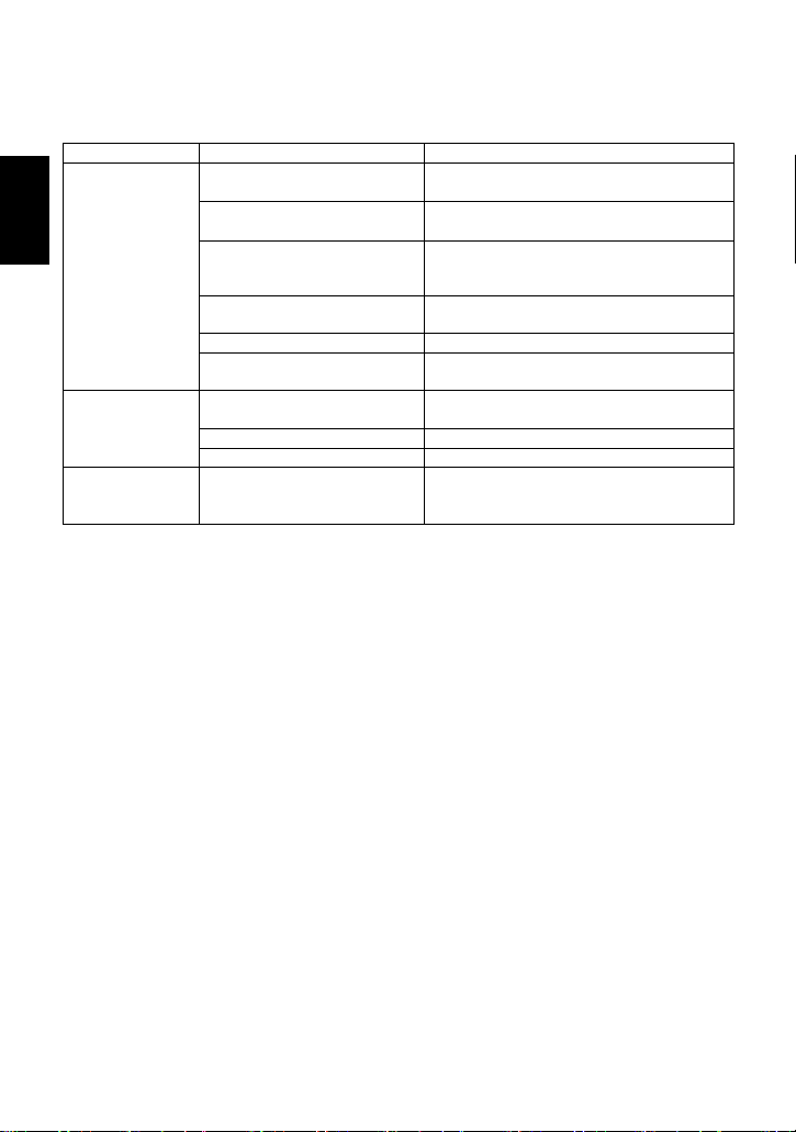
2. Specifications Technische Daten Données techniques
Die Einbauhinweise beachten und die spezifizierten Betriebsgrenzen
NICHT ÜBERSCHREITEN. Nichtbeachtung kann zu Betriebsstörungen
oder Unfällen führen. Lokale Vorschriften können zur Unterschreitung der
angegebenen Werte zwingen.
VORSICHT
Installer le produit correctement et NE PAS l’utiliser en dehors des plages
spécifiées. En cas de dépassement des limites données, des dysfonc-
tionnements ou accidents pourraient survenir. Il se peut que des règlements
locaux limitent l'utilisation du produit en-deçà des spécifications indiquées.
ATTENTION
To avoid malfunctions, product damage, accidents or serious injury,
install properly and DO NOT use this product outside the specification
range. Local regulations may restrict the use of this product to below the
conditions quoted.
CAUTION
Connector Unit (mounted only on F46)
Universalanschlussstück (nur auf F46 montiert)
Unité de raccord (apposé sur F46 uniquement)
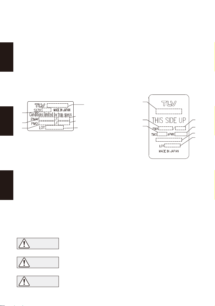
A: Model / Typ / Modèle
B: Nominal Diameter* / Größe (DN)* / Dimension (DN)*
C:
Max. Allowable Press.** / Max. zulässiger Druck** / Press. max. admissible**
D:
Max. Allowable Temp.** / Max. zulässige Temp.** / Temp. max. admissible** TMA
E: Max. Differential Press. / Max. Differenzdruck / Press. différencielle max.
F:
Max. Operating Press. / Max. Betriebsdruck / Press. max. de fonctionnement
G:
Max. Operating Temp. / Max. Betriebstemp. / Temp. max. de fonctionnement TMO
H: Valve No.***
I : Production Lot No.
/
Fertigungslos-Nr.
/
Lot de production n°
*
The nominal diameter is not printed on the trap unit nameplate when the trap unit is shipped by itself.
** Maximum allowable pressure (PMA) and maximum allowable temperature (TMA) are
PRESSURE SHELL DESIGN CONDITIONS, NOT OPERATING CONDITIONS.
*** "Valve No." is displayed for products with options. This item is omitted from the nameplate
when there are no options.
*
Größe (DN) ist bei KA-Sätzen, die ohne Universalanschlussstück versandt werden, nicht angegeben.
** Maximal zulässiger Druck (PMA) und maximal zulässige Temperatur (TMA) sind
AUSLEGUNGSDATEN, NICHT BETRIEBSDATEN.
*** Die "Valve No." wird angegeben bei Typen mit Optionen. Bei Typen ohne Optionen bleibt
diese Stelle frei.
* Si le purgeur est livré seul, le diamètre nominal (DN) n'est pas écrit sur la plaque nominative.
** Pression maximale admissible (PMA) et température maximale admissible (TMA) sont les
CONDITIONS DE CONCEPTION, PAS LES CONDITIONS DE FONCTIONNEMENT.
*** Le "Valve No." est indiqué sur les modèles avec options. Ce numéro ne figure pas sur les
modèles sans options.
Refer to the product nameplates on the trap unit AND on the connector body for detailed specifications. The
specifications displayed on each nameplate apply only to the unit on which it is mounted.
When the trap unit is installed on a connector unit and the PMA/TMA and/or PMO/TMO values displayed on
the two nameplates differ, the specifications for the assembled product are restricted to the lower values.
Das Universalanschlussstück sowie die KA-Einheit sind mit einem Typenschild versehen, welches die
technischen Daten der jeweiligen Einheit aufführt.
Stimmen die auf diesen beiden Typenschildern aufgeführten technischen Daten (PMA/TMA bzw. PMO/TMO)
nicht überein, so gelten für die zusammengesetzte Einheit die niedrigeren Werte.
Veuillez consulter la plaque nominative du purgeur ET celle du raccord pour les caractéristiques techniques
spécifiques de chaque pièce. Les valeurs inscrites sur une plaque nominative ne correspondent seulement
qu'aux caractéristique de la pièce sur laquelle la plaque est installée. Lorsqu'un purgeur et un raccord sont
joints et qu'une caractéristique technique telle que la PMO, la TMO, la PMA ou la TMA d'une pièce est
inférieure à l'autre, c'est la plus petite valeur qui correspond à la caractéristique technique de l'ensemble.
Deutsch
Français
English
5
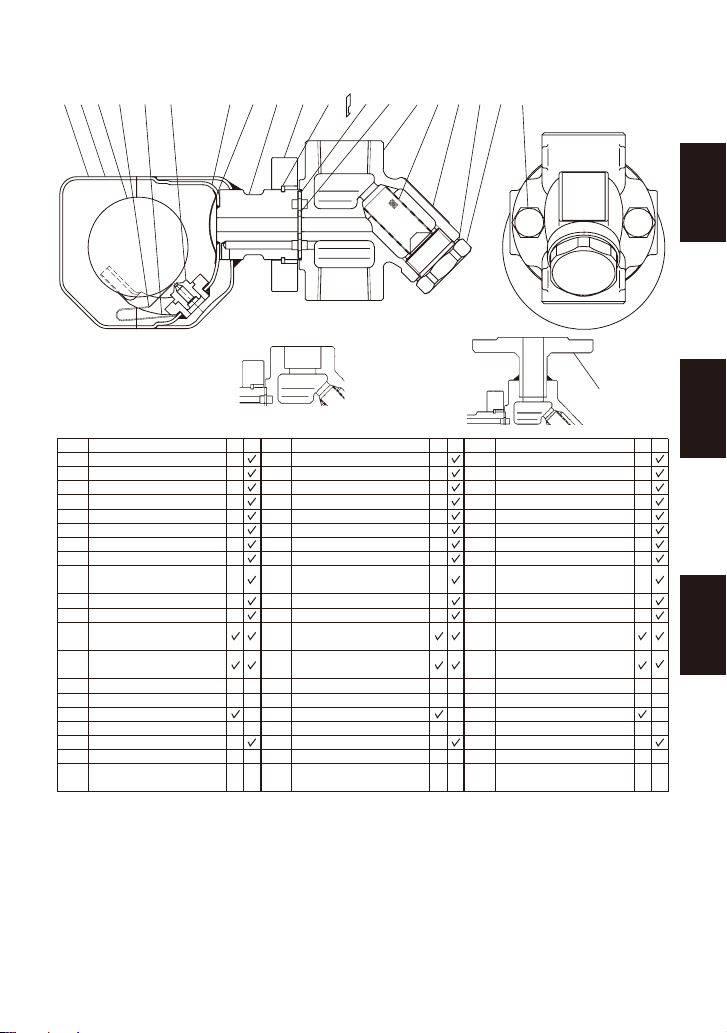
3. Configuration Aufbau Configuration
Screwed / Muffe / Taraudé
Socket Welded
Schweißmuffe
Douille à souder
Flanged
Flansch
À brides
i uq e y r wt !1 !4 !5 !6@0 !7
!9
!8
!2 !3
No.
1
2
3
4
5
6
7
8
9
10
11
12
13
14
15
16
17
18
19
20
Trap body
Inner Cover
Float
Orifice
Float Guide
Air Vent Strip
Connector Joint
Trap Screen
Nameplate
(Trap Unit)
Connector Flange
Snap Ring
Outer Connector
Gasket
Inner Connector
Gasket
Connector Body**
Screen**
Screen Holder Gasket
**
Screen Holder**
Connector Bolt
Flange
Nameplate
(Connector Unit)
Description Nr.
1
2
3
4
5
6
7
8
9
10
11
12
13
14
15
16
17
18
19
20
KA-Gehäuse
Innere Verschlusskappe
Schwimmerkugel
Ventilsitz
Schwimmerauflage
Entlüfterbügel
Verbindungsstück
KA-Schmutzsieb
Typenschild
(KA-Einheit)
Anschlussflansch
Spannring
Äußere
Flanschdichtung
Innere
Flanschdichtung
Universal-Anschlussstück**
Schmutzsieb**
Haltestopfendichtung**
Siebhaltestopfen**
Halteschraube
Flansch
Typenschild
(Universalanschlussstück)
Bauteil N°
1
2
3
4
5
6
7
8
9
10
11
12
13
14
15
16
17
18
19
20
Corps du purgeur
Couvercle interne
Flotteur
Orifice
Guide du flotteur
Bilame
Tubulure de raccord
Crépine du purgeur
Plaquette nominative
(Unité de purgeur)
Bride de raccord
Anneau élastique
Joint de raccord
externe
Joint de raccord
interne
Corps du raccord**
Crépine**
Joint de porte-crépine**
Porte-crépine**
Boulon de raccord
Bride
Plaquette nominative
(Unité de raccord)
Désignation P*
-
-
-
-
-
-
E*
-
-
-
-
-
-
-
-
-
-
-
-
-
-
-
-
-
K*
-
-
-
-
-
-
W
*
-
-
-
-
-
-
-
-
-
-
-
-
-
-
-
-
-
T*
-
-
-
-
-
-
M
*
-
-
-
-
-
-
-
-
-
-
-
-
-
-
-
-
-
o!0
* Replacement parts are available only in the following kits: M = Maintenance Kit; T = Trap Unit
** Replacement parts for F32 differ from those for F46. When ordering replacement parts, please
include the trap unit name, size, connection type and the connector unit name.
*
Ersatzteile werden nur in ganzen Einheiten geliefert: W = Wartungssatz; K = Kondensatableitersatz
** Ersatzteile für F32 entsprechen nicht denen von F46. Bei Bestellung von Ersatzteilen bitte
unbedingt Kondensatableiter-Typ, Größe, Anschlussart und Name des
Universalanschlussstück-Typs angeben.
* Pièces disponibles sous forme de jeux uniquement :
E = Jeu de pièces d'entretien ; P = Unité
du purgeur
** Les pièces de rechange de l’unité de raccord F32 diffèrent de celles de la F46. Lorsque vous
placez une commande pour des pièces de rechange, veuillez inclure le modèle du purgeur, ses
dimensions, le type de raccordement et le modèle de l’unité de raccord.
Deutsch
Français
English
6

Be sure to coat threads on the screen holder and connector bolts with anti-seize.
Die Gewinde von Siebhaltestopfen und Halteschrauben mit Schmiermittel bestreichen.
Enduire les portions filetées du porte-crépine et les boulons de raccord avec de l'anti-grippant.
* F = flanged, S = screwed, W = socket welded * F = Flansch, S = Muffe, W = Schweißmuffe.
* F = À brides, S = Taraudé, W = Douille à souder.
Screen**
Schmutzsieb**
Crépine**
Screen holder gasket**
Stopfendichtung**
Joint du porte-crépine**
Screen holder**
Siebhaltestopfen**
Porte-crépine**
Connector bolt*
Halteschraube*
Boulon de raccord*
Connector body**
Universal-Anschlussstück**
Corps du raccord**
Connector gasket*
Dichtung*
Joint*
Trap body*
KA-Gehäuse*
Corps du purgeur*
4.
Exploded View Einzelteile Pièces détachées
Tightening Torque Anzugsmoment Couples de serrage
* Trap unit S3/S5/S5H
** Connector body unit F46 or F32
* Kondensatableitersatz S3/S5/S5H
** Universal-Anschlussstück F46 oder F32
* Unité du purgeur S3/S5/S5H
** Unité de raccord F46 ou F32
Do not remove snap ring used to fix the
connector flange.
Den Spannring, welcher den Anschlussflansch
hält, nicht entfernen.
Ne retirez pas l'anneau élastique qui retient la
bride de raccord en place.
1 N
・
m 〜 〜10 kg
・
cm
No.
Nr.
N°
Description
Bauteil
Désignation
Distance across flats
Schlüsselweite
Ouverture de clé
Tightening Torque
Anzugsmoment
Couple de serrage
18 Connector Bolt
All connections and sizes
Alle Anschlüsse und Größen
Pour toutes connexions et dimensions
Halteschraube
Boulon de raccord
17
Screen Holder
Siebhaltestopfen
Porte-crépine
2
1
//
4
3
F: 15 - 25 mm
( ”, ”, 1”)*
2
14
3
/ /
S & W: 15, 20 mm ( ”, ”)*
mm
(lbf・ft)N・m
(28)
39
(44)
60
(in)
14
22
(110)
150 38
S & W: 25 mm (1
”
)*
F32
F46 100 (73)30
(
7
/
8
)
(1
1
/
2
)
(1
3
/
16
)
(
9
/
16
)
Connector Nameplate**
Typenschild
Anschlussstück**
Plaquette nominative
de l'unité de raccord**
Nameplate*
Typenschild*
Plaquette nominative*
Deutsch
Français
English
7
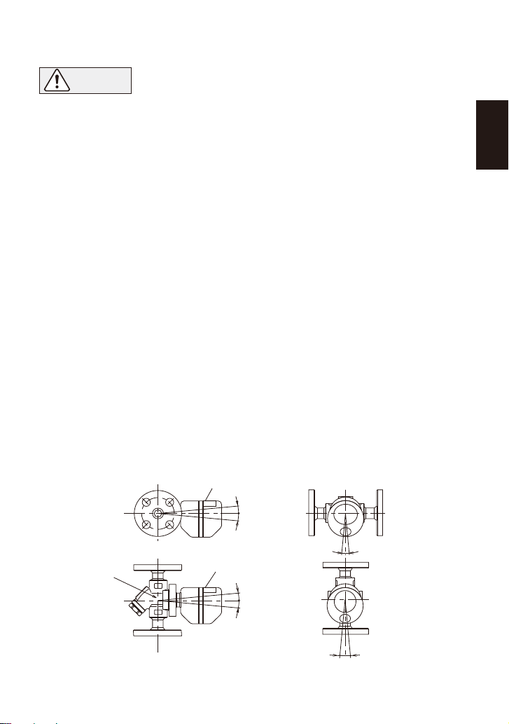
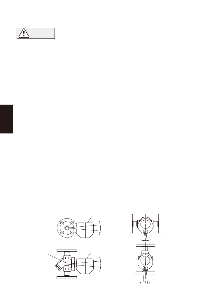
5. Proper Installation
5.1 Allowable Inclination
• Installation, inspection, maintenance, repairs, disassembly, adjustment
and valve opening/closing should be carried out only by trained
maintenance personnel.
• Take measures to prevent people from coming into direct contact with
product outlets.
• Install for use under conditions in which no freeze-up will occur.
• Install for use under conditions in which no water hammer will occur.
CAUTION
1. Before installation, be sure to remove all protective seals.
2. Before installing the steam trap, blow out the inlet piping to remove all dirt and oil.
3. In some instances, the trap unit and the connector body are sent as separate units. When
attaching them together, make sure the connector gaskets are still in place after having
removed their protective seal (see page 11 for details).
4. There are no restrictions on the installation direction beyond the following conditions:
a) The arrow on the connector body must point in the direction of condensate flow.
b) The connector body must be adjusted so that the connector flange face (for connecting
to the trap unit) is in the vertical plane.
c) The nameplate on the trap unit must face upward.
d) The trap unit must be inclined no more than 5˚ horizontally and front-to-back.
5. Install a bypass valve to discharge condensate, and inlet and outlet valves to isolate the
trap in the event of trap failure or when performing maintenance.
6. Install the trap in the lowest part of the pipeline or equipment so the condensate flows
naturally into the trap by gravity. The inlet pipe should be as short and have as few bends
as possible.
7. Install a check valve at the trap outlet whenever the condensate discharge pipe leads to a
tank or recovery line, or whenever the condensate collection pipeline is connected to more
than one trap.
8. Support the pipes within 0.8 meters (2.5 ft.) on either side of the trap.
9.
In order to avoid excessive back pressure, make sure the discharge pipes are large enough
10. The use of unions is recommended to facilitate connection and disconnection of screwed
models.
5˚ 5˚
5˚
5˚
Connector bolt
5˚
5˚
5˚ 5˚
Nameplate
Nameplate
English
8
―9―
English
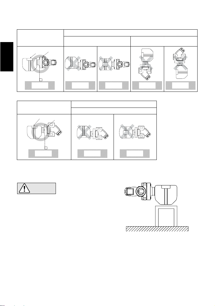
5.3 FS5/FS5H, Screwed Model
5.2 Installation Examples
When using the product on a horizontal pipe, fasten it
so that the trap cannot rotate.
To ensure the correct operation of the FS5/FS5H
Free Float Steam Trap, it is essential that the float
mechanism is operating in the horizontal plane. When
the screwed model is used in a horizontal pipe, there
is a danger that the weight of the steam trap will
cause the body to rotate on the pipe, so that the trap
mechanism will no longer be in a horizontal plane. In
order to prevent this from happening, it is important
that the trap body be supported as shown.
CAUTION
Nameplate
Nameplate
Connector
Flange
Connector
Flange
Horizontal Piping
Vertical Piping
Correct
Correct
Nameplate is not facing upwards. Universal Connector Flange is not
in the vertical plane.
Incorrect
Incorrect
Nameplate is not facing upwards.
Ground GroundGround
Ground Ground Ground
Ground Ground

English
―10―
7. Inspection and Maintenance
• Installation, inspection, maintenance, repairs, disassembly, adjustment
and valve opening/closing should be carried out only by trained
maintenance personnel.
• Before removing the trap body from the connector body, close the inlet
and outlet isolation valves and wait until the entire unit has cooled
completely. Failure to do so may result in burns.
• Be sure to use the proper components and NEVER attempt to modify the
product.
CAUTION
Operational inspections should be performed at least twice per year, or as called for by trap
operating conditions. Steam trap failure may result in temperature drop in the equipment, poor
product quality or losses due to steam leakage.
While the trap body itself is maintenance-free, there may be other causes of malfunction, as
described in the “Troubleshooting” and “Piping Arrangement” chapters. If the corrective
measures described therein do not solve the problem, it is possible that the trap has reached the
end of its service life and requires replacement.
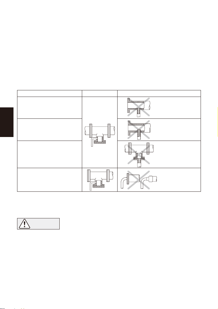
6. Piping Arrangement
1. Is the pipe diameter suitable?
2. Has the trap unit been installed within the allowable inclination and with the arrow on the
body pointing in the direction of flow?
3. Has sufficient space been secured for maintenance?
4. Have maintenance valves been installed at the inlet and outlet? If the outlet is subject
to back pressure, has a check valve been installed?
5. Is the inlet pipe as short as possible, with as few bends as possible, and installed so that the
condensate will flow naturally down into the trap?
6. Has the piping work been done correctly, as shown in the table below?
Check to make sure that the pipes connected to the trap have been installed properly.
Requirement
Install a catchpot with the
proper diameter.
Make sure the flow of
condensate is not obstructed.
To prevent rust and scale from
flowing into the trap, connect
the inlet pipe 25 - 50 mm (1 - 2 in)
above the base of the T-pipe.
When installing on the blind
end, make sure nothing
obstructs the flow of
condensate.
Correct Incorrect
Diameter is too
small.
Rust and scale
flow into the trap
with the
condensate.
Condensate
collects
in the pipe.
Diameter is too
small and inlet
protrudes into pipe.

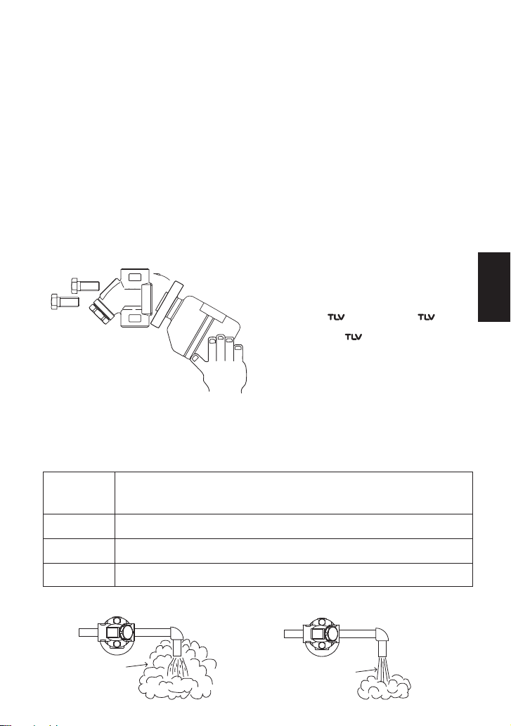
8. Operational Check
Flash Steam
White jet
containing
water droplets
Live Steam
Leakage
Clear, slightly
bluish jet
Normal: Condensate is discharged continuously with flash steam and the sound of
flow can be heard. If there is very little condensate, there is almost no
sound of flow.
Blocked: No condensate is discharged. The trap is quiet and makes no noise,
and the surface temperature of the trap is low.
Blowing: Live steam continually flows from the outlet and there is a continuous
metallic sound.
Live steam is discharged through the trap outlet together with the
condensate and there is a high-pitched sound.
A visual inspection can be carried out to aid in determining the necessity for immediate
maintenance or repair, if the trap is open to atmosphere. If the trap does not discharge to
atmosphere, use diagnostic equipment such as TLV TrapMan or Pocket TrapMan (within their
pressure and temperature measuring range).
(When conducting a visual inspection, flash steam is sometimes mistaken for steam leakage. For
this reason, the use of a steam trap diagnostic instrument such as TLV TrapMan is highly
recommended.)
Steam
Leakage:
Fig. A
7.1 Separating/Attaching Trap and Connector Bodies
1. Loosen and remove the connector bolts, remove the entire trap unit from the connector body
and take it to a repair area where it can be supported in a vise during disassembly.
2.A When reinstalling the original trap:
a. Using a small screwdriver, remove the old gaskets from their housings in the trap body,
then clean the housings.
b. New connector gaskets must be installed.
c. To facilitate assembly and prevent loosening of the gaskets, apply a small amount of
suitable adhesive at 120˚ intervals around the outer edge of the gaskets.
d. Holding the trap body so that the gasket housings are horizontal, place the gaskets into
the housings.
2.B When installing a replacement trap:
a. Be sure to remove all protective seals, making sure the connector gaskets are still in place
after having removed their seal.
b. Before installation, scrape the mounting surface of the connector body clean using a soft
tool.
3. Align the bottom edge of the trap body with that of the connector body (see Fig. A below),
making sure the gasket housings on the trap body align with the corresponding recesses in
the connector body. Maintaining the proper alignment, close the tops together until the two
faces are flush, making sure that connector gaskets remain in position.
4. Insert the connector bolts and finger-tighten, keeping trap and connector bodies flush.
Tighten the connector bolts to the proper torque (see p.7).
The S3/S5/S5H trap unit is designed for use
with F46 and F32 connector units and
V1/V2/V1P/V2P Series trap stations. It is not
compatible with F46J connector units.
The connector unit name is indicated on the
connector body.
11

Instructions for Plug / Holder Disassembly and Reassembly
The seal on the threaded plugs/holders found on TLV products is formed by a flat metal
gasket. There are various installation orientations for the gaskets, such as horizontal,
diagonal and downward, and the gasket may be pinched in the thread recesses during
assembly.
Instructions for Disassembly and Reassembly
①Remove the plug/holder using a tool of the specified
size (distance across flats).
②The gasket should not be reused. Be sure to
replace it with a new gasket.
③Clean the gasket surfaces of the plug/holder and the
product body using a rag and/or cleaning agents, then
check to make sure the surfaces are not scratched or
deformed.
④Coat both the gasket surface of the plug/holder and
the threads of the plug/holder with anti-seize, then
press the gasket onto the center of the gasket
surface of the plug/holder, making sure the
anti-seize affixes the gasket tightly to the
plug/holder. Check to make sure the gasket is not
caught in the recesses of the threads.
⑤Hold the plug/holder upside down to make sure that
the anti-seize makes the gasket stick to the
plug/holder even when the plug/holder is held
upside down.
⑥Screw the plug/holder by hand into the product body
while making sure that the gasket remains tightly
affixed to the center of the gasket surface of the
plug/holder. Make sure the entire gasket is making
contact with the gasket surface of the product body.
It is important at this point to make sure the gasket
is not pinched in the thread recesses of the
plug/holder.
⑦Tighten the plug/holder to the proper torque.
⑧Next, begin the supply of steam and check to make sure there is no leakage from the part
just tightened. If there is leakage, immediately close the inlet valve and, if there is a bypass
valve, take the necessary steps to release any residual pressure. After the surface of the
product cools to room temperature, repeat the procedure beginning from step ①.
Gasket
Do not pinch gasket
in thread recesses
Coat with anti-seize
Gasket Surface
③
④
⑤
⑥
English
12
9. Troubleshooting
If the expected performance is unachievable after installation of the steam trap, read chapters 5
and 6 again and check the following points for appropriate corrective measures.
NOTE: When replacing parts with new, use the parts list on page 6 for reference, and replace with
parts from the Maintenance Kit and/or the Trap Unit.
No condensate is
discharged
(blocked), or
discharge is poor
Pressure exceeds maximum
operating pressure
Problem Cause Corrective Measures
Replace trap with appropriately rated model
or, if possible, reduce steam pressure
Clean the pipelines
Clean screen or channels
Replace the trap body with a new one
Replace with larger trap
Perform a bypass blowdown, or close the
trap inlet valve and allow the trap to cool
Correct the installation
Reinforce trap piping supports
Examine the piping for problems
Tighten to the proper torque (see page 7)
or replace gaskets
Pipelines upstream or down-
stream of the trap are clogged
In the connector body, the
screen or the inlet and outlet
channels are clogged
In the trap body, the inlet and
outlet channels are clogged
The trap capacity is too small
Steam locking has occured
Trap is installed above the
maximum allowable inclination
Severe vibration of trap
Water hammer has occurred
Screen holder gasket or
connector gaskets are loose or
damaged
Steam leakage or
blow-off
Steam leaks from
a place other than
the outlet
―13―
English

10.2 Operation Instructions for BD2
BD2
Coat with
Anti-Seize
Torque (T) and Distance Across Flats (D)
BD2 Valve ①
Screen Holder Gasket
Discharge Hole
Valve Stopper Pin
BD2 Valve Seat
(Screen Holder)
Screen
②
BD2 Valve
BD2
Valve Seat
(Screen
Holder)
F46
F32
Screwed & Socket Welded
25 mm (1")
All connections and sizes
Screwed & Socket Welded
Flanged 15 - 25 mm ( "-1")
2
1
/
15, 20 mm ( ", ")
2
1
/
4
3
/
②
①
①
②
(T): 30 N・m (22 lbf・ft)
(D): 17 mm
( ")
32
21
/
(T): 100 N・m (73 lbf・ft)
(D): 30 mm
(1 ")
16
3
/
(T): 60 N・m (43 lbf・ft)
(D): 22 mm
( ")
8
7
/
(T) : 150 N・m (110 lbf・ft)
(D) : 38 mm (1
")
2
1
/
Note: Do not leave the vicinity while the blowdown valve is in the open position.
CAUTION • Always wear eye protection and heat-resistant gloves when operating the
blowdown valve. Failure to do so may result in burns or other injury.
• When operating the blowdown valve, stand to the side well clear of the
outlet to avoid contact with internal fluids that will be discharged. Operate the valve slowly and
surely, taking care to avoid the area from which internal fluids are discharged and any fluids
deflected off piping or the ground etc. Failure to do so may result in burns or other injury.
• Do not excessively loosen the BD2 valve when opening the blowdown valve. The valve stopper
pin installed to prevent the BD2 valve from being removed may break and internal pressure may
result in the BD2 valve being blown off, leading to injuries, damage and fluid discharge, causing
burns.
1. With two wrenches, firmly hold the BD2 Valve Seat (Screen Holder) ②(22 mm, ") in place
while slowly opening the BD2 Valve ①(17 mm, "). Be careful to avoid contact with fluid that
will be discharged through the hole in the center of the blowdown valve as the valve opens.
2. Close the BD2 Valve ①and tighten to a torque of 30 N·m (22 lbf·ft), and confirm that there is
no leakage. If leakage continues, dirt or scale may prevent the valve from sealing. Open and
blow out again, then try to close once more.
32
21
/
8
7
/
10.1 Reassembly of Blowdown Valve
10. Optional Blowdown Valve BD2
The BD2 Blowdown Valve, installed in place of the screen holder, uses internal pressure to blow
out condensate/steam, dirt and scale to the atmosphere.
CAUTION • Installation, inspection, maintenance, repairs, disassembly, adjustment
and valve opening/closing should be carried out only by trained
maintenance personnel.
•When disassembling or removing the product, wait until the internal pressure equals
atmospheric pressure and the surface of the product has cooled to room temperature.
• Do not tighten the BD2 valve or the BD2 valve seat in excess of the appropriate tightening
torque. Over-tightening may cause breakage to threaded portions, which may cause burns,
other injuries or damage.
1. Clean the trap, BD2 threads, and sealing surfaces, and
apply a small amount of anti-seize.
2. Replace gasket.
3. Carefully place the gasket over the threaded portion,
and position carefully so that it does not
become off-center.
4. Fasten to the steam trap with the proper torque.
English
14
5. Einbauhinweise
• Einbau und Ausbau, Inspektion, Wartungs- und Reparaturarbeiten,
Öffnen/Schließen von Armaturen, Einstellung von Komponenten, dürfen
nur von geschultem Wartungspersonal vorgenommen werden.
• In sicherer Enfernung von Auslassöffnungen aufhalten und andere
Personen warnen, sich fernzuhalten.
• Kondensatableiter in frostsicherer Umgebung einbauen, oder
entsprechende Frostschutzeinrichtungen vorsehen.
• Kondensatableiter nur an Stellen einbauen, an denen kein Wasserschlag
eintreten kann.
VORSICHT
1. Vor dem Einbau die Transport-Schutzkappen entfernen.
2. Vor Einbau Leitung durchblasen, um Öl und Verschmutzungen zu entfernen.
3. Manchmal werden Universal-Anschlussstück und Kondensatableiter getrennt verschickt.
Dann ist darauf zu achten, dass nach Abnahme der Schutzkappe am Kondensatableiter die
Dichtringe noch sicher an ihrem Platz sitzen (siehe Seite 18).
4. Unter Berücksichtigung der folgenden Bedingungen kann das Universal-Anschlussstück in
jeder beliebigen Lage eingbaut werden:
a) Der Pfeil auf dem Anschlussstück muss in Durchflussrichtung zeigen.
b) Das Universal-Anschlussstück muss so eingebaut werden, dass die Flanschfläche zum
Anschluss des Kondensatableiters senkrecht steht.
c) Der Kondensatableiter muss mit dem Typenschild nach oben eingebaut werden.
d) Die Schräglagentoleranzen zur Lotrechten betragen 5˚.
5. Um Wartung und Inspektion zu erleichtern, wird der Einbau von Absperrorganen vor und
hinter dem Kondensatableiter empfohlen. Auch sollte eine Umgehungsleitung zur
Notentwässerung vorgesehen werden.
6. Die Zuführleitung sollte kurz sein, so wenige Krümmer wie möglich aufweisen und ist so zu
verlegen, dass das Kondensat durch Schwerkraftwirkung dem KA zufließen kann.
7. Falls die Auslassleitung in einen Tank oder eine Kondensatrückführleitung mündet, oder falls
mehrere Kondensatableiter an eine gemeinsame Leitung angeschlossen sind, muss ein
Rückschlagventil hinter jedem Kondensatableiter eingebaut werden.
8. Die Kondensatleitung muss im Abstand von maximal 800 mm vor und hinter dem
Kondensatableiter abgestützt werden.
9. Zur Vermeidung von zu hohem Gegendruck sind die Rohrleitungen hinter dem
Kondensatableiter groß genug zu dimensionieren.
10. Bei Muffenanschluss wird empfohlen, Rohrverschraubungen vor und hinter dem
Kondensatableiter anzubringen.
5.1 Schäglagentoleranzen
5˚ 5˚
5˚ 5˚
Typenschild
5˚
5˚
Halteschraube
5˚
5˚
Typenschild
15
Deutsch

5.3 Typ FS5/FS5H, Muffe
Falls dieser Typ in eine waagerechte Leitung eingebaut
wird, muss er gegen Verdrehung gesichert werden.
Um einen sicheren Betrieb des Freischwimmer-
Kondensatableiters FS5/FS5H zu gewährleisten, muss
der Schwimmermechanismus in einer horizontalen
Ebene liegen. Wenn der Typ mit Muffenverbindung in
eine horizontale Rohrleitung eingebaut wird, besteht
die Gefahr, dass der Kondensatableiter durch sein
Gewicht aus der horizontalen Ebene herausgedreht
wird. Um dies zu verhindern muss er, wie gezeigt,
abgestützt werden.
VORSICHT
5.2 Installationsbeispiele
Typenschild
Typenschild
KA-Flansch
KA-Flansch
Horizontale Leitung
Vertikale Leitung
Richtig
Richtig
Typenschild zeigt nicht nach oben Kondensatableiter-Flanschfläche
steht nicht senkrecht
Falsch
Falsch
Typenschild zeigt nicht nach oben
Boden BodenBoden
Boden Boden Boden
Boden Boden
―16―
Deutsch
7. Inspektion und Wartung
Es wird empfohlen, mindestens zweimal pro Jahr oder, je nach Betriebsweise, in kürzeren
Zeitabständen, eine Prüfung mit einem geeigneten Instrument (z. B. TrapMan) durchzuführen.
Fehlerhafte Kondensatableiter führen zu unerwünschten Dampfverlusten.
Der Kondensatableiter ist wartungsfrei. Jedoch können an anderer Stelle Betriebsstörungen
auftreten, die im Kapitel 9, “Fehlersuche” und Kapitel 6, “Rohrleitungsführung” erläutert werden.
Falls die dort vorgeschlagenen Gegenmaßnahmen nicht zur Beheburg der Fehler führen, liegt
möglicherweise am Kondensatableiter Verschleiß vor und er muss daher, wie folgt, ausgetauscht
werden.
VORSICHT • Einbau und Ausbau, Inspektion, Wartungs- und Reparaturarbeiten,
Öffnen/Schließen von Armaturen, Einstellung von Komponenten, dürfen
nur von geschultem Wartungspersonal vorgenommen werden.
• Vor dem Öffnen des Kondensatableiters sind die Absperrarmaturen auf
beiden Seiten zu schließen. Gehäuse auf Raumtemperatur abkühlen
lassen. Nichtbeachtung kann zu Verbrennungen führen.
• Zur Reparatur nur Original-Ersatzteile verwenden und NICHT
VERSUCHEN, das Produkt zu verändern.
6. Rohrleitungsführung
1. lst die Nennweite groß genug?
2. Wurde der KA innerhalb der Schräglagentoleranz und mit dem Pfeil in Durchflussrichtung
eingebaut?
3. lst genügend Platz für Wartungsarbeiten vorhanden?
4. Wurden vor und hinter dem KA Absperrarmaturen eingebaut? Falls Gegendruck besteht:
Wurde ein Rückschlagventil vorgesehen?
5. lst die Zuleitung so kurz wie möglich, hat sie so wenig Krümmer wie möglich und kann das
Kondensat durch Schwerkraft zufließen?
6. Wurden die Rohrleitungen so ausgeführt wie unten beschrieben?
Stellen Sie sicher, dass die Rohrleitungsarbeiten richtig ausgeführt und der KA wie beschrieben
eingebaut wurde.
Vorschrift
Kondensatstutzen mit aus-
reichendem Durchmesser
einbauen
Für ungehinderten
Kondensatzufluss
sorgen
Um Rost und sonstige Ab-
lagerungen vom KA fernzuhalten
muss die Zuleitung 25 - 50 mm
über dem Deckel des Stutzens
angeschlossen werden
Bei Einbau an Leitungsenden ist
die nebenstehende Anschlussart
vorzusehen, damit das Kondensat
ungehindert abfließen kann
Richtig Falsch
Durchmesser zu
klein
Rost und sonstige
Ablagerungen
gelangen mit dem
Kondensat in den KA
Kondensat sammelt
sich in Rohrleitung
an
Durchmesser zu klein
und Abflussrohr ragt
in Rohrleitung hinein
Deutsch
17
8. Funktionsprüfung
Entspannungs-
dampf
Weißer
Strahl mit
Dampftröpfchen
Dampfverlust
Klarer, leicht
bläulicher Strahl
Blockiert: Kondensatabfluss nicht feststellbar. Der KA macht kein Geräusch und seine
Oberflächentemperatur ist niedrig.
KA bläst: Sattdampf tritt kontinuierlich an der Auslassseite aus und ein metallisch
klingendes Geräusch ist hörbar.
Dampfverlust: Sattdampf, vermischt mit Kondensat tritt mit einem pfeifenden Geräusch
an der Auslassseite aus.
Falls der Kondensatableiter das Kondensat ins Freie abführt, können visuelle Inspektionen einen
Hinweis geben, ob sofortige Wartung oder Reparatur notwendig ist. An Kondensatrückführlei-
tungen angeschlossene KA können mit geeigneten Messgeräten, z. B. TLV TrapMan oder
Pocket TrapMan (innerhalb ihrer Druck-und Temperaturmessbereiche) geprüft werden.
(Bei visueller Inspektion wird oft Entspannungsdampf mit Dampfverlust verwechselt. Daher wird
empfohlen, im Zweifel Messgeräte, z. B. TLV TrapMan zu verwenden) .
Normal: Kondensat wird kontinuierlich unter Bildung von Entspannungsdampf
abgeleitet. Ein entsprechendes Fließgeräusch ist zu hören. Bei geringer
Kondensatmenge ist dieses Geräusch ebenfalls geringer, oder kaum noch
wahrnehmbar.
Abbildung A
7.1 Trennen/Zusammenbau von Anschlussstück und KA
1.
Die beiden Schrauben am Anschlussflansch lösen, den KA abnehmen und in einer geeigneten
Werkstatt in den Schraubstock spannen.
2.A
Bei Wiederverwendung des ursprünglichen Kondensatableiters:
a. Die alten Dichtringe mit einem kleinen Schraubenzieher herausheben und ihr Gehäuse mit
einem geeigneten Werkzeug reinigen.
b. Es müssen neue Dichtringe eingesetzt werden.
c. Um ein Herausfallen der Dichtringe zu verhindern und um die Montage zu erleichtern einen
Tropfen Klebstoff an drei Stellen am äußeren Umfang der Dichtringe, im Abstand von ca.120˚
auftragen.
d. Den Kondensatableiter so halten, dass die Dichtring-Gehäuse horizontal liegen und die
Dichtringe einsetzen.
2.B
Bei Verwendung eines Austausch-KA:
a. Alle Transport-Schutzkappen entfernen und sich vergewissern, dass die Dichtringe noch
sicher an ihrem Platz sitzen.
b. Mit einem geeigneten Werkzeug die Dichtflächen am Universal-Anschlussstück reinigen.
3. Den unteren Rand des KA an das untere Ende des Universal-Anschlussstücks halten (siehe Abb.
A
unten) und die beiden Bauteile aufeinander zuführen. Beachten, dass die Dichtringe sich nicht
lösen und herausfallen und die Dichtring-Gehäuse sicher in die Ausdrehung des Anschlussstücks
eingleiten.
4. Die Halteschrauben zuerst mit der Hand und danach mit einem Momentenschlüssel auf das auf
Seite 7 angegebene Anzugsmoment anziehen.
Kondensatableitersatz S3/S5/S5H ist passend zum
Anschlussstück F46 und F32 und
Verteilerstation V1/V2/V1P/V2P. Er passt nicht auf
das Anschlussstück F46J.
Die Typenbezeichnung findet sich auf dem
Anschlussstück-Gehäuse.
Deutsch
18

Aus- und Einbau-Anleitung für Entwässerungsstopfen
Die Gewindedichtung der Entwässerungsstopfen an TLV-Kondensatableitern besteht aus
einem flachen Metallring. Stopfen und Dichtung können in verschiedenen Lagen eingebaut
werden - horizontal, diagonal oder nach unten zeigend. Wird der Metallring dabei im
Gewinde gequetscht, verliert er seine Funktionstüchtigkeit.
Ausbau und Einbau
①Den Entwässerungsstopfen mit einem
Ringschlüssel gemäß der angegeben
Schlüsselweite ausschrauben.
②Einmal eingebaute Dichtungen nicht
wiederverwenden, sondern unbedingt ersetzen.
③Die Dichtflächen am Entwässerungsstopfen und am
Kondensatableiter mit einem Lappen o.ä. säubern
und auf einwandfreien Zustand prüfen (Kratzer).
④Sowohl die Dichtfläche, als auch das Gewinde
des Entwässerungsstopfens mit Schmiermittel
bestreichen. Dann den Dichtring zentriert auf die
Dichtfläche des Stopfens bringen, sodass der
Ring aufgrund des Schmiermittels am Stopfen
haftet. Der Dichtring darf nicht in eine
Gewindevertiefung verrutschen.
⑤Den Entwässerungsstopfen zur Probe der
Haftung des Dichtringes nach unten richten.
⑥Den Entwässerungsstopfen per Hand in den
Kondensatableiter eindrehen und dabei darauf
achten, dass der Dichtring zentriert auf der
Dichtfläche des Stopfens bleibt. Darauf achten,
dass der Dichtring nicht in das Gewinde
verrutscht, besonders wenn der Dichtring Kontakt
auch mit der Dichtfläche des Kondensatableiters
bekommt.
⑦Den Entwässerungsstopfen mit dem
ausgewiesenen Drehmoment festziehen.
⑧Führen Sie als nächstes eine Dichtigkeitsprüfung unter Dampf vor und achten besonders
auf das soeben eingebaute Bauteil. Falls Leckage auftritt sofort die Absperrarmatur an der
Einlassseite schließen und den Restdruck ablassen, falls eine Umgehungsleitung installiert
ist. Nach dem Ausgleich mit dem Umgebungsdruck und dem Abkühlen der
Produktoberflächen auf Raumtemperatur Aus- und Einbau ab ①wiederholen.
Dichtfläche
Dichtung
Dichtung nicht in das
Gewinde bringen
Mit Schmiermittel
versehen
③
④
⑤
⑥
―19―
Deutsch
This manual suits for next models
6
Table of contents
Languages:
Other TLV Industrial Equipment manuals


Popular Industrial Equipment manuals by other brands


CAVIDYNE
CAVIDYNE CaviBlaster 1030-ROV Operation & maintenance manual

Siemens
Siemens HMS-S installation instructions

Wilfley
Wilfley SolidLock Supplemental Assembly Manual

ARTHUR HOLM
ARTHUR HOLM AHD2TL user manual

SCHUNK
SCHUNK AGE-F-XY Assembly and operating manual

Numa
Numa Champion 330 Care & maintenance instructions