TLV SR-3 User manual

172-65207A-08 (SR-3/SR-8) 8 October 2020
Manufacturer
881 Nagasuna, Noguchi, Kakogawa, Hyogo, 675-8511, Japan
Tel: [81]-(0)79-422-1122 Fax: [81]-(0)79-422-0112
Copyright © 2020 by TLV CO., LTD. All rights reserved
Steam Condensing
Heat Exchanger
SR-3 / SR-8

172-65207A-08 (SR-3/SR-8) 8 Oct 2020
1
Contents
Introduction ..............................................................................1
Safety Considerations..............................................................2
Product Description..................................................................4
Intended Use ........................................................................4
System Principle...................................................................5
Specifications...........................................................................6
Configuration............................................................................7
Installation................................................................................8
Precautions before Installation .............................................8
Installation example for piping to/from the SR unit .............10
Piping Installation 1: Waste Steam Inlet Piping..................11
Piping Installation 2: Condensate Outlet Piping, Blowdown
Piping and Overflow Piping for Exhaust Pipe........................12
Piping Installation 3: Exhaust Piping...................................13
Piping Installation 4: Water Inlet and Outlet Piping.............16
Operation ...............................................................................17
Inspection and Maintenance..................................................19
Troubleshooting .....................................................................20
EXPRESS LIMITED WARRANTY................................21
Introduction
Thank you for purchasing the TLV SR steam condensing heat exchanger.
This product has been thoroughly inspected before being shipped from the
factory. When the product is delivered, before doing anything else, check the
specifications and external appearance to make sure nothing is out of the
ordinary. Also be sure to read this manual carefully before use and follow the
instructions to be sure of using the product properly.
If detailed instructions for special order specifications or options not contained
in this manual are required, please contact TLV for full details.
This instruction manual is intended for use with the model(s) listed on the
front cover. It is necessary not only for installation but for subsequent
maintenance and troubleshooting. Please keep it in a safe place for future
reference.

172-65207MA-08 (SR-3/SR-8) 8 Oct 2020
2
Safety Considerations
Read this section carefully before use and be sure to follow the instructions.
Installation, inspection, maintenance, repairs, disassembly, adjustment and valve
opening/closing should be carried out only by trained maintenance personnel.
The precautions listed in this manual are designed to ensure safety and prevent
equipment damage and personal injury. For situations that may occur as a result
of erroneous handling, three different types of cautionary items are used to
indicate the degree of urgency and the scale of potential damage and danger:
DANGER, WARNING and CAUTION.
The three types of cautionary items above are very important for safety: be sure to
observe all of them as they relate to installation, use, maintenance, and repair.
Furthermore, TLV accepts no responsibility for any accidents or damage occurring
as a result of failure to observe these precautions.
Symbols
Indicates a DANGER, WARNING or CAUTION item.
DANGER
Indicates an urgent situation which poses a threat of death or
serious injury
WARNING
Indicates that there is a potential threat of death or serious injury
CAUTION
Indicates that there is a possibility of injury or equipment /
product damage
CAUTION
Install properly and DO NOT use this product outside the
recommended operating pressure, temperature and other
specification ranges.
Improper use may result in such hazards as damage to the product
or malfunctions that may lead to serious accidents. Local
regulations may restrict the use of this product to below the
conditions quoted.
Use hoisting equipment for heavy objects (weighing
approximately 20 kg (44 lb) or more).
Failure to do so may result in back strain or other injury if the object
should fall.
Take measures to prevent people from coming into direct
contact with product outlets.
Failure to do so may result in burns or other injury from the
discharge of fluids.
When disassembling or removing accessories used with the
product, wait until the internal pressure equals atmospheric
pressure and the surface of the product has cooled to room
temperature.
Disassembling or removing accessories from the product when it is
hot or under pressure may lead to discharge of fluids, causing
burns, other injuries or damage.
Continued on the next page

172-65207MA-08 (SR-3/SR-8) 8 Oct 2020
3
CAUTION
Be sure to use only the recommended components when
repairing the product, and NEVER attempt to modify the
product in any way.
Failure to observe these precautions may result in damage to the
product and burns or other injury due to malfunction or the
discharge of fluids.
Do not use excessive force when connecting threaded pipes to
the product.
Over-tightening may cause breakage leading to fluid discharge,
which may cause burns or other injury.
In case of unexpected steam flow, connect piping from the
exhaust outlet to a safe area.
Unexpectedly high steam volumes may cause high-temperature
condensate to be discharged through the exhaust outlet, which may
in turn cause burns or other injury.
Operate valves slowly and carefully.
Opening or closing valves too quickly may cause water hammer to
occur, the impact of which could cause damage to equipment.
Use only under conditions in which no freeze-up will occur.
Freezing may damage the product, leading to fluid discharge, which
may cause burns or other injury. If the water seal or inside of the
tube freeze, the inside of the product may be pressurized which
could cause problems on equipment or devices that are connected
to the product.

172-65207MA-08 (SR-3/SR-8) 8 Oct 2020
4
Product Description
Intended Use
The SR-3/SR-8 is an atmospheric indirect heat exchanger for recovering heat energy
from waste or flash steam for applications where the steam cannot otherwise be utilized.
By using this product for waste heat recovery or steam condensation, system energy
efficiency, work environment, and plant scenery can be improved without increasing
back pressure on steam-using equipment.
Usages
Flash steam from applications such as steamers, sterilizers and vulcanizers
where the steam cannot otherwise be utilized and released to the atmosphere
Flash steam escaping from
hot water/processing tanks
Flash steam escaping from
condensate tanks into the
atmosphere
NOTE: Limited to applications
in which steam
incorporates no air or
non-condensable gases.
Improvement effect
Lower system steam usage
by collecting unusable
100 C (212 F) steam and
employing it in processes
such as water heating which
previously used main line
steam
Improves work environment
and plant scenery by
eliminating clouds of steam
generated around the plant
Because waste steam
processing can be carried
out indoors, it is not
necessary to construct
outdoor duct piping; further
reducing costs
Steam Trap Condensate
Recovery
Condensate
Recovery Tank
Bad effect on products from
flash steam
Bad image
to local
residents
Bad effect on
building/
equipment
from humidity
Eliminate
flash steam
Condensate
Recovery
Condensate
Condensate
Recovery Tank
Recovery Tank
Steam Trap
Energy-saving
effect Use of
hot water

172-65207MA-08 (SR-3/SR-8) 8 Oct 2020
5
System Principle
Because the SR-3/SR-8 steam condensing heat exchanger does not have any valve
parts on the Waste Steam Recovery side, it does not create any back-pressure on
upstream equipment.
For this reason, it can be directly connected to and used with feed water tanks and
other vessels that do not meet pressure vessel regulations in most locations. Consult
TLV for details.
Concerning the construction of the unit, there is a condensate outlet in the base of
the heat exchanger. This allows a water seal to be maintained which directly
prevents steam leakage. Thus, with a similar construction to closed type heat
exchangers, it can ensure an equivalent level of high efficiency heat exchange.
Operation flow of Steam Condensing Heat Exchanger SR-3/SR-8 (hereafter, SR)
①Waste steam flows into the SR from
equipment connected to the steam inlet.
②Waste steam which has flowed into the
SR (shell side) transfers heat to cold
water inside the heat transfer coil.
③Upon transferring heat the waste
steam condenses and drips down to
collect in the base of the SR.
Furthermore, since condensing steam
inside an airtight space produces a fall
in pressure, the inside of the SR is
maintained at atmospheric pressure or
a very slight vacuum (-0.5 kPaG
(-7 psi)) which ensures a smooth influx
of waste steam.
④Condensate accumulated in the base
of the tank seals the outlet, and it
becomes similar in structure to a
pseudo closed type heat exchanger
⑤Furthermore, after waste steam
transfers heat away and becomes
condensate, it overflows and is
discharged to the outside
⑥If the cold water flow rate decreases, or else the ability of the cold water to
absorb heat is surpassed causing an influx of waste steam; even if waste steam
accumulates inside the SR and the pressure begins to rise; the instant that the
pressure rises above 0.5 kPaG (7 psi) (a water seal with 50 mm (2 in) of head
pressure) the water seal will be broken and waste steam will be discharged to
the atmosphere through the exhaust outlet.
(pressure will not accumulate inside the unit)
Exhaust
Outlet
Hot Water
Outlet
Heat Transfer Coil
(Stainless)
Cold Water
Inlet
Condensate Outlet
Waste
Steam
Inlet

172-65207MA-08 (SR-3/SR-8) 8 Oct 2020
6
Specifications
Install properly and DO NOT use this product outside the recommended
operating pressure, temperature and other specification ranges.
Improper use may result in such hazards as damage to the product or
malfunctions which may lead to serious accidents. Local regulations
may restrict the use of this product to below the conditions quoted.
CAUTION
Use only under conditions in which no freeze-up will occur. Freezing may
damage the product, leading to fluid discharge, which may cause burns
or other injury. If the water seal or inside of the tube freeze, the inside of the
product may be pressurized which could cause problems on equipment
or devices that are connected to the product.
CAUTION
Refer to the product nameplate for detailed specifications.
Do not install valves or orifices at the exhaust outlet, since the SR is an atmospheric
type heat exchanger.
Maximum Operating
Pressure
Maximum Operating
Temperature
Heat Transfer Surface
Area
Maximum Steam
Flow Rate
Serial No.
Model

172-65207MA-08 (SR-3/SR-8) 8 Oct 2020
7
Configuration
SR-3/SR-8
Appearance
Internal Construction
The figure above shows the SR-3.
The internal configuration of the SR-8
differs slightly from the SR-3.
* Depending on the specifications, the product may or may not feature an overflow outlet for
the exhaust pipe.

172-65207MA-08 (SR-3/SR-8) 8 Oct 2020
8
Installation
Install properly and DO NOT use this product outside the recommended
operating pressure, temperature and other specification ranges.
Improper use may result in such hazards as damage to the product or
malfunctions which may lead to serious accidents. Local regulations
may restrict the use of this product to below the conditions quoted.
CAUTION
In case of unexpected steam flow, connect piping from the exhaust
outlet to a safe area. Unexpectedly high steam volumes may cause
high-temperature condensate to be discharged through he exhaust
outlet, which may in turn cause burns or other injury.
CAUTION
Use hoisting equipment for heavy objects (weighing approximately
20 kg (44 lb) or more). Failure to do so may result in back strain or other
injury if the object should fall.
CAUTION
Do not use excessive force when connecting threaded pipes to the
product. Over-tightening may cause breakage leading to fluid
discharge, which may cause burns or other injury.
CAUTION
Precautions before Installation
Installation, inspection, maintenance, repairs, disassembly, adjustment and valve
opening/closing should be carried out only by trained maintenance personnel.
For the specific installation location of the SR, carefully consult the user.
Confirm the following items for the installation.
1. Before installing the SR, carefully discuss and ensure the installation and piping
method.
2. Do not install the SR near a stairway or emergency exit.
3. The surface for installation of the SR should be sturdy and horizontal.
As the SR is heavy equipment, anchor the legs securely on a strong and
horizontal foundation using the anchor bolts. (Dimension of anchor bolts: M16)
(Refer to the illustration on the next page regarding the position for anchor bolts
and number of anchor bolts required.)
4. For cases where people or products may come in contact with the SR unit, any
safety measures, such as insulation or isolation, should be implemented to
prevent injury.
Even if such contact is unlikely, it is recommended that the SR unit be as well
insulted as possible to increase heat efficiency.
5. Maintenance space should be secured.
Although the SR cannot be disassembled, maintenance space should be
secured for valves, etc.
(Refer to the illustration on the next page regarding maintenance space.)
6. If the SR is installed at height, make sure to install the SR such that there is
enough space to carry out maintenance work etc. with anti-drop measures such
as handrails having been implemented. We may not be able to perform technical
support service in a location where work cannot be safely carried out.

172-65207MA-08 (SR-3/SR-8) 8 Oct 2020
9
Position for anchor bolts
Maintenance Space (mm)
SR-3
120
120
PCD420
3 o19 bolt hole
/
3 o19 bolt hole
/
Anchor bolts:
M16
Total length: 80 mm (31/8in)
3 pcs.
Approx. 800 mm (2.6 ft)
Approx. 2000 mm (6.6 ft)
SR-8
3 o19 bolt hole
/
3 o19 bolt hole
/
120
120
PCD520
Anchor bolts:
M16
Total length: 220 mm (85/8in)
3 pcs.
Approx. 750 mm (2.5 ft)
Approx. 2000 mm (6.6 ft)
Anchor bolts are selected with standard seismic intensity: 1, and horizontal seismic
coefficient: 1.

172-65207MA-08 (SR-3/SR-8) 8 Oct 2020
10
Installation example for piping to/from the SR unit
Please carefully refer to the "Piping Installation" section described on the following
pages for important points regarding piping arrangements.
* Depending on the specifications, the product may or may not feature an overflow outlet for
the exhaust pipe.

172-65207MA-08 (SR-3/SR-8) 8 Oct 2020
11
Piping Installation 1: Waste Steam Inlet Piping
no condensate
accumulation points (places where piping rises or falls)
feed water tank or other“non
pressure vessel”,do not install
valves, check valves, etc. on the
steam piping.
Other cautions
The piping diameter should be sized so that the flow velocity of steam is
approximately 20 m/sec (66 ft/sec).
To handle steam without applying back pressure on steam-using equipment, it is
recommended that the piping be of the same diameter as the SR steam inlet (SR-3:
80 mm (3 in), SR-8: 150 mm (6 in)). Suggested diameters for the steam inlet piping
are as follows:
Steam Flow
kg/h (lb/h)
50
(110)
100
(220)
150
(330)
200
(440)
300
(660)
400
(880)
500
(1100)
600
(1320)
800
(1760)
Pipe Diameter
mm (in)
40
(11/2)
50
(2)
50
(2)
80
(3)
80
(3)
100
(4)
100
(4)
125
(5)
150
(6)

172-65207MA-08 (SR-3/SR-8) 8 Oct 2020
12
Piping Installation 2: Condensate Outlet Piping, Blowdown Piping and
Overflow Piping for Exhaust Pipe
without
any rise
without any rise
Install piping from the
condensate outlet to a
safe area such as a pit
where people will not
come into contact
blow-
down piping is connected to the
condensate outlet piping
forgetting to
close the valve, delays in discover-
ing failures, the accumulated scale
in the SR flowing into the conden-
sate outlet piping
Other cautions
When back pressure is applied to the SR, it also affects the upstream equipment
from which waste steam is recovered.
Even though piping with the same diameter as the condensate outlet piping of the
SR is recommended to prevent back pressure from being applied to the SR, it is
possible to use a smaller pipe diameter depending on the length of the pipe to the
pit or discharge destination.
Suggested diameters for the condensate outlet piping are as follows:
When the condensate outlet valve or the overflow piping for exhaust pipe is
installed, make sure to use either a full-bore ball valve or a gate valve so that back
pressure does not interfere with the operation of the SR.
Pipe Length to Pit or
Recovery Destination
Less than
10 m (33 ft)
10 m to 50 m
(33 ft to 164 ft)
Greater than
50 m (164 ft)
Outlet Pipe Diameter
25 mm (1 in)
40 mm (11/2 in)
50 mm (2 in)
* Depending on the specifications, the product may or may not feature an overflow outlet for
the exhaust pipe. Products without an overflow outlet should be fitted with an overflow line of
nominal diameter 10 mm (3/8 in) or more.

172-65207MA-08 (SR-3/SR-8) 8 Oct 2020
13
Piping Installation 3: Exhaust Piping
Other cautions
Be certain to connect exhaust piping to protect against instances of unexpectedly
high-volume waste steam flow into the SR, which may cause waste steam/hot water
to be discharged.
When back pressure is applied to the SR, it also affects the upstream equipment
from which waste steam is recovered.
To prevent putting back-pressure on upstream equipment, make exhaust piping as
large in diameter, short, and with as few bends as possible.
Even though piping with the same diameter as the exhaust piping of the SR is
recommended to prevent putting back pressure on the SR, it is possible to use a
smaller pipe diameter depending on the length of the pipe to the pit or recovery
destination.
Suggested diameters for the exhaust piping are as follows:
Model
Length & Diameter of Exhaust Piping
Less than
10 m (33 ft)
10 m to 20 m
(33 ft to 66 ft)
20 m to 30 m
(66 ft to 98 ft)
Greater than
30 m (98 ft)
SR-3
50 mm (2 in)
80 mm (3 in)
100 mm (4 in)
150 mm (6 in)
SR-8
80 mm (3 in)
100 mm (4 in)
150 mm (6 in)

172-65207MA-08 (SR-3/SR-8) 8 Oct 2020
14
Connecting the duct piping to the exhaust outlet
The standard connection specification of the exhaust outlet for the SR is “duct piping
installable”.
Nipple fittings should be used to connect the SR and the piping, making sure that
there is no leakage.
Piping example
1) All duct piping should withstand high temperatures of 100 C (212 F).
Coat the nipple with duct sealant.
2) Insert the nipple into the SR, then the duct piping into the nipple.
After everything is set in place, fix with screws (screw holes on the SR: M5 2
places).
3) After fixing with screws, wrap with two or three layers of tape that can withstand
the required heat.
1)
2)
3)
About exhaust outlet / options
The exhaust outlet of the SR can be produced with a flange connection as an option.
However, specification changes after delivery cannot be accepted.
The exhaust piping should be supported firmly, making sure to avoid excessive
force on the SR.(Excessive force may lead to damage to the SR.)
In cases where the piping is welded directly to the exhaust outlet
C3 chamfering has been performed on the exhaust outlet. When welding is
performed on the exhaust outlet, the connecting tube should be also chamfered and
butt welded. Furthermore, when SUS304 is used for the SR, the piping thickness of
the exhaust outlet will be “Sch40”.

172-65207MA-08 (SR-3/SR-8) 8 Oct 2020
15
Screw holes on the exhaust port
Two M5-sized screw holes are
opened on either side of the exhaust
port, intended for use with the
standard duct connection.

172-65207MA-08 (SR-3/SR-8) 8 Oct 2020
16
Piping Installation 4: Water Inlet and Outlet Piping
Other cautions
Connect the cold water piping to the cold water inlet, and connect return piping from
the hot water outlet to an area where the hot water can be utilized. To secure an
adequate amount of cold feed water, make sure that the hydraulic pressure
differential (pressure differential between inlet and outlet) is at least equal to the
values in the following table. However, the water pressure must not exceed the
maximum operating water pressure of 1.0 MPaG (150 psig).
Required Cold
Water (t/h)
1
2
3
4
5
6
8
10
12
14
Hydraulic
Pressure
Differential
(MPa)
SR-3
0.03
0.11
0.23
0.40
0.62
—
—
—
—
—
SR-8
—
—
0.03
0.05
0.07
0.10
0.17
0.27
0.38
0.60
(1 MPa = 10.197 kg/cm2)
Required Cold
Water (lb/h)
2000
4000
6000
8000
10000
12000
16000
20000
24000
28000
Hydraulic
Pressure
Differential
(psi)
SR-3
3.6
12.9
27.8
48.2
74.0
—
—
—
—
—
SR-8
—
—
3.4
5.8
8.7
12.3
21.2
32.4
45.9
61.8
The diameter of the pipe before and after the SR varies with the required amount of
cold water, and it should be sized so that the velocity of cold water is 2 to 3 m/sec (6.6
to 9.8 ft/sec). Suggested diameters for the cold water inlet and hot water outlet piping
are as follows:
Water Flow (t/h)
1
2
3
4
5
6
7
8
10
Pipe Diameter (mm)
15
15
20
25
25
32
32
32
40
Water Flow (lb/h)
2000
4000
6000
8000
10000
12000
14000
16000
20000
Pipe Diameter (in)
1/2
1/2
3/4
1
1
11/4
11/4
11/4
11/2

172-65207MA-08 (SR-3/SR-8) 8 Oct 2020
17
Operation
Install properly and DO NOT use this product outside the recommended
operating pressure, temperature and other specification ranges.
Improper use may result in such hazards as damage to the product or
malfunctions which may lead to serious accidents. Local regulations
may restrict the use of this product to below the conditions quoted.
CAUTION
Take measures to prevent people from coming into direct contact with
product outlets. Failure to do so may result in burns or other injury from the
discharge of fluids.
CAUTION
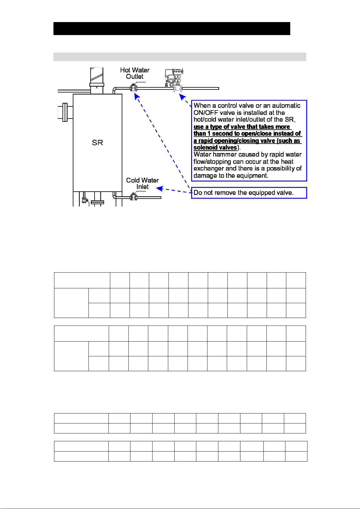
Operate valve slowly and carefully. Opening or closing valves too quickly
may cause water hammer to occur, the impact of which could cause
damage to equipment.
CAUTION
To be performed after installation and before initial operation
Make sure to flush the piping to remove welding slag, metal powder and filings.
Make sure that flange bolts etc. are securely tightened before passing steam/
water through the SR.
When conducting the test operation, start with a low steam and water flow rate
and gradually increase the load to normal operating conditions.
If you start with a normal operating load at the outset and there is a leak
somewhere in the piping, there is a risk of steam or water blowing out.
Startup
Make sure that the cold water inlet valve (A) and hot water outlet valve (B) are open
before supplying waste steam to the SR. If waste steam is supplied while the cold
water inlet valve (A) and hot water outlet valve (B) are closed, the pressure inside the
coil will increase due to volume expansion, which could damage the cold water inlet
valve (A) and hot water outlet valve (B).
1. Make sure that the blow valve (C) in the base
of the SR is closed.
2. Open the cold water inlet valve (A) and the
hot water outlet valve (B), allowing water to
pass through the SR. In cases where either
TIC (temperature control of heated water) or
FIC (flowcontrol of heated water) is used,
start up the controls.
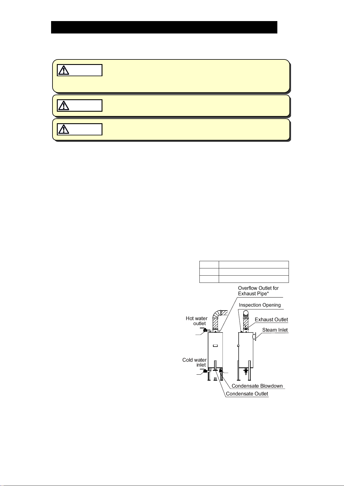
3. Open the condensate outlet valve, if any.
4. Open the steam inlet valve, if any.
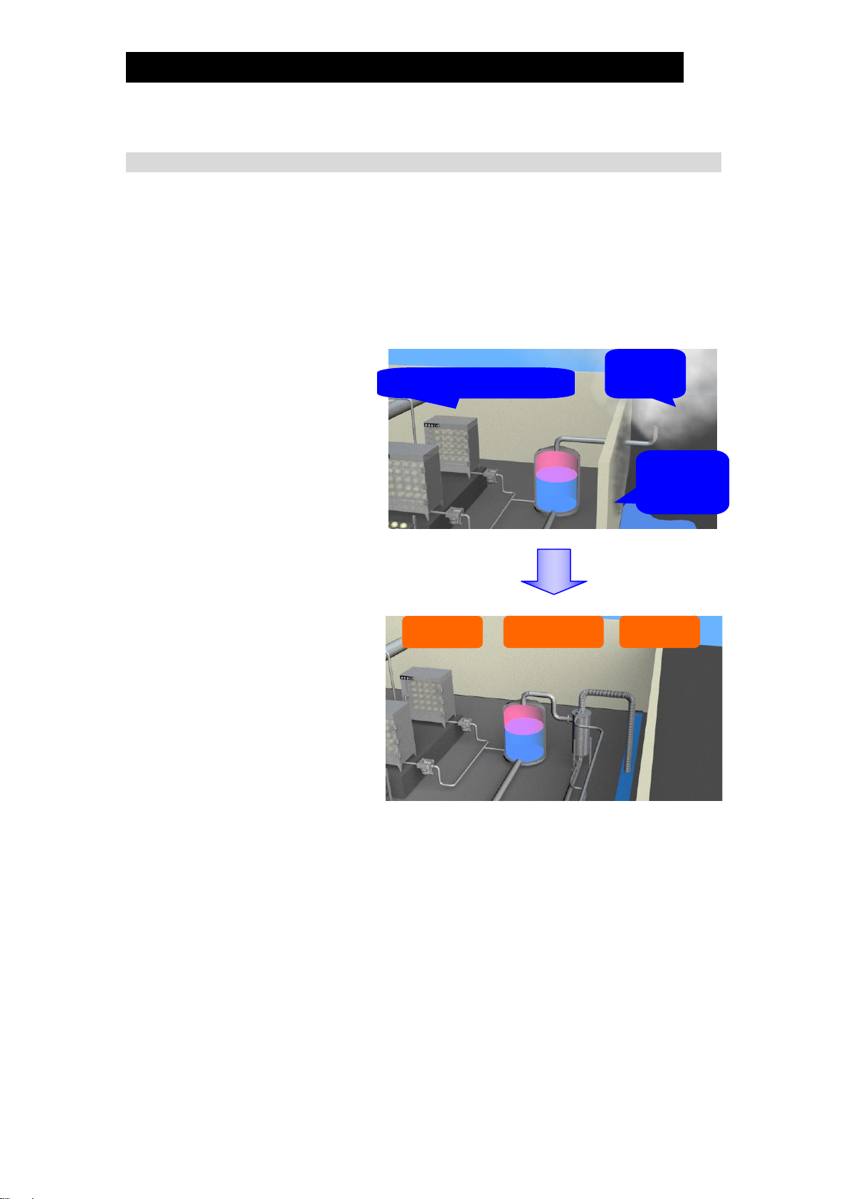
5. Startup the equipment to allow waste
steam to enter the SR.
Make sure that there are no abnormal
discharges from the exhaust outlet or
overflow outlet for exhaust pipe*, such as
blowing steam or condensate. If there is
condensate blowing, or an abnormal
sound or vibration, halt operation immediately.
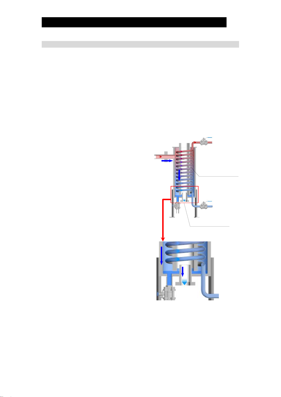
The first time you operate the SR, or when operating with the condensate blow valve
(C) open, waste steam may be discharged to the atmosphere through the exhaust
outlet or overflow outlet for exhaust pipe* immediately after initiating operation, due to
the lack of pooled condensate in the base to create an airtight water seal over the
condensate outlet. (if steam blow stops shortly then everything is normal)
A
Cold water inlet valve
B
Hot water outlet valve
C
Condensate blow valve
B
AC

172-65207MA-08 (SR-3/SR-8) 8 Oct 2020
18
* Depending on the specifications, the product may or may not feature an overflow outlet for
the exhaust pipe.
Shutdown
1. Stop the equipment, making sure that there is no flow of waste steam.
2. Close the cold water inlet valve (A) and the hot water outlet valve (B) to stop the
inflow of cold water. At this point, make sure to close the valve slowly not rapidly.
(If the valve is closed rapidly, water hammer will occur, resulting in impacts to the
SR and the surrounding piping.)
3. When the SR is to be shutdown for long periods of time, discharge all condensate
by opening the blow valve (C) at the bottom of the body.

172-65207MA-08 (SR-3/SR-8) 8 Oct 2020
19
Inspection and Maintenance
Take measures to prevent people from coming into direct contact with
product outlets. Failure to do so may result in burns or other injury from
the discharge of fluids.
CAUTION
Be sure to use only the recommended components when repairing the
product, and NEVER attempt to modify the product in any way. Failure to
observe these precautions may result in damage to the product or burns
or other injury due to malfunction or the discharge of fluids.
CAUTION
As the SR is an atmospheric type heat exchanger, there is no particular need to
perform the kind of maintenance inspections required for pressure vessels.
However, if the heat exchanging performance declines, verify that the cold water and
steam flow quantity are in compliance with the rated capacities. If they are not in
compliance, correct the flow quantities. If there are no irregularities with the flow
quantities, perform the following inspection:
Annual inspection and cleaning is recommended to prolong the product’s service life.
Inspection at cold/hot water side
1. Perform a reverse-flow chemical cleaning by pouring cleaning solution in through
the hot water outlet valve on the SR, then discharging the solution through the
cold water inlet valve.
Inspection at steam side
1. Remove the plug from the inspection opening and check the condition inside the tank.
2. If the inspection reveals heavy grime, close the condensate outlet and the
condensate blowdown outlet and perform chemical cleaning by pouring cleaning
solution through the exhaust outlet of the SR.
Other manuals for SR-3
1
This manual suits for next models
1
Table of contents
Other TLV Industrial Equipment manuals
Popular Industrial Equipment manuals by other brands

ABB
ABB ACS580-01 +C135 Series Original instructions

Micronix
Micronix PPS-28 series Reference manual

Streckfuss
Streckfuss A075/Ri operating instructions

MILLART MACHINE TOOLS
MILLART MACHINE TOOLS TB-12 Operation manual

Once
Once BioShift Single Door UV-C Germicidal Chamber instruction manual

ABB
ABB A135-M56 Operation manual