Warning
Before making any electrical wire connection or/and setting the control board, make
sure that the power switch is OFF.
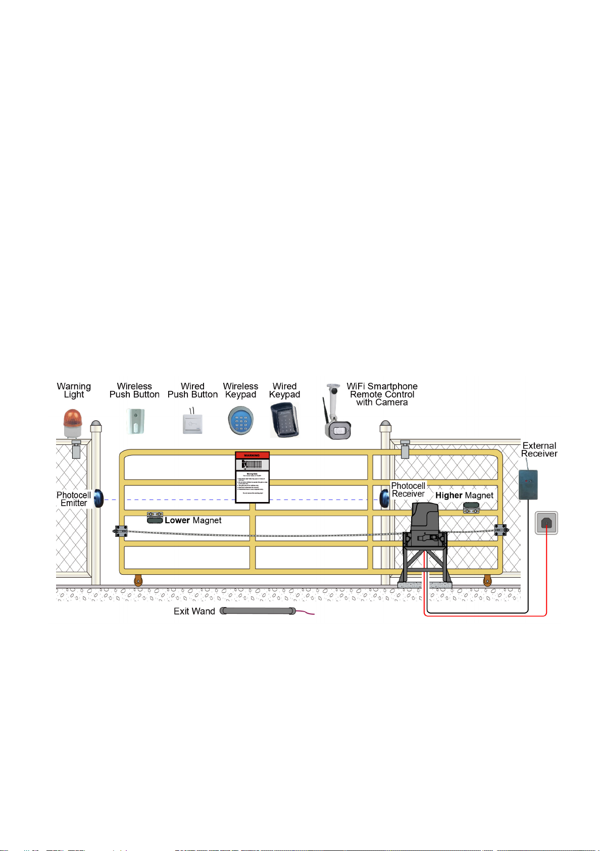
Warning: A photocell is included in the package. The photocell must be installed with the gate
opener for safety protection or the gate opener could not close properly.
1. Contactors
The A1 terminal of both contactors should be wired to the “6” terminal of the control board.
The A2 terminal of contactor1 should be connected into the “8” terminal the control board.
The A2 terminal of contactor2 should be connected into the “7” terminal the control board.
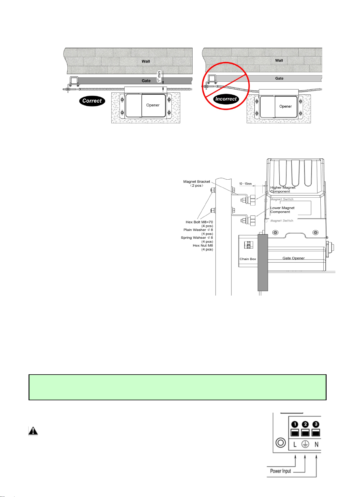
2. Limit Switches
The RED wire of the limit switches should be connected into the “9” terminal.
The BLACK wire of the limit switches should be connected into the “10” terminal.
The YELLOW wire of the limit switches should be connected into the “11” terminal.
3. Warning Light (Included in some models, refers to the actual package)
One wire of the warning light should be connected into the “4” terminal, another should be connected into
the “5” terminal.
4. Photocell Beam System (PBS) (Normally Closed)
Use a 2-core cable to connect the “+ ~”terminal of the photocell’s emitter to the “12” terminal, the “- ~”
terminal to the “13” terminal. Also the “+ ~”and “- ~” terminals of the photocell’s receiver should be
connected to the “12” and “13” terminals in parallel.
Use another 2-core cable to connect the “NC”terminal of the receiver to the “14” terminal, the “COM”
terminal to the “15” terminal.
5. Push Button (Optional)
The push button should be wired to the “15” and “16” terminals. The gate opener works alternately by
pushing the button (open-stop-close-stop-open).
6. Exit Wand (Optional)
First insert the Adapter BOARD into the CONTROL BOARD, and then connect the wand to the control
board refers to following instruction.
The BLACK wire of the exit wand should be connected into the “#18” terminal.
The BLUE wire of the exit wand should be connected into the “#17” terminal.
The RED wire of the exit wand should be connected into the “#12” terminal.
The GREEN wire of the exit wand should be connected into the “#13” terminal.
The sensitivity adjustment board should be wired to the GREEN wire and the YELLOW wire of the wand. No
matter the polarity.
7 External Receiver (Optional)
The BROWN wire of the external receiver should be connected into the “16” terminal.
The BLACK wire of the external receiver should be connected into the “13” terminal.
The RED wire of the external receiver should be connected into the “12” terminal.
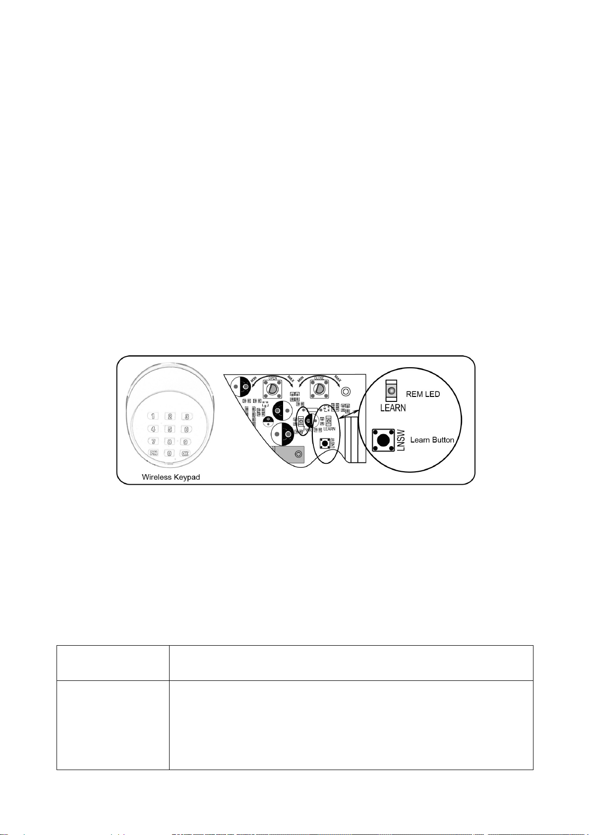
8 Wired Keypad (12VDC) (Optional)
The RED wire of the wired keypad should be connected into the “12” terminal.
The BLACK wire of the wired keypad should be connected into the “13” terminal.
The PURPLE wire of the wired keypad should be connected into the “16” terminal.
The BLUE wire of the wired keypad should be connected into the “15” terminal.