Toro 03713 User manual

FormNo.3392-136RevA
Right/Left-HandGroomerKit
27-inchReelmaster®7000-DDPACutting
Unit
ModelNo.03713
ModelNo.03714
Registeratwww.Toro.com.
OriginalInstructions(EN)*3392-136*A

WARNING
CALIFORNIA
Proposition65Warning
Thisproductcontainsachemicalorchemicals
knowntotheStateofCaliforniatocausecancer,
birthdefects,orreproductiveharm.
Theengineexhaustfromthisproduct
containschemicalsknowntotheStateof
Californiatocausecancer,birthdefects,
orotherreproductiveharm.
ThisproductcomplieswithallrelevantEuropeandirectives.
Fordetails,pleaseseetheDeclarationofIncorporation(DOI)
atthebackofthispublication.
Coveredbyoneormoreofthefollowingpatents:U.S.Patent
7,337,601and7,775,025
Introduction
Thegroomerkitsaremountedtothereelmowersona
ride-onmachineandisintendedtobeusedbyprofessional,
hiredoperatorsincommercialapplications.Itisprimarily
designedforgroominggrassonwell-maintainedlawnsin
parks,sportselds,andoncommercialgrounds.
Readthisinformationcarefullytolearnhowtooperateand
maintainyourproductproperlyandtoavoidinjuryand
productdamage.Youareresponsibleforoperatingthe
productproperlyandsafely.
YoumaycontactTorodirectlyatwww .Toro.comforproduct
safetyandoperationtrainingmaterials,accessoryinformation,
helpndingadealer,ortoregisteryourproduct.
Wheneveryouneedservice,genuineToroparts,oradditional
information,contactanAuthorizedServiceDealerorToro
CustomerServiceandhavethemodelandserialnumbersof
yourproductready.Thenumbersareprintedontheshipping
carton.Writethenumbersinthespaceprovided.
ModelNo.
SerialNo.
Thismanualidentiespotentialhazardsandhassafety
messagesidentiedbythesafetyalertsymbol(Figure1),
whichsignalsahazardthatmaycauseseriousinjuryordeath
ifyoudonotfollowtherecommendedprecautions.
Figure1
1.Safetyalertsymbol
Thismanualuses2otherwordstohighlightinformation.
Importantcallsattentiontospecialmechanicalinformation
andNoteemphasizesgeneralinformationworthyofspecial
attention.
©2014—TheToro®Company
8111LyndaleAvenueSouth
Bloomington,MN554202
Contactusatwww.Toro.com.
PrintedintheUSA.
AllRightsReserved

Contents
Safety...........................................................................3
SafeOperatingPractices...........................................3
Setup............................................................................5
ToolsRequiredforSetup..........................................5
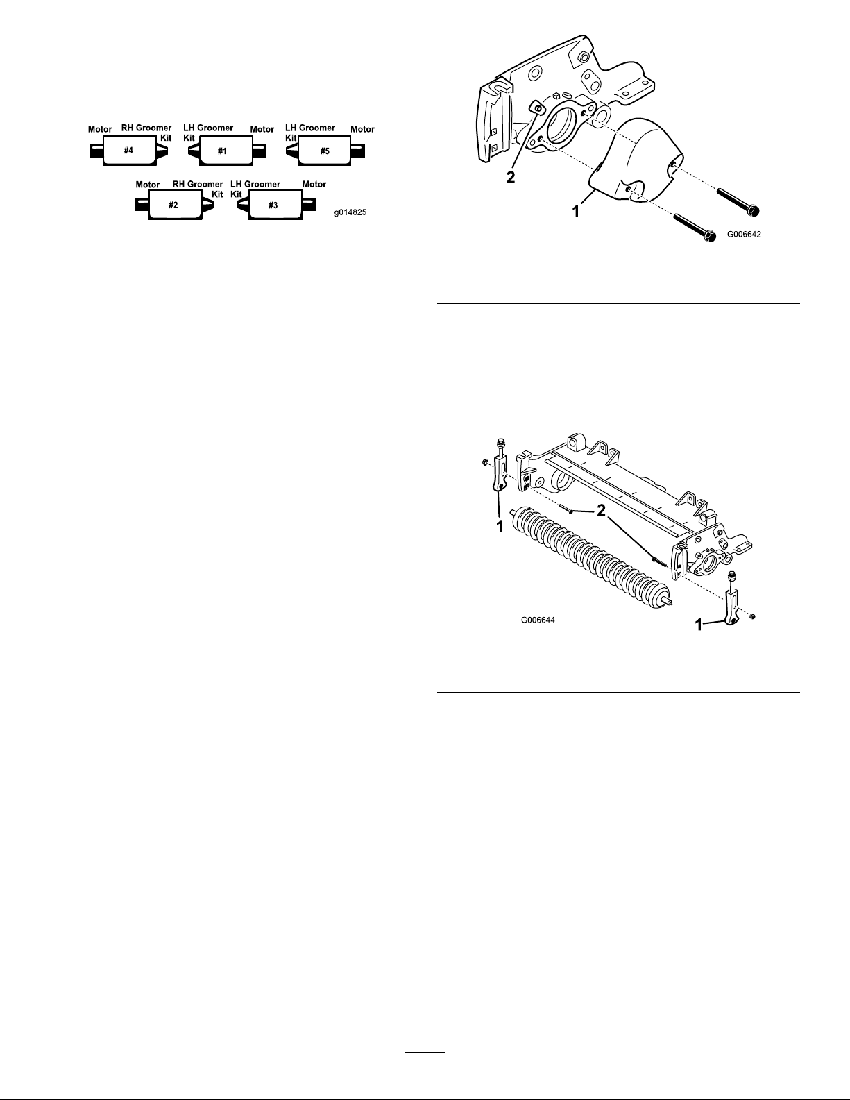
InstallingtheGroomer.............................................6
InstallingtheBroomerKit(optional).........................17
Operation....................................................................18
AdjustingtheGroomerHeight.................................18
TestingtheGroomerPerformance............................20
Maintenance.................................................................21
Cleaning................................................................21
Lubrication............................................................21
InspectingtheBlades..............................................21
GroomerPulley/BeltAlignment..............................21
GroomerBindingTroubleshooting...........................22
Safety
ThismachinehasbeendesignedinaccordancewithENISO
5395:2013.
SafeOperatingPractices
•Read,understand,andfollowallinstructionsinthe
tractionunitandcuttingunitoperatormanualsbefore
operatingthegroomer.
•Read,understand,andfollowallinstructionsinthis
operator’smanualbeforeoperatingthegroomer.
•Neverallowchildrentooperatethecuttingunits.Do
notallowadultstooperatetractionunitorcuttingunits
withoutproperinstruction.Onlytrainedoperatorswho
havereadthismanualshouldoperatethecuttingunits.
•Neveroperatethecuttingunitswhenundertheinuence
ofdrugsoralcohol.
•Keepallshieldsandsafetydevicesinplace.Ifashield,
safetydeviceordecalisillegibleordamaged,repairor
replaceitbeforeoperationiscommenced.Alsotighten
anyloosenuts,bolts,andscrewstoensurecuttingunitis
insafeoperatingcondition.
•Alwayswearsubstantial,slip-resistantfootwear.Donot
operatecuttingunitwhilewearingsandals,tennisshoes,
sneakersorshorts.Also,donotwearloosettingclothing
whichcouldgetcaughtinmovingparts.Alwayswear
longpantsandsubstantialshoes.Wearingsafetyglasses,
safetyshoesandahelmetisadvisableandrequiredby
somelocalordinancesandinsuranceregulations.
•Removealldebrisorotherobjectsthatmightbepicked
upandthrownbythecuttingunitblades.Keepall
bystandersawayfromthemowingarea.
•Ifthebladesstrikeasolidobjectorthecuttingunit
vibratesabnormally,stopandshuttheengineoff.Check
cuttingunitfordamagedparts.Repairanydamagebefore
restartingandoperatingthecuttingunit.
•Lowerthecuttingunitstothegroundandremovekey
fromignitionswitchwhenevermachineisleftunattended.
•Besurecuttingunitsandgroomersareinsafeoperating
conditionbykeepingnuts,boltsandscrewstight.
•Removekeyfromignitionswitchtopreventaccidental
startingoftheenginewhenservicing,adjustingorstoring
themachine.
•Lightningcancausesevereinjuryordeath.Iflightning
isseenorthunderisheardinthearea,donotoperate
themachine;seekshelter.
•Performonlythosemaintenanceinstructionsdescribedin
thismanual.Ifmajorrepairsareeverneededorassistance
isdesired,contactanAuthorizedToroDistributor.
•Toensureoptimumperformanceandsafety,always
purchasegenuineTororeplacementpartsandaccessories
tokeeptheToroallToro.Neveruse“will-t”
replacementpartsandaccessoriesmadebyother
manufacturers.LookfortheTorologotoassure
3

genuineness.Usingunapprovedreplacementpartsand
accessoriescouldvoidthewarrantyofTheToro®
Company.
4

Setup
LooseParts
Usethechartbelowtoverifythatallpartshavebeenshipped.
DescriptionQty.Use
45degreegreasetting1
Heightofcutbracketassembly,R.H.1
Heightofcutbracketassembly,L.H.1
Flangelocknut,3/8inch2
Splinedinsert1
Groomershaftassembly1
Shimwasher(asrequiredforbeltalignment)1
Socketheadscrews,3/8x1inch4
Groomerbelt1
Idlerspring1
Rubbergrommetring(usedonlyifrearroller
brushkitisinstalled)1
Setscrew(usedonlyifrearrollerbrushkitis
installed)1
Operator’sManual1
PartsCatalog1
InstalltheGroomer
Nopartsrequired–InstalltheBroomerKit(optional)
TractionUnitRequirements
TheRightandLeftGroomerKitModels03713and03714
canbeusedonReelmaster7000-DDPACuttingUnitModels
03710and03711withorwithoutaRearRollerBrushKit.
Note:Determinetheleftandrightsidesofthemachine
fromthenormaloperatingposition.
ToolsRequiredforSetup
•5/16socket
•1/2deep–wellsocket
•9/16deep-wellsocket
•5/8socket
•3/8wrench
•1/2wrench
•9/16wrench(2)
•5/16Allenwrench
•5/32mmAllenwrench
•3/8-16tap
•Needlenosepliers
•6inchruler,ToroPartNo.114–5446
•12inchstraightedge
•Flatscrewdriver
•Viseclamppliers
•Torquewrench15-19ft-lb(20-26N-m)
•Torquewrench27-33ft-lb(36-45N-m)
•Torquewrench34-40ft-lb(46-54N-m)
•Torquewrench85-95ft-lb(115-129N-m)
•Reeldriveshafttool,PartNo.TOR4074
•Blue242Loctite
5

GroomerKitOrientation
Allcuttingunitsareshippedwiththecounterweightmounted
totheleftendofthecuttingunit.Usethefollowingdiagram
todeterminethepositionofthegroomerkitsandreelmotors.
Figure2
Note:Theseinstructionsandillustrationsshowthe
installationoftheLeftHandGroomerKitontothecutting
unitswiththecounterweightsmountedontheleftendof
thecuttingunit.TheRightHandGroomerKitsaretobe
installedontocuttingunitswiththecounterweightsmounted
ontherightendofthecuttingunit.
Note:Ifagroomerkitandabrushkitaregoingtobe
installedonthecuttingunit,installthegroomerkitrst.
Usethefollowinginstallationinstructionsifthecutting
unitsarenotequippedwithrearrollerbrushes.Ifthe
cuttingunitsareequippedwithrearrollerbrushes,
proceedtopage10fortheinstallationinstructions.
InstallingtheGroomer
ForCuttingUnitsNotEquippedwith
RearRollerBrushes
1.Parkthetractionunitonalevelsurfaceandengagethe
parkingbrake.
2.Ensurethatthecuttingunitsaredisengaged.Lower
thecuttingunitstotheground.Turntheengineoff
andremovethekey.Removeallcuttingunitsfrom
tractionunit.
Note:Makesureallblackplastictiestrapshavebeen
removedfromthegroomerassemblies.
3.Removethe(2)boltssecuringthecounterweightto
theleftendofthecuttingunit.Removethecounter
weight(Figure3).
Figure3
1.Counterweight2.Greasetting
4.Removethestraightgreasettingfromthebearing
housingandreplacewiththe45degreetting(Figure
3).Positionthettingsoitpointstothetopofthe
cuttingunit.
5.Removethecarriageboltsandnutssecuringtheheight
ofcutbracketstothecuttingunitsideplates(Figure4).
Figure4
1.Heightofcutbracket2.Carriagebolt
6.Loosenthescrewssecuringtheheightofcutbrackets
tothefrontrollershaft.
7.Removetheheightofcutbracketsandthefrontroller
fromthecuttingunitsideplates(Figure4).
8.Looselyinstallthenewrightandleftheightofcut
bracketstotheexistingfrontrollerwithnew5/16
x1-1/8inchcapscrewsand5/16inchangehead
locknuts.Positiontheheightofcutbracketsasshown
ingureFigure6.
Note:Theleftheightofcutbracketismarkedwith
an“L”andtherightheightofcutbracketismarked
witha“R”.
9.Usingtheuppersquareholeineachsideplate,loosely
mounttheheightofcutbracketstothecuttingunit
sideplateswiththecarriageboltspreviouslyremoved
and(2)new3/8inchangenuts,positioningasshown
ingureFigure6.
6

Note:Thewashersontheheightofcutadjusting
boltsmustbelocatedoneachsideoftheangeonthe
sideplate(Figure5).
10.Tightenthelocknutontheheightofcutadjusterbolt
untilthewasherscontactthesideplateange,then
back-offthenut1/2turn(Figure5).
Figure5
1.Washer3.Sideplateange
2.Locknut
11.Centertherollerbetweentheheightofcutbrackets
andlockitinplacewiththecapscrewsandlocknuts
onthebrackets(Figure6).
Figure6
1.Heightofcutbracket3.Carriagebolt
2.Capscrew&locknut
12.UsingtheReelDriveShaftTool,removethesplined
insertfromthereelmotorendofthereelshaft(Figure
7).UseReeldriveshafttool,PartNo.TOR4074.
Cleanallthegreaseoutofthethreadedholewherethe
splinedinsertwas.
Important:Thesplinedinsertonthelefthand
sideofthecuttingunithaslefthandthreads.The
splinedinsert,ontherighthandsideofthecutting
unit,hasrighthandthreads.
13.Installthenew(longer)splinedinserttothereelshaft
(Figure7).ApplyblueLoctitetothethreadsofthe
insertpriortoinstallation.Torqueto85-95ft-lb
(115–129N-m).
Figure7
1.Splinedinsert2.Cleanouttheseholes
14.Onthenon-drivesideofthegroomerassembly,slide
thegroomerplatewithquick-upleveroffthegroomer
shaftassembly(Figure9).
15.Usinga3/8-16tap,removethepaintintheouter
mountingholesinboththeleftandrightsideplates
(Figure7).
16.Onthedrivesideofthecuttingunit,mountthepivot
hub,thedrivesidegroomerplatewithquick-uplever
andtheshimtothecuttingunitsideplatewith(2)3/8
x1inchsocketheadscrews(Figure9).Applyblue
Loctitetothescrewthreadspriortoinstallation.
Important:MakesuretheO-ringisproperly
positionedonthepivothub(Figure8).
Figure8
1.O-ring
Important:Makesurethesplinedendofpivot
hubshafttsintothesplinedinsert.
7

Important:Makesurethepivothubmounting
surfaceisushwiththesideplateonthecutting
unit.Theshimmustnotbepinchedbetweenthe
pivothubandthesideplate.
17.Installthenon-drivegroomerplateontothegroomer
shaft(Figure9).Becarefulnottoknockthesealspring
off.
18.Securethenon-drivepivothubtothecuttingunitside
platewith(2)3/8x1inchsocketheadscrews(Figure
9).ApplyblueLoctitetothescrewthreadspriorto
installation.
Figure9
1.Groomershaftassembly7.Shim(mustremainlooseafterinstallation)
2.Groomerplatew/quick-uplever(non-driveend)8.Pivothub(non-driveend)
3.Pivothub(driveend)9.Idlerspring
4.Splinedshaft10.Belt
5.Groomerplatew/quick-uplever(driveend)11.Sealspring
6.Quick-uplever
19.Makesurethesealliponeachexcluderseal,isinlight
contactwitheachbearinghousing(Figure10).
Figure10
1.Excluderseal2.Bearinghousing
8

20.Mountthequick-upleverassembliestothesideplates
with3/8x3/4inchangeheadbolts(Figure9).
21.Installthegroomerbeltontothepulleys(Figure9).
Makesuretheribsonthebeltareproperlyseatedin
thegroovesoneachpulley.
22.Hooktheidlerspringintheholeintheidlerplatetab
andaroundthegrooveonthegroomerplatelowerstud
(Figure11).Theopenendofthespringhookistobe
positionedtowardthedrivepulley.
Figure11
1.Idlerspring3.Lowerstud
2.Idlerplatetab
23.Checkthealignmentofthebelt/pulleysasfollows:
•Layastraightedgealongtheouterfaceofthedrive
pulley(Figure12).
Important:
Do Not
usetheidlerpulleyto
checkalignment.
Figure12
•Theouterfacesofthedriveanddrivenpulleys
shouldbeinlinewithin.030inch(.76mm).
•Ifthepulleysarenotaligned,refertothesection
onPulleyAlignment.
•Ifthepulleysarealigned,continuewiththe
installation.
Important:Thebeltmayfailprematurelyifthe
pulleysarenotproperlyaligned.
24.Installthegroomercoverandsecurewith(2)5/16inch
angenuts(Figure13).
Important:Donotovertightenthenutsas
damagetothecovermayoccur.
Figure13
1.Cover
25.Filleachreelbearinghousingwithgrease(Figure14).
Excessgreasewillpurgebetweentheinboardsealsand
thesealguards.
26.Greaseeachofthegroomerbearings(2or3pumps
maximum)(Figure14).Donotover-greaseasexcess
greasemaycausesealfailure.Wipeoffanyexcess
grease.
Figure14
9

Note:Aftergreasinggroomerbearings,operate
groomerfor30seconds,stopmachineandwipeexcess
greasefromgroomershaftandseals.
27.Adjusttheheightofthegroomer.RefertoAdjusting
GroomerHeight.
ForCuttingUnitsEquippedwithRear
RollerBrushes
1.Parkthetractionunitonalevelsurfaceandengagethe
parkingbrake.
2.Ensurethatthecuttingunitsaredisengaged.Lower
thecuttingunitstotheground.Turntheengineoff
andremovethekey.Removeallcuttingunitsfrom
tractionunit.
3.Removethe(2)rollerbrushcovermountingnutsand
removethecover(Figure15).
Figure15
1.Beltcover
4.Whilerotatingthereel,whichwillrotatethedrive
pulley,prythebeltoffthedrivepulley(Figure16).
G01 1425
1
2
3
Figure16
1.Bearinghousingshaft3.Driverpulley
2.Spacer
Note:Wearapaddedgloveoruseaheavyragto
rotatethereel.
Note:Iftheidlerpulleyisxed,releasethebelt
tensionbylooseningthenutsecuringtherollerbrush
idlerpulleytotherollerbrushpivotplate.Donot
removethenut.
5.Removetheboltsecuringtherollerbrushdrivepulley
tothebearinghousingshaft(Figure16).
6.Removetherollerbrushdrivepulleyandthespacer
fromtheshaft(Figure16).
7.Removethe(2)capscrewssecuringtherollerbrush
pivotplatetothebearinghousing(Figure17).
Figure17
1.Shoulderbolt5.Rollerbrushmounting
bracket
2.Brushplate6.Flangelocknuts
3.Capscrew7.Rollerbrushbearing
housing
4.Grommetinbearing
housing
8.Removetheshoulderboltsecuringtherollerbrush
pivotplatetothebearinghousing(Figure17).
9.Removethepivotplatewithidlerpulleyassemblystill
attached(Figure17).
10.Removethe(2)screwssecuringthebearinghousingto
thecuttingunitsideplate(Figure18).
11.Removethebearinghousingfromthesideplate(Figure
18).
10

Figure18
1.Bearinghousing
12.Removethecarriageboltsandnutssecuringtheheight
ofcutbracketstothecuttingunitsideplates(Figure
19).
13.Loosenthecapscrewsandlocknutssecuringtheheight
ofcutbracketstothefrontrollershaft(Figure19).
14.Removetheheightofcutbracketsandthefrontroller
fromthecuttingunitsideplates(Figure19).
Figure19
1.Heightofcutbracket2.Carriagebolt
15.Looselyinstallthenewrightandleftheightofcut
bracketstotheexistingfrontrollerwithnew5/16
x1-1/8inchcapscrewsand5/16inchangehead
locknuts.Positiontheheightofcutbracketsasshown
ingureFigure20.
Note:Theleftheightofcutbracketismarkedwith
an“L”andtherightheightofcutbracketismarked
witha“R”.
Figure20
1.Heightofcutbracket3.Carriagebolt
2.Capscrew&locknut
16.Usingtheuppersquareholeineachsideplate,loosely
mounttheheightofcutbracketstothecuttingunit
sideplateswiththecarriageboltspreviouslyremoved
andnew3/8inchangenuts,positioningasshown
ingureFigure20.
Note:Thewashersontheheightofcutadjusting
boltsmustbelocatedoneachsideoftheangeonthe
sideplate(Figure21).
Figure21
1.Washer3.Sideplateange
2.Locknut
17.Tightenthelocknutontheheightofcutadjusterbolt
untilthewasherscontactthesideplateange,then
back-offthenut1/2turn(Figure21).
18.Centertherollerbetweenthebracketsandlockin
placewiththecapscrewsandlocknutsonthebrackets
(Figure20).
19.UsingtheReelDriveShaftTool,removethesplined
insertfromthereelmotorendofthereelshaft(Figure
22).UseReeldriveshafttool,PartNo.TOR4074.
11

Cleanallthegreaseoutofthethreadedholewherethe
splinedinsertwas.
Important:Thesplinedinsertonthelefthand
sideofthecuttingunithaslefthandthreads.The
splinedinsert,ontherighthandsideofthecutting
unit,hasrighthandthreads.
Figure22
1.Splinedinsert2.Cleanouttheseholes
20.Installthenew(longer)splinedinserttothereelshaft
(Figure22).ApplyblueLoctitetothethreadsof
theinsertpriortoinstallation.Torqueto85-95ft-lb
(115-129N-m).
21.Onthenon-drivesideofthegroomerassembly,slide
thegroomerplateoffthegroomershaftassembly
(Figure24).
22.Usinga3/8-16tap,removethepaintintheouter
mountingholesinboththeleftandrightsideplates
(Figure23).
23.Onthedrivesideofthecuttingunit,mountthepivot
hub,thedrivesidegroomerplateandtheshimtothe
cuttingunitsideplatewith(2)3/8x1inchsockethead
screws(Figure24).ApplyblueLoctitetothescrew
threadspriortoinstallation.
Important:MakesuretheO-ringisproperly
positionedonthepivothub(Figure23).
Figure23
1.O-ring
Important:Makesurethesplinedendofpivot
hubshafttsintothesplinedinsert.
Important:Makesurethepivothubmounting
surfaceisushwiththesideplateonthecutting
unit.Theshimmustnotbepinchedbetweenthe
pivothubandthesideplate.Theshimmustbe
abletopivotfreely.
24.Installthenon-drivegroomerplateontothegroomer
shaft(Figure24).Becarefulnottoknocktheseal
springoff.
12

Figure24
1.Groomershaftassembly7.Shim(mustremainlooseafterinstallation)
2.Groomerplatew/quick-uplever(non-driveend)8.Pivothub(non-driveend)
3.Pivothub(driveend)9.Idlerspring
4.Splinedshaft10.Belt
5.Groomerplatew/quick-uplever(driveend)11.Sealspring
6.Quick-uplever
25.Securethenon-drivepivothubtothecuttingunitside
platewith(2)3/8x1inchscrews(Figure24).Apply
blueLoctitetothescrewthreadspriortoinstallation.
26.Makesurethesealliponeachexcluderseal,isinlight
contactwitheachbearinghousing(Figure25).
Figure25
1.Excluderseal2.Bearinghousing
27.Mountthequick-upleverassembliestothesideplates
with3/8x3/4inchangeheadbolts(Figure24).
28.Installthegroomerbeltontothepulleys(Figure24).
Makesuretheribsonthebeltareproperlyseatedin
thegroovesoneachpulley.
29.Hooktheidlerspringintheholeintheidlerplatetab
andaroundthegrooveonthegroomerplatelowerstud
(Figure26).Theopenendofthespringhookistobe
positionedtowardthedrivepulley.
13

Figure26
1.Idlerspring3.Lowerstud
2.Idlerplatetab
30.Checkthealignmentofthebelt/pulleysasfollows:
•Layastraightedgealongtheouterfaceofthedrive
pulley(Figure27).
Important:
Do Not
usetheidlerpulleyto
checkalignment.
Figure27
•Theouterfacesofthedriveanddrivenpulleys
shouldbeinlinewithin.030inch(.76mm).
•Ifthepulleysarenotaligned,refertothesection
onPulleyAlignment.
•Ifthepulleysarealigned,continuewiththe
installation.
Important:Thebeltmayfailprematurelyifthe
pulleysarenotproperlyaligned.
31.Removethe(2)5/16inchangenutssecuringthe
groomerweighttothegroomercoverandremovethe
weight(Figure28).
Figure28
1.Groomerweight4.Rubbergrommetring
2.Groomercover5.Coverscrews(remove)
3.Solidgrommet6.Setscrew(2)
32.Removethesolidgrommetfromthecoverandreplace
itwiththerubbergrommetring(Figure28).
33.Removethe(2)5/16x1-1/4screwsthreadedintothe
cover(Figure28).
34.Removethesetscrewfromthecenterholeinthe
groomercover(Figure28).Installthissetscrewand
thesetscrew ,includedwiththekit,intotheholes
previouslyusedforthecovermountingscrews.Apply
Loctitetothesetscrewspriortoinstallation.Makesure
thesetscrewsareushwiththecover.
35.Installthegroomercoverandsecurewith(2)5/16inch
angenuts(Figure29).
Important:Donotovertightenthenuts.
Figure29
1.Groomercover2.Grommet
14

36.Applyalmofgreasetotheinsidediameterofthe
grommetinthegroomercover(Figure29).
37.Loosentheboltssecuringtherollerbrushbearing
housingtotherollerbrushmountingbracket(Figure
30).
38.Installtherollerbrushpivotplate(Figure30).When
theprotrusiononthepivotplateisinsertedintothe
grommetonthegroomercover,makesurethatthe
grommetstaysproperlyseatedonthecover.
G01 1426
6
4
7
5
1
2 3
Figure30
1.Shoulderbolt5.Rollerbrushmounting
bracket
2.Brushplate6.Flangelocknuts
3.Capscrew7.Rollerbrushbearing
housing
4.Grommetinbearing
housing
39.Apply242Loctite(blue)tothe(2)5/16x5/8inch
capscrewsandusethemtomountthebrushplateto
therollerbrushbearinghousing(Figure30).Torque
thecapscrewsto15-19ft-lb(20–26N-m).
40.Checktomakesuretherollerbrushplateisparallelto
thecuttingunitsideplate.Ifitisnotparallel,proceed
asfollows:
•Loosenthe(2)angelocknutssecuringtheroller
brushmountingbrackettothecuttingunitside
plate(Figure30).
•Rotatetherollerbrushbearinghousinguntilthe
brushplateisparalleltothecuttingunitsideplate
(Figure30).
•Tightenthe(2)angelocknutssecuringtheroller
brushmountingbrackettothecuttingunitside
plate(Figure30).
41.Apply242Loctite(blue)totheshoulderbolt(Figure
30).Mountthebrushplatetothegroomercoverwith
theshoulderbolt.(Fig.29).Torquetheboltto15-19
ft-lb(20–26N-m).
42.Removetheboltsecuringthegroomerpulleytothe
driveshaft(Figure31).
43.Insertthebrushdrivepulleyintothegroomerdrive
pulleyandontothedriveshaft(Figure31).Makesure
thepulleytabsarepositionedintheslotinthedrive
shaft.
44.ApplyLoctitetothethreadsofthe3/8x2inchange
headbolt.Securethedrivepulleytotheshaftwiththe
angeheadbolt(Figure31).Torquetheboltto34-40
ft-lb(46–54N-m).
G01 1427
1
2
3
Figure31
1.Groomerpulleymounting
bolt(remove)
3.Belt
2.Drivepulley
45.Installthebeltontothepulleysandspringloadedidler
asfollows:
•Loopthebeltaroundthedrivenpulleyandthen
overthetopoftheidlerpulley(Figure32).
Figure32
1.Drivepulley3.Drivenpulley
2.Idlerpulleyassembly4.Belt
•Startthebeltonthedrivepulley(Figure32).
•Whileguidingthebeltontothedrivepulley,rotate
thereelforwardtodrawthebeltontothedrive
pulley.
Note:Wearapaddedgloveoruseaheavyragto
rotatethereel.
Important:Makesuretheribsonthebeltare
properlyseatedinthegroovesineachpulley.Also,
makesurethebeltisinthecenteroftheidler
pulley.
15

46.Pushdownontheidlerpulleytoensurethattheidler
pulleyassemblypivotsfreely.
47.Checkthealignmentofthebelt/pulleysasfollows:
•Layastraightedgealongtheouterfaceofthedrive
pulley(Figure33).
G01 1428
Figure33
•Theouterfacesofthedriveanddrivenpulleys
shouldbeinlinewithin.030inch(.76mm).
•Ifthepulleysarenotaligned,Refertothesection
onPulleyAlignment.
•Ifthepulleysarealigned,continuewiththe
installation.
•DoNotusetheidlerpulleytocheckalignment.
Important:Thebeltmayfailprematurelyifthe
pulleysarenotproperlyaligned.
48.Slidethebeltcoverontothemountingboltsandsecure
with(2)angenuts(Figure34).
Important:Donotovertightennutsasdamage
tocovermayoccur.
Figure34
1.Beltcover
49.Filleachreelbearinghousingwithgrease(Figure35).
Excessgreasewillpurgebetweentheinboardsealsand
thesealguards.
G01 1429
Figure35
50.Greaseeachofthegroomerbearings(2or3pumps
maximum)(Figure35).Donotover-greaseasexcess
greasemaycausesealfailure.Wipeoffanyexcess
grease.
Note:Aftergreasinggroomerbearings,operate
groomerfor30seconds,stopmachineandwipeexcess
greasefromgroomershaftandseals.
51.Adjusttheheightofthegroomer.RefertoAdjusting
GroomerHeight.
16

InstallingtheBroomerKit
(optional)
1.Fromonesideofthegroomerreel,slideabrushinto
eachgroovearoundthefulllengthofthegroomerreel
(Figure36).
Figure36
1.Brush2.Strap
2.Verifythatthebrushesareseatedinthegroomerblade
slots(Figure37&Figure38).
3.Looselywrapthestraps,asshowninFigure38,around
thegroomerreelshaftandbrushesinsertingthestraps
inthegroovesinthebrushesFigure37Positionthe
brushessothestrapsarebetweenthefollowingblades
1-2,14-15,28-29and41-42.
Figure37
1.Brush2.Blade
Important:Thestrapsmustbewrappedaround
thegroomerbladeandbrushassemblyinthe
correctdirection.
Note:Ifthebroomerbrushesarenotseatedproperly
inthebladeslots,loosenthegroomerbladeretaining
nutsoneachendofthegroomershaft,positionthe
broomerbrushesproperlyinthebladeslotsandtighten
thegroomerbladeretainingnuts(Figure38).
4.Whilepushingascrewdriveragainstthestrapbuckle,
graspthestrapwithavicegrippliersandpullthestraps
tightuntiltheylockinthebrushgrooves(Figure38).
Figure38
1.Brush3.Retainingnut(2)
2.Strap4.Strapbuckle
5.Trimoffthestraptoapproximately1/4inchfrom
thebuckleandfoldtheexcessstrapoverthebuckle
(Figure38)
17

Operation
Groomingisperformedintheturfcanopyabovethesoil
level.Groomingpromotesverticalgrowthofgrassplants,
reducesgrainandseversstolonsproducingadenserturf.
Groomingproducesamoreuniformandtighterplaying
surfaceforfasterandtrueractionofthegolfball.
Verticuttingisamoreaggressivecultivationtechnique
designedtoremovethatchbycuttingthroughtheturfcanopy
andintothethatch/matlayer.Groomingshouldnotbe
consideredareplacementforverticutting.Verticuttingis
generallyamorerigorousandperiodictreatmentthatcan
temporarilydamagetheplayingsurface,whilegroomingisa
routineandgentlertreatmentdesignedtomanicuretheturf.
Figure39
1.Grassrunners(stolons)2.Thatch
Groomingbrushesareamorerecentdevelopmentwhich
aredesignedtobelessintrusivethanconventionalgrooming
bladeswhenadjustedtolightlycontacttheturfcanopy.
Brushingmaybemorebenecialfortheultra-dwarfcultivars,
sincethesegrasstypeshavemoreofauprightgrowthpattern
anddonotllinthatwellthroughhorizontalgrowth.
Brushes,however,caninjureleaftissueiftheyaresetto
penetratetoodeeplyintothecanopy.
Groomingissimilartoverticuttinginitsrunnercutting
action.Groomingbladeshowever,shouldneverpenetrate
thesoillikeverticuttingordethatching.Groomerblades
arespacedclosertogetherandareusedmoreoftenthan
verticutterssothattheyaremoreeffectiveincuttingrunners
andremovingthatch.
Becausegroominginjuresleaftissuetosomedegreeitshould
beavoidedduringperiodsofhighstress.Coolseasonspecies
suchascreepingbentgrassandannualbluegrassshouldnot
begroomedduringhightemperature(andhighhumidity)
periodsinmidsummer.
Itisdifculttomakespecicrecommendationsonthe
useofgroomingreelsbecausesomanyvariablesaffectthe
performanceofgrooming,including:
•Thetimeoftheyear(i.e.,thegrowingseason)and
weatherpattern
•Thegeneralconditionofeachfairway
•Thefrequencyofgrooming/cutting—bothhowmany
cuttingsperweekandhowmanypassespercutting
•Theheightofcutsettingonthemainreel
•Theheight/depthsettingonthegroomingreel
•Howlongthegroomingreelhasbeeninuse
•Thetypeofgrass
•Theoverallmanagementprogram(i.e.irrigation,
fertilizing,spraying,coring,overseeding,etc.)
•Thetrafconthefairway
•Stressperiods(i.e.,hightemperatures,highhumidity,
unusuallyhightrafc)
Thesefactorscanvaryfromgolfcoursetogolfcourse.It
isimportant,therefore,toinspectthefairwaysfrequently
andvarythegroomingpracticeinaccordancewiththe
need.
Note:Thepracticeofchangingthedirectionofcuteach
timethefairwayiscutshouldbecontinuedwhenagroomeris
used.Thisrotationwillenhancetheeffectsofthegrooming.
Note:Improperoroveraggressiveuseofthegroomer
reel(i.e.toodeeportoofrequentgrooming)maycause
unnecessarystressoftheturfleadingtosevereturfdamage.
Usethegroomercautiously.
Note:Operatethegroomerinastraightlineasmuchas
possible.Usecautionwhenturningwhileoperatinggroomer.
AdjustingtheGroomerHeight
1.Parkthemachineonacleanandlevelsurface,lower
thecuttingunitscompletelytotheground,stopthe
engine,engagetheparkingbrakeandremovethekey
fromtheignitionswitch.
2.Makesuretherollersarecleanandcuttingunitissetto
thedesiredheight-of-cut(seeCuttingUnitOperator’s
Manual).
3.Rotatethequick-uplevers(Figure40)totheEngaged
Position(handlepointstowardthefrontofthecutting
unit.UseHeightofCut(HOC)andHeightof
Groom(HOG)recommendedrangechartfor
settingthegaugebar.
4.Ononeendofthegroomerreel,measurethedistance
fromthelowesttipofthegroomerbladetothe
workingsurface(Figure40).Turnheightadjusterknob
(Figure40)toraiseorlowerthegroomerbladetipto
thedesiredheight.
18

Figure40
1.Quick-uplever(engaged
position)
3.Heightadjusterknob
2.Groomerheight(HOG)4.Numberofrearroller
spacers(belowsideplate
pad)
5.Repeatstep4ontheoppositeendofthegroomer.
Then,recheckthesettingontherstsideofgroomer.
Heightsettingonbothendsofthegroomershouldbe
identical.Readjustasrequired.
Important:Afteradjustingtheheightofthe
groomer,adjustthejamnutsonthreadedrod,
sothespringsare1-3/8inch(3.5cm)longwhen
thegroomerleversareinthedisengagedposition
(handlepointedtowardsrearofcuttingunit)
(Figure41).
Note:1-3/8inches(3.5cm)isthedistancefrom
thetopofthejamnuttothebottomofthegroomer
mountingbracket.
Figure41
19

HeightofCut(HOC)andHeightofGroom(HOG)RecommendedRange
HeightofCutNumberofRearRoller
Spacers
RecommendedHOG=HOC-GroomerEngagement
.250inch(6.4mm)0.125-.250(3.1–6.4mm)
.375inch(9.5mm)
.375inch(9.5mm)
0
1
.187-.375(4.7–9.5mm)
.500inch(12.7mm)
.500inch(12.7mm)
.500inch(12.7mm)
0
1
2
.250-.500(6.4–12.7mm)
.250-.375(6.4–9.5mm)
.625inch(15.8mm)
.625inch(15.8mm)
.625inch(15.8mm)
0
1
2
.375-.625(9.5–15.8mm)
.375-.500(9.5–12.7mm)
.75inch(19mm)
.750inch(19mm)
.750inch(19mm)
1
2
3
.500-.750(9.5–15.8mm)
.500-.625(9.5–12.7mm)
.875inch(22.2mm)
.875inch(22.2mm)
.875inch(22.2mm)
1
2
3
.625-.875(15.8–22.2mm)
.625-.750(15.8–19mm)
1.00inch(25.4mm)
1.00inch(25.4mm)
1.00inch(25.4mm)
2*
3
4
.750-1.00(19–25.4mm)
.750-.875(19–22.2mm)
Note:MaximumHOGrecommendedishalftheHOCto
0.25inch(6.4mm)Maximumengagement
*Movegroomerfrontheightofcut(HOC)brackettothe
bottom(cuttingunitlocation)sideplatehole
TestingtheGroomer
Performance
Important:Improperoroveraggressiveuseofthe
groomingreel(i.e.,toodeeportoofrequentgrooming)
maycauseunnecessarystressontheturfleadingto
severedamage.Usethegroomercautiously.
DANGER
Contactwiththereelsorothermovingpartscan
resultinpersonalinjury.
•Beforemakinganyadjustmentstothecutting
units,disengagethereels,settheparkingbrake,
stoptheengine,andremovetheignitionkey.
•Keepngers,hands,andclothingawayfromthe
reelsorothermovingparts.
Itisimportanttodeterminetheperformanceofthegroomer
beforeputtingitintoregularuse.
Wesuggestthataformaltestprocedurebeused.The
followingisapracticalwayofdeterminingtheproper
height/depthsetting:
1.Setthemaincuttingreelstotheheightofcutthat
wouldnormallybeusedwithoutthegroomingreel.
UseaWiehlerolleronthefrontandafullrolleron
therear.
2.Seteachofthegroomingreelstothedesiredheight
setting.
3.Examinethetestareaanddetermineifthegroomed
areasgivesthedesiredresults.Ifnot,increaseor
decreasetheheightofthegroomers,andmakeanother
testpass.Theamountofgrassremovedisakey
indicatorindeterminingtheheight/depthsettingof
thegroomingreel.
Checkthetestarea2or3daysaftertherstgroomingfor
generalcondition/damage.Ifthegroomedareasareturning
yellow/brown,andthenon-groomedareasaregreen,then
thegroomingwastooaggressive.
20
This manual suits for next models
1
Table of contents
Other Toro Lawn Mower Accessories manuals

Toro
Toro 32in Recycler 30118 User manual

Toro
Toro 121-8032 User manual

Toro
Toro 59187 User manual

Toro
Toro 04063 User manual

Toro
Toro Z Master 74060 Quick start guide

Toro
Toro 59192 User manual

Toro
Toro Greensmaster eFlex 1018 User manual

Toro
Toro Recycler Kit 131-4184 User manual

Toro
Toro 79395 User manual

Toro
Toro 140-8016 User manual