manuals.online logo
Brands
  1. Home
  2. •
  3. Brands
  4. •
  5. Toro
  6. •
  7. Lawn Mower Accessories
  8. •
  9. Toro 105-3848 User manual

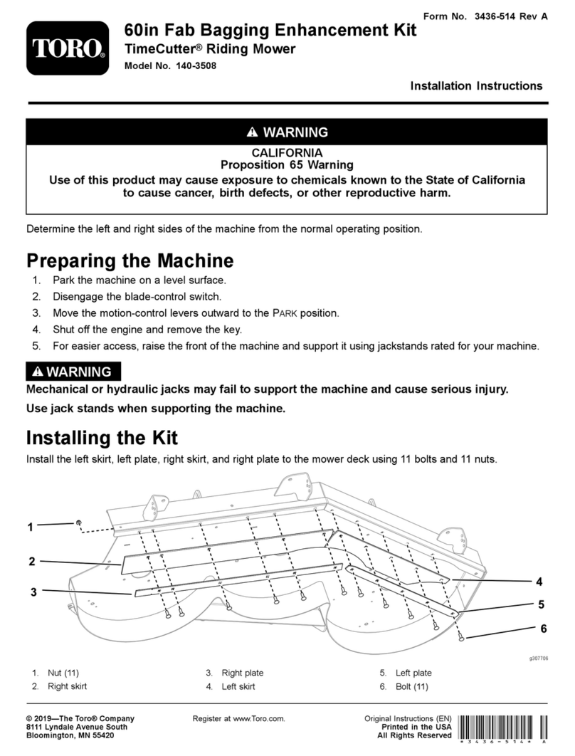
Toro 105-3848 User manual

Other Toro Lawn Mower Accessories manuals

Toro 142-7070 User manual

Toro

Toro 142-7070 User manual

Toro 30460 User manual

Toro

Toro 30460 User manual

Toro 31213 User manual

Toro

Toro 31213 User manual

Toro 30107 User manual

Toro

Toro 30107 User manual

Toro 106-2643 User manual

Toro

Toro 106-2643 User manual

Toro 100-2863 User manual

Toro

Toro 100-2863 User manual

Toro 79413 User manual

Toro

Toro 79413 User manual

Toro 31321 User manual

Toro

Toro 31321 User manual

Toro 04294 User manual

Toro

Toro 04294 User manual

Toro 161-4520 User manual

Toro

Toro 161-4520 User manual

Toro 79174 User manual

Toro

Toro 79174 User manual

Toro 30124 User manual

Toro

Toro 30124 User manual

Toro 31329 User manual

Toro

Toro 31329 User manual

Toro 108-1382 User manual

Toro

Toro 108-1382 User manual

Toro 3200 User manual

Toro

Toro 3200 User manual

Toro 78490 User manual

Toro

Toro 78490 User manual

Toro 3200 User manual

Toro

Toro 3200 User manual

Toro Greensmaster Flex 04853 User manual

Toro

Toro Greensmaster Flex 04853 User manual

Toro GrandStand 133-1438 User manual

Toro

Toro GrandStand 133-1438 User manual

Toro 78534 User manual

Toro

Toro 78534 User manual

Toro 139-6655 User manual

Toro

Toro 139-6655 User manual

Toro ProStripe 560 User manual

Toro

Toro ProStripe 560 User manual

Toro Groundsmaster e3200 User manual

Toro

Toro Groundsmaster e3200 User manual

Toro 95-7067 User manual

Toro

Toro 95-7067 User manual

Popular Lawn Mower Accessories manuals by other brands

Ariens 891008 Operator's manual

Ariens

Ariens 891008 Operator's manual

Rover 108 - 109 owner's manual

Rover

Rover 108 - 109 owner's manual

Snapper 1690047 Operator's manual

Snapper

Snapper 1690047 Operator's manual

RHINO 800 Operator's manual

RHINO

RHINO 800 Operator's manual

Exmark Quest 126-7506 Operator's manual

Exmark

Exmark Quest 126-7506 Operator's manual

Snapper 1685167 installation instructions

Snapper

Snapper 1685167 installation instructions

Cub Cadet 19B70029100 installation manual

Cub Cadet

Cub Cadet 19B70029100 installation manual

Stihl AMK 043.1 instruction manual

Stihl

Stihl AMK 043.1 instruction manual

MTD 753-0873 Service kit manual

MTD

MTD 753-0873 Service kit manual

Bush Hog RG60 Operator's manual

Bush Hog

Bush Hog RG60 Operator's manual

Scag Power Equipment GC-F4 Operator's manual

Scag Power Equipment

Scag Power Equipment GC-F4 Operator's manual

Land Pride RCF2760 Operator's manual

Land Pride

Land Pride RCF2760 Operator's manual

Peco SPARTAN RZ Series Operator's manual

Peco

Peco SPARTAN RZ Series Operator's manual

Peco 28621206 Operator's manual

Peco

Peco 28621206 Operator's manual

Simplicity 367 Operator's manual

Simplicity

Simplicity 367 Operator's manual

Simplicity 211 Operator's manual

Simplicity

Simplicity 211 Operator's manual

Iseki SSM72 Operators & service manual

Iseki

Iseki SSM72 Operators & service manual

Simplicity 1690043 Operator's manual

Simplicity

Simplicity 1690043 Operator's manual

manuals.online logo
manuals.online logoBrands
  • About & Mission
  • Contact us
  • Privacy Policy
  • Terms and Conditions

Copyright 2025 Manuals.Online. All Rights Reserved.

 2004—TheToro Company
8111 Lyndale Ave., Bloomington, MN 55420, USA Printed in the USA
All Rights Reserved Original Instructions (EN)
Register your product at www.Toro.com
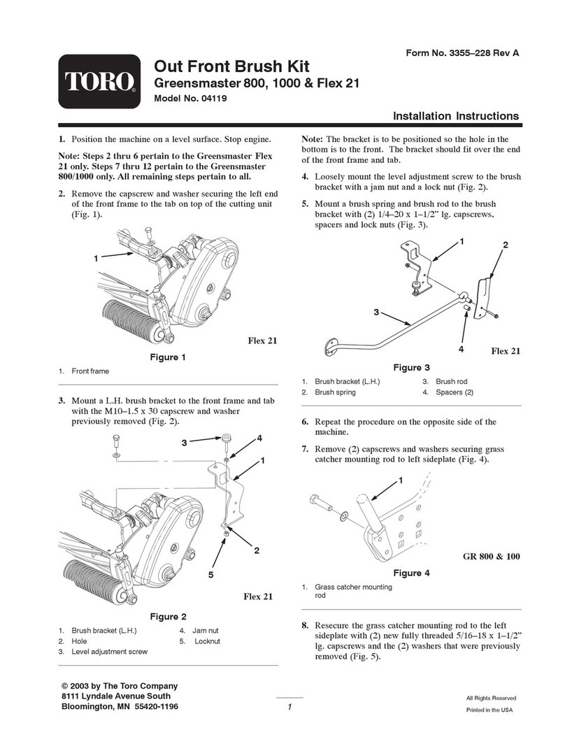
Light Kit
Greensmaster3050 and 3100
Part No. 105-3848
Form No. 3327-362 Rev A
Installation Instructions
Preparing the Traction Unit
If you leave the key in the ignition switch,
someone could accidently start the engine and
seriously injure you or other bystanders.
Remove the key from the ignition and disconnect
the wire(s) from the spark plug(s) before you do
any maintenance. Set the wire(s) aside so that it
does not accidentally contact the spark plug(s).
Caution
1. Disconnect the negative (–) battery cable from the
battery.
2. Remove the left cover plate (Fig. 1).
1
3
2
Figure 1
1. Left cover plate
2. Lockout bracket 3. Rear bolt
3. Remove and discard the rear bolt securing the lockout
bracket to the frame (Fig. 1). Save the washer and
locknut.
4. Remove the cover shield from the side of the control
panel (Fig. 2).
1
2
Figure 2
1. Cover shield 2. Control panel
Installing the Light Switch
(Greensmaster 3050 only)
1. Remove the plastic plug from the control panel
(Fig. 3).
1
Figure 3
1. Plastic plug
2
2. Install the light switch into the control panel, securing
it with 2 nuts and a lockwasher (Fig. 4).
1
2
Figure 4
1. Lightswitch 2. Control panel
3. Under the control panel, locate a blue wire with a clear
protective covering over the terminal that is not
connected to anything and remove the protective
covering.
4. Connect the blue wire to one of the two leads on the
light switch.
Installing the Lights
1. Mark and drill 2 holes (11/32 in. dia.) through both
walls of the mow pedal guard at the locations
indicated in Figure 5.
m-5811
3
2
1
4
Figure 5
1. 3-1/2 in. (8.9 cm)
2. 10 in. (25.4 cm) 3. 1 in. (2.5 cm)
4. Drill holes (11/32 in. dia.)
2. Route the wire harness through the tubular light
bracket so that the connectors on the harness for the
lights are on either end of the bracket (Fig. 6).
m–5810
2
3
3
1
Figure 6
1. Tubularlight bracket
2. Wire harness 3. Connectors
3. Install the light bracket to the front of the mow pedal
guard (Fig. 7), using 2 bolts (5/16 x 2-1/2 in.) and nuts
(5/16 in.).
1
2
3
4
4
Figure 7
1. Tubularlight bracket
2. Mow pedal guard 3. Bolts, 5/16 x 2-1/2 in.
4. Light assemblies
4. Loosely mount a light to each end of the tubular
bracket with a lockwasher and nut (Fig. 7).
3
5. Loosely install an R-clamp, bolt (3/8 x 3 in.), and
washer in the rear hole of the lockout bracket using the
hardware you removed previously (Fig. 8).
3
1
2
44
4
5
Figure 8
1. Wire harness
2. R-clamp
3. Bolt, 3/8 x 3 in.
4. Cable tie
5. Washer
6. Route the harness through the R-clamp, under the left
cover plate and up under the control panel (Fig. 8).
7. Tighten the R-clamp bolt and secure the harness to the
frame using cable ties as needed (Fig. 8).
8. Connect the orange wire of the harness to the open
terminal on the light switch.
9. Connect the black wire to the ground bolt on the frame
(Fig. 9).
2
1
Figure 9
1. Controlpanel 2. Ground bolt
10.Connect the harness to the connectors on both lights.
11. Install all removed covers and plates.
12.Connect the negative (–) battery cable to the battery.
13.Turn on the lights.
14.Aim the lights as desired and then tighten the
mounting nuts to secure them in the desired positions.
Note: Use the lights only while the engine is operating
at or near maximum speed in order to keep the battery
charged.