Toro 04260 User manual

FormNo.3396-481RevB
Counter-RotatingGroomerDriveSystem
DPACuttingUnitsforGreensmaster®Flex™1800/2100,eFlex®
1800/2100,andTriFlex®3300/3400SeriesTractionUnit
ModelNo.04260
InstallationInstructions
ThisproductcomplieswithallrelevantEuropeandirectives.Fordetails,pleaseseetheDeclarationof
Incorporation(DOI)atthebackofthispublication.
WARNING
CALIFORNIA
Proposition65Warning
ThisproductcontainsachemicalorchemicalsknowntotheStateofCalifornia
tocausecancer,birthdefects,orreproductiveharm.
Note:Kit120–2760isrequiredwhenusingthiskiton
aTriFlexwithanelectricreel.ContactyourAuthorized
ToroDistributorformoreinformation.
Thefollowinggroomerreelsarealsoavailableforthis
product:
•18-inchcarbidegroomer
•18-inchspiralbrush
•18-inchsoftgroomingbrush
•18-inchstiffgroomingbrush
•18-inchspring-steelgroomer
•18-inchthin-spring-steelgroomer
•21-inchspringsteelgroomer
•21-inchcarbidegroomer
•21-inchspiralbrush
•21-inchsoftgroomingbrush
•21-inchstiffgroomingbrush
•21-inchthin-spring-steelgroomer
ContactyourauthorizedTorodistributorformore
information.
©2017—TheToro®Company
8111LyndaleAvenueSouth
Bloomington,MN55420
Registeratwww.Toro.com.OriginalInstructions(EN)
PrintedintheUSA
AllRightsReserved*3396-481*B

LooseParts
Usethechartbelowtoverifythatallpartshavebeenshipped.
DescriptionQty.Use
Rightgroomer-armassembly1
Bushing2
Springwasher2
Locknut2
Leftgroomer-armassembly1
Shortbolt2
Specialwasher2
Height-of-cutscrew2
Side-plateassembly1
Shoulderbolt2
Drivengear1
Driven-gearlocknut1
Groomerdrive1
Facegasket1
Flange-headbolt5
Groomer-assemblycover1
Upperidlergear1
Flangenut2
Tensionspring1
Innercompressionspring(walk-behindunits
only)2
Outercompressionspring(walk-behindunits
only)2
Leftsupport-plateassembly1
Supportplate1
Screw4
Roller-heightshim6
Longbolt4
Loweridlergear1
Spacer1
Installthegroomerdrivesystemandareelorbrush.
2

InstallingtheGroomer
DriveSystem
PreparingtheCuttingUnit
Important:Readtheseinstructionsthoroughly
beforesettinguporoperatingthegroomer.
Failingtofollowsetuporoperatinginstructionsin
thismanualmayresultindamagetothecutting
unitand/orthegroomerortheturf.
Note:Determinetheleftandrightsidesofthe
machinefromthenormaloperatingposition.
1.Separatethecuttingunitfromthetractionunit.
RefertotheOperator'sManualforprocedure.
2.Loosenthescrewssecuringeachendofthe
frontrollertotheheight-of-cutarms(Figure1).
G019001
g019001
Figure1
1.Height-of-cutarm3.Plowbolt,washer,and
locknut
2.Roller-mountingscrew4.Adjustingscrew
3.Removetheplowbolts,washers,andlocknuts
securingtheheight-of-cutarmstoeachendof
cuttingunit(Figure1).Removetheheight-of-cut
armsandrollerassembly.
Note:Retainallpartsforuseifyoueverremove
thegroomer.
4.Removetheheight-of-cutadjustingscrewsfrom
theheight-of-cutarms(Figure1).
5.Removethe2boltsandnutssecuringthe
counterweighttotherightendofthecuttingunit.
Removethecounterweight(Figure2).
G016289
1
2
g016289
Figure2
1.Counterweight2.Bearingnut
6.Removethebearingnutfromthereelshaft
(Figure2).
7.IfthekitisbeinginstalledonaTriFlex3300,
3320,3400,or3420machine,,removethe2
boltssecuringthemotormounttotheleftend
ofthecuttingunit.Removethemotormount
(Figure3).
Note:Retaintheparts.
G016226
12
g016226
Figure3
1.Bolt2.Motormount
3

RemovingtheBelt-DriveAssembly
Walk-BehindUnitsOnly
Note:Retainallpartsinthissection,exceptwhere
noted.
1.Loosenthecaptiveboltsecuringthebeltcover
totheleftendofthecuttingunituntilyoucan
removethecover(Figure4).
g017662
1
2
3
4
g017662
Figure4
1.Belt-coverbolt(captive)3.Belt
2.Beltcover4.Belt-tensioningnut
2.Loosenthebelttensioningnutandremovethe
belt(Figure4).
3.Loosenthe2setscrewssecuringthelower
pulleyandremovethepulleyfromthereelshaft
(Figure5).
g017633
1
2
g017663
Figure5
1.Lowerpulley2.Setscrew
4.Removethe3boltssecuringthebelt-drive
assemblytothecuttingunit,ifequipped,and
removethewholeassembly(Figure6).
g030158
Figure6
1.Driveassembly2.Bolt
5.Usealong-noseplierstoremovetheexisting
compressionspringsonbothsidesofthecutting
unitandreplacethemwiththenewinnerand
outercompressionsprings(Figure7).
Note:Discardtheexistingcompression
springs.
g028128
Figure7
1.Innercompressionspring2.Outercompressionspring
4

InstallingtheGearsandGroomer
Shaft
1.Securetherearmountingplateusing2shoulder
boltsasshowninFigure8.
Note:Makesurethatthesideplaterotates
freely.
1
2
G018179
g018179
Figure8
1.Shoulderbolt2.Rearmountingplate
2.PutalightcoatingofgreaseontheO-ringand
thepilotbore(Figure9).
3
G028141
g028141
Figure9
1.Pilotbore3.Screw
2.Driveassembly
3.Securethedriveassemblytotherearmounting
platewith4screws(Figure9).
4.Applygreasetothesealinthedriveassembly
bearingsupportandtothesplinedendofthe
groomershaft(Figure10).
g030169
Figure10
1.Drivegear4.Spacer
2.Drivengearlocknut5.Groomershaft
3.Drivengear6.Idlergears
5.Installthespacerontothesplinedendofthe
groomershaft.
6.Slidethesplinedendofthegroomershaftinto
thedrive-assembly-bearingsupport(Figure10).
7.Applygreasetothesealsurfaceofthedriven
gear,asshowninFigure11.
g030210
Figure11
1.Applygreasehere.
8.Securethegeartothegroomershaftwiththe
drivengearlocknut(Figure10).
9.Torquethelocknutto23to28N·m(17to21
ft-lb).
10.Applygreasetothesealintheleftsupport-plate
bearingsupportandtotheendofthegroomer
shaft.
11.Inserttheotherendofthegroomershaftintothe
leftsupportplate(Figure6).
12.IfyouareinstallingthekitonaTriFlex3300,
3320,3400,or3420machine,proceedtostep
13.Ifyouareinstallingthekitonawalk-behind
unit,performthefollowingsteps:
5

A.Installthebelt-driveassemblyusingthe
previouslyremovedbolts,andensurethat
thesideplaterotatesfreely(Figure6).
B.Installthelowerpulleyontothereeldrive
shaft,securingitwith2setscrewsontothe
keyontheshaft(Figure5).
C.Torquethesetscrewsto7to7.5N·m(60
to65in-lb).
D.Installthedrivebeltandtensionitas
describedinthetractionunitOperator’s
Manual.
13.Securethegroomerdrivegeartothereelshaft
ontherightsideofthereel(Figure10),and
torqueto170N·m(125ft-lb).
Note:Theuseofanimpactgunisnotenough
toensureproperinstallation.Failingtoproperly
torquethedrivepulleycanresultintheassembly
unscrewingitselfduringoperation.
14.Installandsecuretheidlergears(Figure10)and
torquethecapscrewsto13.5N·m(120in-lb).
15.Installtheidlertensionspring(Figure12).
1
G028142
2
3
g028142
Figure12
1.Tensionspring3.Measurehere.
2.Eccentricstop
16.Withtheidlergearengaged,useasparkplug
gappingtooltocheckthatthereisa0.38to0.45
mm(0.015to0.018inch)gapbetweenthedriver
andxedidlergear(Figure12).
Note:Youcanadjustthegapbyrotatingthe
eccentricstopfortheidlergear.
InstallingtheAdjusterArms
1.Installthebushingintheholeintheright
groomer-driveassembly(Figure13).
g030198
Figure13
1.Nut6.Rodendofthe
height-of-cutassembly
2.Specialwasher7.Springwasher
3.Height-of-cutscrew8.Bushing
4.Adjuster-armassembly9.Locknut
5.Plowbolt
2.Threadtheheight-of-cutadjustingscrewintothe
topoftherightadjuster-armassembly(Figure
13).
3.Installthespringwasherontotherodendofthe
height-of-cutarmassembly(Figure13).
4.Installtherightadjuster-armassemblytothe
cuttingunitsideplateusingaplowbolt,nut,and
specialwasher(Figure13).
Note:Makesurethattherodendofthe
height-of-cutarmassemblyslidesintothe
bushingintheholeinthegroomerdrive
assembly.
5.Securetheadjuster-armassemblyrodendto
thegroomerdriveassemblywiththelocknut
(Figure13).
Note:Donotovertightenthelocknut.The
washershouldbecompressedbutthearmmust
befreetopivot.
6

6.Inserttherollershaftintotherightadjusterarm
andlooselysecureitwithashortbolt(Figure
14).
g030181
Figure14
1.Roller2.Shortbolt
7.Installthebushingintheholeintheleft
groomer-driveassembly(Figure13)
8.Threadtheheight-of-cutadjustingscrewintothe
topoftheleftadjuster-armassembly(Figure13).
9.Inserttherollershaftintotheleftadjusterarm.
Note:Donottightentheboltatthistime.
10.Installthespringwasherontotherodendofthe
leftheight-of-cutarmassembly(Figure13)
11.Installtheleftadjuster-armassemblytothe
cuttingunitsideplateusingaplowbolt,nut,and
newwasher(Figure13).
Note:Makesurethattherodendslidesinto
thebushingintheholeinthegroomerdrive
assembly.
12.Securetheadjuster-armassemblyrodend
tothegroomerdriveassemblywithalocknut
(Figure13).
13.Fillthegearboxcoverwithapproximately0.15
L(5oz)ofMobilXHP-221orequivalentand
mountittothegroomerhousingassemblywith
thegasketinbetweenusing5bolts(Figure15).
G018184
1
2
3
g018184
Figure15
1.Bolt3.Gasket
2.Gear-boxcover
14.Centertherollerbetweentheadjusterarmsand
tightenthemountingbolts(Figure14).
15.IfyouareinstallingthekitonaTriFlex3300or
3400machine,proceedtostep16.Ifyouare
installingthekitonawalk-behindunit,perform
thefollowingsteps:
A.Installthebelt-driveassemblytothecutting
unitusingthe3boltsthatyouremoved
previously(Figure6).
B.Installthepulleytothereelshaftusingthe
2setscrewsthatyouremovedpreviously
(Figure5).
C.Installthebeltandtightenthebelt-tensioning
nut(Figure4).
D.Installthebeltcoverandtightenthecaptive
bolt(Figure4).
16.IfyouareinstallingthekitonaTriFlex3300or
3400machine,installthemotormounttothe
leftendofthecuttingunitusingthe2boltsthat
youremovedpreviously(Figure3).
7

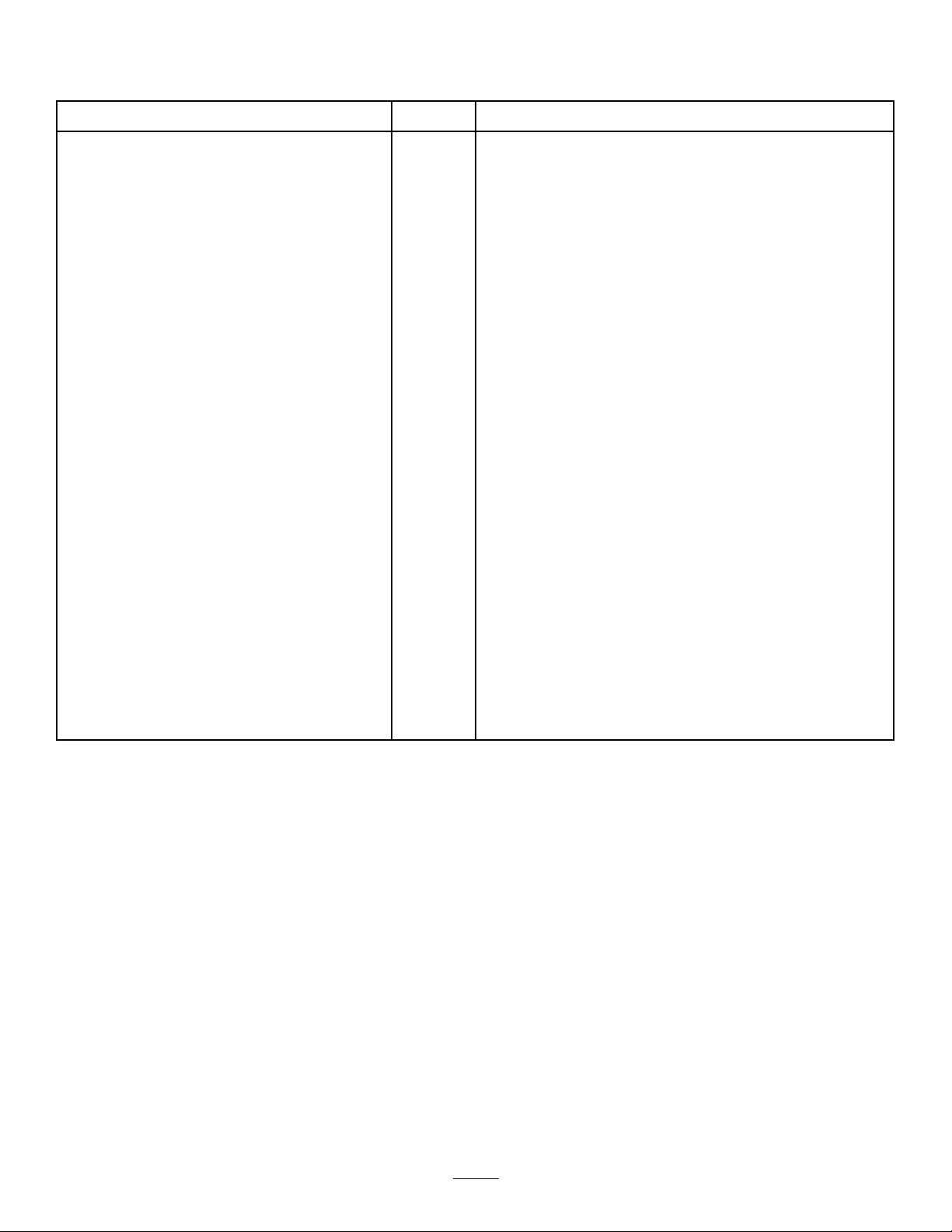
17.Pumpgreaseintothettingsuntilgreaseis
purgedontothegroomershaft.Wipeexcess
greasefromthesealsandshaft.
Note:Lubricatethegroomerbearings(Figure
17andFigure16)weeklyorafterevery10
operatinghours,beforeextendedperiodsof
non-useandimmediatelyaftereverywashing.
Note:Operatethegroomerfor30seconds
aftergreasing.Disengagethecuttingunitand
wipeexcessgreasefromthesealsandshaft.
g010436
Figure16
G027982
g027982
Figure17
Operation
Introduction
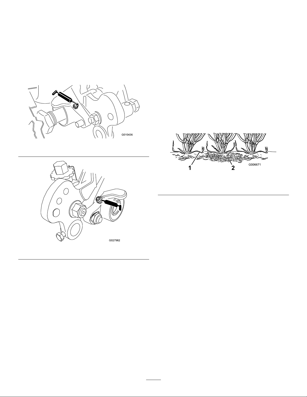
Groomingisperformedintheturfcanopyabovethe
soillevel.Groomingpromotesverticalgrowthofgrass
plants,reducesgrain,andseversstolonsproducing
adenserturf.Groomingproducesamoreuniform
andtighterplayingsurfaceforfasterandtrueraction
ofthegolfball.
Verticuttingisamoreaggressivecultivationtechnique
designedtoremovethatchbycuttingthrough
theturfcanopyandintothethatch/matlayer.
Groomingshouldnotbeconsideredareplacementfor
verticutting.Verticuttingisgenerallyamorerigorous
andperiodictreatmentthatcantemporarilydamage
theplayingsurface,whilegroomingisaroutineand
gentlertreatmentdesignedtomanicuretheturf.
g006671
Figure18
1.Grassrunners(stolons)2.Thatch
Groomingbrushesareamorerecentdevelopment
whicharedesignedtobelessintrusivethan
conventionalgroomingbladeswhenadjustedto
lightlycontacttheturfcanopy.Brushingmaybemore
benecalfortheultra-dwarfcultivars,sincethese
grasstypeshavemoreofauprightgrowthpattern
anddonotllinthatwellthroughhorizontalgrowth.
Brushes,however,caninjureleaftissueiftheyareset
topenetratetoodeeplyintothecanopy.
Groomingissimilartoverticuttinginitsrunnercutting
action.Groomingbladeshowever,shouldnever
penetratethesoillikeverticuttingordethatching.
Groomerbladesarespacedclosertogetherandare
usedmoreoftenthanverticutterssothattheyare
moreeffectiveincuttingrunnersandremovingthatch.
Becausegroominginjuresleaftissuetosomedegree
itshouldbeavoidedduringperiodsofhighstress.
Coolseasonspeciessuchascreepingbentgrass
andannualbluegrassshouldnotbegroomedduring
hightemperature(andhighhumidity)periodsin
midsummer.
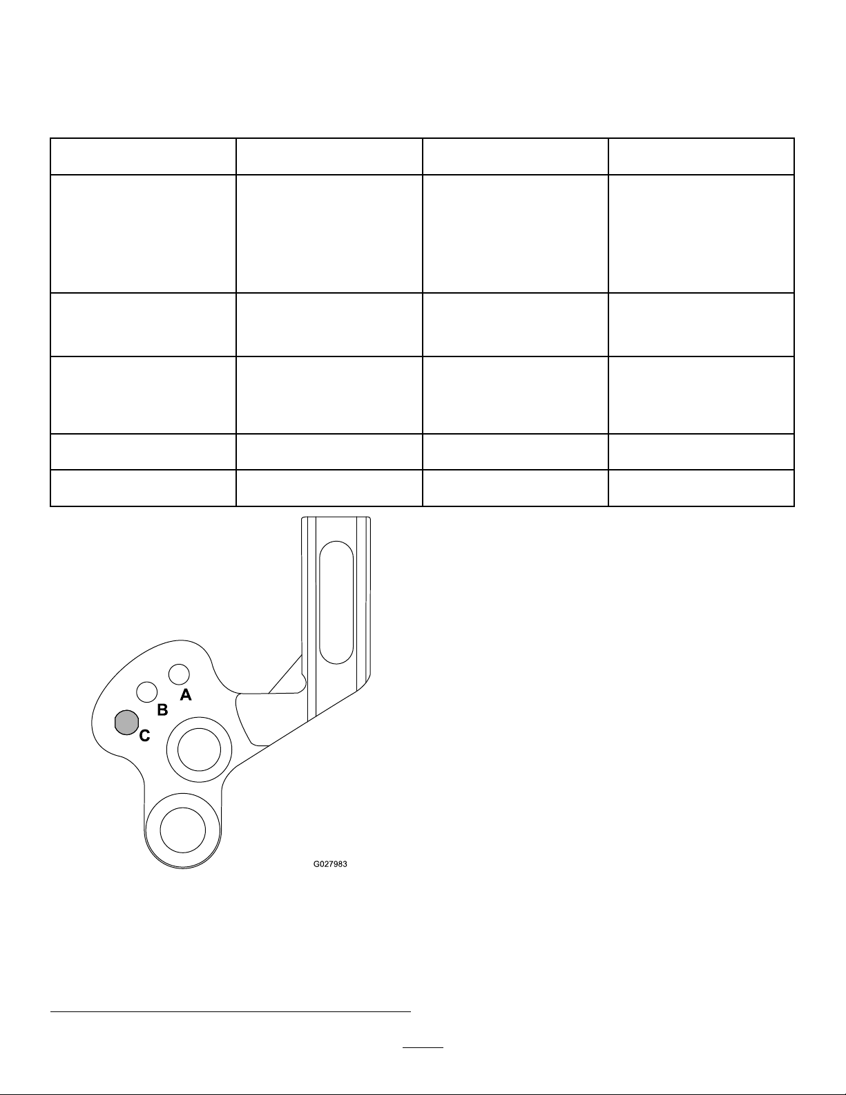
Itisdifculttomakepreciserecommendationsonuse
ofgroomingreelsbecausesomanyvariablesaffect
theperformanceofgrooming,including:
•Thetimeoftheyear(i.e.,thegrowingseason)and
weatherpattern
8

•Thegeneralconditionofeachgreen
•Thefrequencyofgrooming/cutting-bothhowmany
cuttingsperweekandhowmanypassesper
cutting
•Theheight-of-cutsettingonthemainreel
•Theheight/depthsettingonthegroomingreel
•Howlongthegroomingreelhasbeeninuseon
thisgreen
•Thetypeofgrassonthegreen
•Theoverallgreensmanagementprogram(i.e.,
irrigation,fertilizing,spraying,coring,overseeding,
etc.)
•Trafc
•Stressperiods(i.e.,hightemperatures,high
humidity,unusuallyhightrafc)
Thesefactorscanvaryfromgolfcoursetogolfcourse
andfromgreentogreen.Itisimportant,therefore,to
inspectthegreensfrequentlyandvarythegrooming
practiceinaccordancewiththeneed.
Thegroomerissetatthefactorywith13mm(1/2
inch)bladespacing.The13mm(1/2inch)setting
allowsyoutogroomslightlydeepertocutstolons
withoutthinningouttheturfexcessively.Byremoving
spacersandaddingbladesorbyaddingspacersand
removingblades,thegroomercanbechangedto6
mm(1/4inch)or19mm(3/4inch)spacing.
Groomingwith6mm(1/4inch)bladespacingis
recommendedforfastgrowthperiods(springthrough
earlysummer)mainlytothinoutthetoplayerof
thecanopy.Groomingwith19mm(3/4inch)blade
spacingisrecommendedforslowergrowthperiods
(latesummerthroughfallandwinter).Duringhigh
stressperiods,itmaybedesirabletonotusethe
groomingreel.
Note:Groomingwith6mm(1/4inch)bladespacing
tendstoremovemoregrassbladesandthatchand
cutmorerunnersthangroomingwith13mm(1/2
inch)or19mm(3/4inch)bladespacing.Ifyouare
groomingwith6mm(1/4inch)bladespacing,1or2
groomingsperweekwillprobablybesufcientexcept
duringmaximumgrowthperiods.
Note:Thepracticeofchangingthedirectionofcut
eachtimethegreeniscutshouldbecontinuedwhen
agroomerisused.Thisrotationwillenhancethe
effectsofthegrooming.
9

SettingtheHeight/Depthof
theGroomer
Thegroomerbladeheight/depthcanbesetusingthe
followingchart,gures,andprocedure:
Numberofrear-rollerspacers
required
Heightofcut(HOC)Groomer-armpositionHeightofgroomingrange
(HOG)
01.5mm(0.06inch)
3.0mm(0.12inch)
4.8mm(0.19inch)
6.4mm(0.25inch)
A
A
B
B
0.8to1.5mm(0.03to0.06inch)
1.5to3.0mm(0.06to0.12inch)
2.3to4.8mm(0.09to0.19inch)
3.0to6.4mm(0.12to0.25
inch)
17.9mm(0.31inch)
9.7mm(0.38inch)
B
B
3.8to7.9mm(0.15to0.31inch)
4.6to9.7mm(0.18to0.38
inch)
211.2mm(0.44inch)
12.7mm(0.50inch)
B
B
5.3to11.2mm
(0.21to0.44inch)
6.4to12.7mm(0.25to
0.50inch)
315.9mm(0.625inch)B9.4to12.7mm(0.37to0.50
inch)
419.1mm(0.75inch)B12.7to15.7mm(0.50to0.62
inch)
A
B
C
G027983
g027983
Figure19
1.A=Lowheight-of-groom
range
3.C=TransportforBrange
(reducesclearancetothe
grassbasket)
2.B=Highheight-of-groom
range/TransportforA
range
Note:IfyouareusingthegroomeronaneFlex
tractionunit,notethatthegroomercausestheunitto
drainthebatteryfasterthanwithout.Thedeeperyou
setthegroomer,themorepoweritwillrequireandthe
fasterthebatterychargewillbedepleted.
1.Makesurethattherollersareclean.Position
themachineonaat,levelworksurface.
2.Usingtheabovechart,determinetheamountof
rearrollerspacersrequiredtoattainthedesired
groomingheight/depth.
Note:Ifinstalling3or4spacersoneachsideof
therearroller,usethelongerscrews(included
inlooseparts)insteadofthestandardscrews.
3.Settheheightofcutofthemainreel.
4.Usingthechart,determinethepositionrequired
toattainthedesiredgroomingheight/depth.
Raiseorlowerthegroomingreelasfollows:
A.Loosentheboltsontherightandleft
groomerarms(Figure20).
10

G018204
g018204
Figure20
B.RotatethearmsupordowntotheAorB
position(Figure19).
C.Tightentheboltssecuringtheadjustment
(Figure20).
5.On1endofthegroomershaft,measurethe
distancefromthelowesttipofagroomerblade
totheworksurface.
6.Turnthegroomerheightadjustingknob(Figure
21)toraiseorlowerthebladetiptothedesired
groomingheight.
Note:Eachnotchontheadjustingknobis
approximatelyequalto0.08mm(0.003inch)of
groomerdepth.
1
G018185
g018185
Figure21
1.Groomerheight-adjustingknob
7.Repeatthisprocedureontheoppositeendof
thegroomer,thencheckthesettingonrstside.
Adjustasrequired.
8.Ifyouarenotusingthegroomingmode,raise
thegroomingreelfromAtoBorfromBtoC.
Note:Athighergroomingheights,thegrooming
reelmayhavetobesetintheCposition,making
theraise/lowerfeatureunavailable.
TestingthePerformanceof
theGroomer
Important:Improperorover-aggressiveuseof
thegroomingreel(i.e.,toodeeportoofrequent
grooming)maycauseunnecessarystressonthe
turfleadingtoseveregreensdamage.Usethe
groomercautiously.
Itisimportanttodeterminetheperformanceofthe
groomerbeforeputtingitintoregularuseongreens.
Usethefollowingformattestprocedureaspractical
waytodeterminetheproperheight/depthsetting:
1.Setthecuttingreeltotheheightofcutthatyou
wouldnormallyusewithoutagroomingreel.
11

Note:UseaWiehlerollerandscraperforthe
frontroller.
2.Setthegroomerreel1/2oftheheight-of-cut
settingabovetherollerlevel.
Note:Forexample,toseta3.2mm(1/8inch)
height-of-cut,setthegroomerat1.6mm(1/16
inch)abovetheroller.
3.Makeapassoverthetestgreen,thenlower
thegroomerushwiththerollerlevelandmake
anotherpassoverthetestgreen.
4.Comparetheresults.
Note:Therstsetting,whenthesettingwas1/2
theheight-of-cutsettingabovetherollerlevel,
shouldhaveremovedsignicantlylessgrass
andthatchthanthesecondsetting.
5.Checkthetestgreen2or3daysaftertherst
groomingforgeneralconditionordamage.Ifthe
groomedareasareturningyelloworbrown,and
thenon-groomedareasaregreen,thegrooming
wastooaggressive.
Note:Thecolorofthegrasschangeswhen
youusethegroomingreel.Anexperienced
greenssuperintendentcanjudgebythecolor
oftheturf(alongwithcloseexamination)ifthe
currentgroomingpracticeisappropriateforthe
particulargreen.Becausethegroomreelstands
upmoregrassandremovesthatch,thequality
ofcutisnotthesameaswithoutthegroomer.
Thiseffectismostnoticeabletherstfewtimes
youuseagroomeronagreen.
Note:Onmultiplepasses(i.e.,doubleand
triplecutting),thegroomerpenetratesdeeper
oneachsuccessivepass.Multiplepassesare
notrecommended.
6.Aftertestingtheperformanceofthegroomeron
atestgreenandyouobtainsatisfactoryresults,
youcanbegingroomingontheplayinggreens.
However,eachgreenmayresponddifferently
togrooming.Inaddition,growingconditions
constantlychange.Inspectthegroomed
greensfrequentlyandmakeadjustmentstothe
groomingprocedureasoftenasnecessary.
TransportingtheMachine
Whenyouwishtomowwithoutthegroomerorneed
totransportthemachine,raisethegroomingreelinto
itsraisedtransportpositionasshowninFigure19.
Maintenance
CleaningtheGrooming
Reel
Washoffthegroomingreelafteruse.Donotleavethe
groomingreelinwaterorthecomponentswillrust.
GreasingtheGroomer
Bearings
Lubricatethegroomerbearings(Figure22andFigure
23)weeklyorafterevery10operatinghours,before
extendedperiodsofnonuse,andimmediatelyafter
everywashing.Pumpgreaseintottingsuntilgrease
ispurgedontogroomershaft.Wipeexcessgrease
fromthesealsandshaft.
Note:Operategroomerfor30secondsafter
greasing.Disengagecuttingunitandwipeexcess
greasefromthesealsandshaft.
G027982
g027982
Figure22
g010436
Figure23
12

GreasingtheGroomer
Gears
ServiceInterval:Yearly
1.Removethegearboxcoverfromthegroomer
housing,ensuringthatthegroomergearclutch
isengagedtoremovespringforceintothecover
(Figure24).
G018184
1
2
3
g018184
Figure24
1.Bolt3.Gasket
2.Gearboxcover
2.Cleanoutanyexcessgreasefromaroundthe
coverandgears.Donotuseliquidorspray
cleanerstopreventcontaminationofthegrease
orcompatibilityissueswiththeseal.
3.Packthegearsin0.15L(5oz)ofMobilXHP
221orequivalentgrease.
4.Checkfortearsinthegasketandreplaceitif
anyarefound.Cleanthegasketsealingarea
wheninstallingthegaskettoensuresufcient
sealingofthegearcase.
5.Replacethegearboxcover.T orquetheboltsto
11N·m(100in-lb).
InspectingtheBlades
Inspectthegrooming-reelbladesfrequentlyfor
damageandwear.Straightenbentbladeswitha
pliers.Replacewornblades,andtorquethelocknuts
to42to49N·m(31to36ft-lb).Wheninspectingthe
blades,checktoseethattherightandleftbladeshaft
endnutsaretight.
Note:Ifusingspringsteelblades,whenonesideof
thebladesbecomeworn,removethegroomingreel,
rotateit180degrees,andinstallitsothattheunworn
sideisfacingthedirectionofrotation.
Note:Becausethegroomermayintroducemore
debris(i.e.,dirtandsand)intothecuttingunitthan
whatthereelwouldnormallybeexposedto,the
bedknifeandmainreelshouldbecheckedforwear
morefrequently.Thisisespeciallyimportantinsandy
soiland/orwhenthegroomerissetforpenetration.
g010613
Figure25
1.Groomingblade3.Sharpedges
2.Dull(rounded)edges
13

ReplacingtheGrooming
Reel
Youcanremovethegroomingreeltoreplace
individualbladesortheentireshaft.Removeand
replacethegroomingreelshaftusingthefollowing
procedure:
1.Removethegearboxcoverfromthegroomer
housing(Figure26).
G018184
1
2
3
g018184
Figure26
1.Bolt
2.Gearboxcover
3.Gasket
2.Loosentheboltsecuringtherollershafttothe
height-of-cutarm(Figure27).
g030197
Figure27
1.Roller2.Roller-shaftbolt
3.RemovethelocknutandBellevillewasher
securingtheheight-of-cutarmassemblyrodend
tothegroomerdriveassembly(Figure28).
g010439
Figure28
1.Rodendofheightofcut
assembly
3.Locknut
2.Bellevillewasher
4.Removetheplowbolt,nut,andwashersecuring
theheight-of-cutarmassemblytothesideplate
(Figure29).
1
2
G018182
g018182
Figure29
1.Adjuster-armassembly2.Washerandheight-of-cut
nut
14

5.Removetheangelocknutsecuringthedriven
geartotheendofthegroomershaft(Figure30).
Removethegear.
1
23
5
G018183
4
g018183
Figure30
1.Drivegear4.Groomershaft
2.Drivengearlocknut5.Idlergears
3.Drivengear
6.Removethegroomerdrivegearfromthereel
shaft(Figure30).
7.Removethe4screwssecuringthegroomer
driveassemblytotherearmountingplate
(Figure31).
G018940
1
2
g018940
Figure31
1.Groomerdriveassembly2.Screw
8.Removethegroomershaft.
9.Torquethegroomerdrivegearto170N·m(125
ft-lb).
Note:Theuseofanimpactgunisnotenough
toensureproperinstallation.Failingtoproperly
torquethedrivepulleycanresultintheassembly
unscrewingitselfduringoperation.
15

DeclarationofIncorporation
TheT oroCompany,8111LyndaleAve.South,Bloomington,MN,USAdeclaresthatthefollowingunit(s)
conform(s)tothedirectiveslisted,wheninstalledinaccordancewiththeaccompanyinginstructionsontocertain
ToromodelsasindicatedontherelevantDeclarationsofConformity.
ModelNo.SerialNo.ProductDescriptionInvoiceDescriptionGeneralDescriptionDirective
04260—
Counter-RotatingGroomer
DriveSystem,DPACutting
UnitsforGreensmaster
TractionUnit
FLEXGROOMERDRIVE,
COUNTERROTATINGGroomerDriveSystem(CR)2006/42/EC
RelevanttechnicaldocumentationhasbeencompiledasrequiredperPartBofAnnexVIIof2006/42/EC.
Wewillundertaketotransmit,inresponsetorequestsbynationalauthorities,relevantinformationonthispartly
completedmachinery.Themethodoftransmissionshallbeelectronictransmittal.
ThismachineryshallnotbeputintoserviceuntilincorporatedintoapprovedToromodelsasindicatedonthe
associatedDeclarationofConformityandinaccordancewithallinstructions,wherebyitcanbedeclaredin
conformitywithallrelevantDirectives.
Certied:AuthorizedRepresentative:
MarcelDutrieux
ManagerEuropeanProductIntegrity
ToroEuropeNV
Nijverheidsstraat5
2260Oevel
Belgium
JohnHeckel
Sr.EngineeringManagerTel.+3216386659
8111LyndaleAve.South
Bloomington,MN55420,USA
May9,2017
Table of contents
Other Toro Lawn Mower Accessories manuals

Toro
Toro 78514 User manual

Toro
Toro Maxi Sneaker 370 User manual

Toro
Toro 140-5036 User manual

Toro
Toro 78555 User manual

Toro
Toro E-Z Vac 79346 User manual

Toro
Toro 120-7750 User manual

Toro
Toro Flex-Force Power System 51810T User manual

Toro
Toro 147-0520 User manual

Toro
Toro TransPro 80 series User manual

Toro
Toro Groundsmaster 31511 User manual

Toro
Toro 30240 User manual

Toro
Toro GrandStand 133-1495 User manual

Toro
Toro 02858 User manual

Toro
Toro Sand Pro 5040 User manual

Toro
Toro Recycler 126-8701 User manual

Toro
Toro 31353 User manual

Toro
Toro 22232 User manual

Toro
Toro 59225 User manual

Toro
Toro TimeCutter 136-7493 User manual

Toro
Toro 03626 User manual