manuals.online logo
Brands
  1. Home
  2. •
  3. Brands
  4. •
  5. BFT
  6. •
  7. Gate Opener
  8. •
  9. BFT LUX FC User manual

BFT LUX FC User manual

LUX FC - 1
D811189
25-06-98
Ver. prov.01
I
GB
F
D
E
AUTOMAZIONI A PISTONE PER CANCELLI A BATTENTE
PISTON AUTOMATIONS FOR SWING GATES
AUTOMATIONS A PISTON POUR PORTAILS BATTANTS
KOLBEN AUTOMATIONEN FUER FLUEGELGITTERTORE
AUTOMATIZACIONES A PISTON PARA PORTONES CON BATIENTE
LUX FC
ISTRUZIONI
INSTRUCTIONS
INSTRUCTIONS
MONTAGEANLEITUNG
INSTRUCCIONES
www.BFTGateOpeners.com | (800) 878-7829
2 - LUX FC
1) GENERALITA'
Versione LUX 2B ideale per cancelli senza fermo darresto centrale (per zone innevate o quando il cancello è molto alto dal suolo). Un particolare sistema
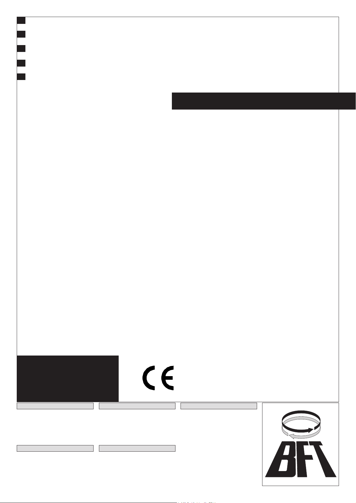
di molle interne, permette di mantenere il cancello bloccato in chiusura anche senza battuta darresto. Il sistema a molle (fig.1), evita allo stelo di andare
a finecorsa e mantiene lelasticità sufficiente a compensare la dilatazione dellolio dovuta agli sbalzi di temperatura climatici. In zone ventose, il blocco
in apertura, mantiene il cancello aperto. Se il cancello rimane aperto per tempi brevi (Max. TCA), si possono evitare i fermi d'arresto in apertura. In caso
contrario, consigliamo di adottore i fermi d'arresto in apertura.
1) GENERAL OUTLINE
LUX 2B is ideal for gates that do not have a central gate stop (for areas prone to snowfalls or when the gate is high above the ground). A special inner
spring-system (fig.1) keeps the gate locked in closed position even when there is no gate stop. The spring system prevents the rod from reaching the
end of its stroke and provides elasticity to compensate for the expansion of the oil caused by sudden changes in the outdoor te mperature. In windy places,
the open position lock keeps the gate open. If the gate only stays open for short amounts of time, opening gate stops do not need to be used. In all differente
condition, ex. the gate stays open for longer periods of time (Max. TCA), we recommend the use of gate stops for the open position.
1) GENERALITES
Version LUX 2B, idéale pour des portails sans butée darrêt central (pour des zones enneigées ou si le portail est placé très en haut par rapport au sol).
Un système spécial de ressorts internes (fig.1) permet de maintenir le portail bloqué en fermeture même sans butée darrêt. Le système à ressorts évite
à la tige daller à la fin de course et maintient lélasticité suffisante à compenser la dilatation de lhuile due aux écarts de température. Dans des régions
venteuses, le butée en ouverture maintient le portail ouvert. Si le portail reste ouvert pour de courtes périodes (Max. TCA), il est possible déviter les butées
darrêt en ouverture. Dans le cas contraire, nous conseillons dadopter les butées darrêt en ouverture.
1) ALGEMEINES
Version LUX 2B, ideal für Tore ohne Mittelfeststeller (für schneereiche Gebiete oder für Tore, die besonders hoch über dem Boden stehen). Durch ein
besonderes, internes Federsystem kann (Abb.1) das Tor auch ohne Anschlag in Schließposition gehalten werden. Das Federsystem hindert den Schaft
daran, den Endanschlag zu erreichen, und behält eine ausreichende Elastizität zum Ausgleich der Ölausdehnung durch klimatische
Temperaturschwankungen bei. In windigen Gebieten hält die Öffnungssperre das Tor offen. Wenn das Tor nur kurz (Max. TCA) offen bleibt, kann auf
die Feststeller der Öffnungsposition verzichtet werden. Andernfalls empfehlen wir die Feststeller der Öffnungsposition einzusetzen.
1) GENERALIDADES
Versión LUX 2B ideal para cancelas o verjas sin tope central de detención (para zonas nevadas o cuando la verja está muy alta respecto al suelo). Un
sistema especial de muelles en el interior (fig.1) permite mantener la verja bloqueada cuando está cerrada, aun sin tope. El sistema de muelles evita
que la barra vaya hasta el tope del recorrido y mantiene la elasticidad necesaria para compensar la dilatación del aceite debida a los cambios climáticos
que hacen variar la temperatura. En zonas con mucho viento, el bloqueo en apertura, mantiene la verja abierta. Si la verja permanece abierta durante
períodos breves (Max. TCA), se pueden evitar los topes de detención en apertura. Por el contrario, le aconsejamos de adaptar los toper de parada en
apertura.
2) DATI TECNICI
Alimentazione :230V±10% 50/60Hz
Motore :monofase 2800 RPM
Potenza assorbita :280W
Condensatore :6.3µF
Corrente assorbita :1.4 A
Massima pressione :30 BAR
Portata pompa :1.25L/min
Forza di spinta :3000 N
Forza di trazione :2600 N
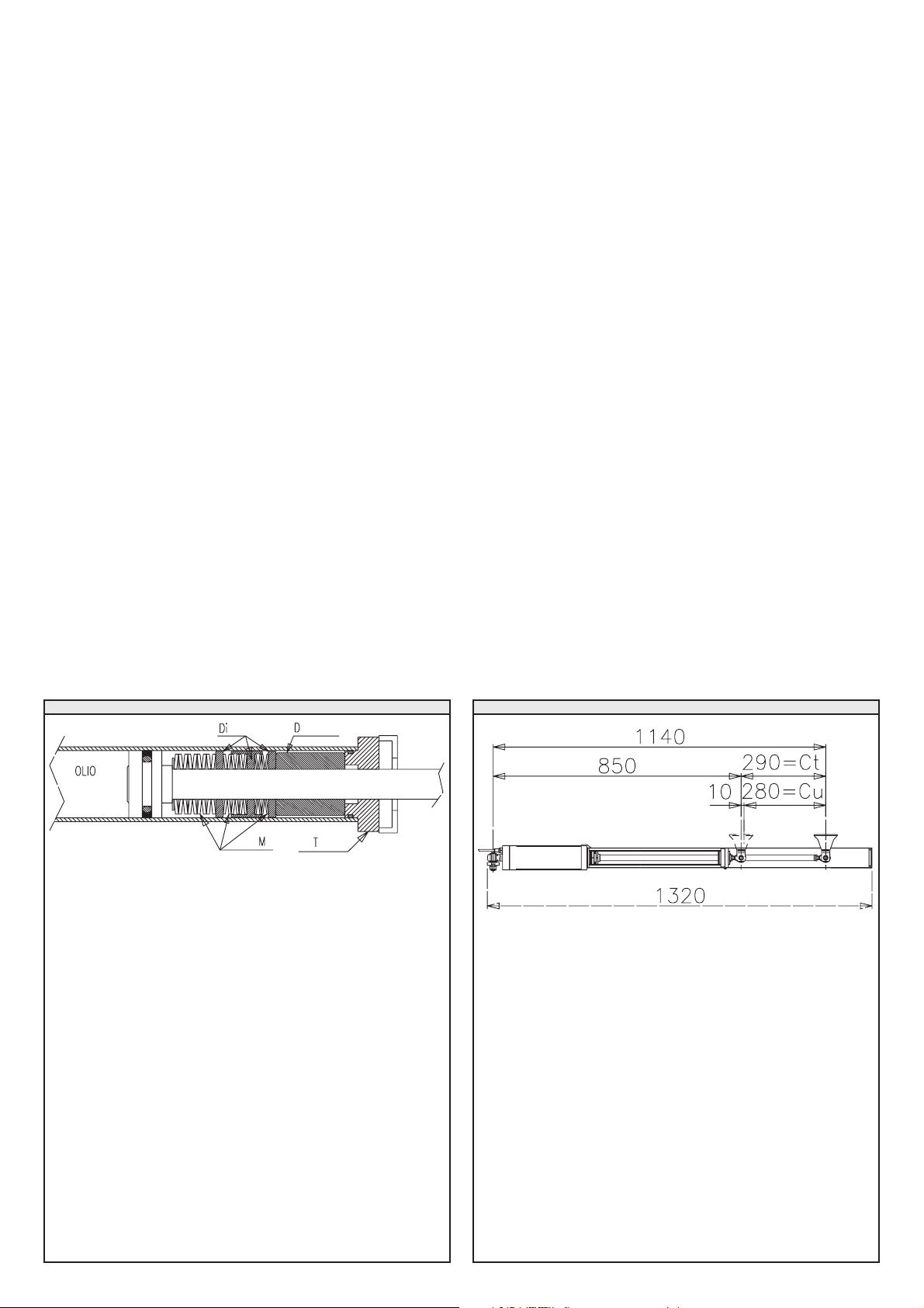
Corsa utile :280mm + compressione molle
Compressione molle :a 100Kg = 280+ 6.25mm
(regolabile con By-pass solo :a 200Kg = 280+ 8.9mm
in chiusura) :a 300Kg = 280+13.4mm
Reazione allurto :Frizione idraulica
Manovra manuale :Chiave di sblocco
Max numero manovre :500 manovre/24h
Protezione termica :160°C
Temperatura ambiente :-10 +60 C°
(scheda SPL per temperature inferiori a 5°C)
Grado di protezione :IP 65
Peso operatore :8.7 Kg
Dimensioni :Vedi fig.2
Olio :IDROLUX
2) TECHNICAL SPECIFICATIONS
Power supply :220V±10% 50Hz
Motor :single-phase, 2800 RPM
Power absorption :280 W
Capacitor :6.3µF
Current absorption :1.4 A
Maximum pressure :20 BAR
Pump delivery :1.25L/min
Pushing force :3000 N
Pulling force :2600 N
Working stroke :280mm + spring compression
Spring compression :with 100Kg = 280+6.25mm
(adjusted using closing :with 200Kg = 280+8.9mm
By-pass valves) :with 300Kg = 280+13.4mm
Impact reaction :Hydraulic clutch
Manual manoeuvre :Release key
Max. no. of manoeuvres :500 Manoeuvres/24h
Thermal protection :130°C
Operation temperature :-10 +60 C°
(SPL board for temperatures less than -10°C)
Protection :IP 65
Controller weight :8.7 Kg
Dimensions :See fig.2
Oil :IDROLUX
2) CARACTÉRISTIQUES TECHNIQUES
Alimentation :230V±10% 50/60Hz
Moteur :monophasé, 2800 tr/min
Puissance absorbée :280 W
Condensateur :6,3µF
Courant absorbé :1,4 A
Pression maximale :30 BAR
Débit de la pompe :1,25l/min
Force de poussée :3000 N
Force de traction :2600 N
Course utile :280mm + compression des ressorts
Compression des ressorts :à 100Kg = 280+6,25mm
(réglable avec soupapes :à 200Kg = 280+8,9mm
de dérivation en fermeture) :à 300Kg = 280+13,4mm
Réaction au choc :Embrayage hydraulique
Manoeuvre manuelle :Clé de déblocage
N° maxi de manoeuvres :500 manoeuvres/24h
Protection thermique :160°C
Température ambiante :-10 +60 C°
(carte SPL pour des températures inférieures à -10°C)
Degré de protection :IP 65
Poids de lopérateur :8,7 Kg
Dimensions :Voir fig.2
Huile :IDROLUX
2) TECHNISCHE DATEN
Stromversorgung :230V±10% 50/60Hz
Motor :einphasig 2800 U/min.
Leistungsaufnahme :280W
Kondensator :6,3µF
Stromaufnahme :1,4A
Höchstdruck :30 bar
Pumpenförderleistung :1,25 l/min
Druckkraft :3000 N
Zugkraft :2600 N
Nutzhub :280 mm + Federspannung
Federspannung :bei 100 kg =280 + 6,25 mm
(über Umgehungsventile :bei 200 kg =280 + 8,9 mm
der Schließung regulierbar) :bei 300 kg =280 + 13,4 mm
Stoßreaktion :Hydraulikkupplung
Bedienung von Hand :Entsperrschlüssel
Max. Öffnungs-und Schließvorgänge :500 Bedienungen/24h
Wärmeschutz :160°C
Außentemperatur :-10 +60°C
(SPL-Karte für Temperaturen unter 5°C)
Schutzkategorie :IP 65
Operatorgewicht :8,7 Kg
Abmessungen :Siehefig.2
Öl :IDROLUX
www.BFTGateOpeners.com | (800) 878-7829
LUX FC - 3
2) DATOS TÉCNICOS
Alimentación :230 V ± 10 % 50/60 Hz
Motor :monofásico 2800 RPM
Potencia consumida :280 W
Condensador :6,3mF
Corriente consumida :1,4 A
Máxima presión :30 Bar
Caudal bomba :1,25 l/min
Fuerza de empuje :3000 N
Fuerza de tracción :2600 N
Recorrido útil :280 mm + compresión muelles
Compresión muelles :a 100 kg = 280 + 6,25 mm
(regulable con válv. By-pass :a 200 kg = 280 + 8,9 mm
en cierre) :a 300 kg = 280 + 13,4 mm
Reacción al choque :Embrague hidráulico
Maniobra manual :Llave de desbloqueo
Número máx. maniobras :500 maniobras/24 h
Protección térmica :160° C
Temperatura ambiente :-10° +60°C
(ficha SPL para temperaturas inferiores a 5°C)
Grado de protección :IP 65
Peso operador mecánico :8,7 kg
Dimensiones :véase fig.2
Aceite :IDROLUX
3) POSITIONING (fig.3)
3) POSITIONNEMENT (fig.3)
3) POSITIONERUNG (fig.3)
3) COLOCACION (fig.3)
Ct =Corsa totale (290mm + compressione molle)
Cu=Corsa utile (280mm + compressione molle)
Ct=290+spring compression (total stroke)
Cu=280+spring compression (working stroke)
Ct=290+compression des ressorts (course total)
Cu=280+compression des ressorts (course utile)
Ct=290+Federspannung (Nutzhublänge)
Cu=280+Federspannung (Nutzhub)
Ct=290 + compresión muelles (recorrido total)
Cu=280 + compresión muelles (recorrido útil)
Di =Distanziali intermedi
D =Distanziale
M =molle a tazza
T =Testata cilindro
Di =Middle spacers
D = spacer
T =Head
M =Belleville washers
Di =Entretoises intermédiaires
D =Entretoise
T =Téte
M =Rondelles belleville
Di =ZWISCHENABSTANDSTÜCKE
D =ABSTANDSTÜCK
T =KOPF
M =TELLERFEDERN
Di =DISTANCIADORES INTERMEDIOS
D =DISTANCIADOR
T =CABEZAL
M =MUELLES CÓNICOS DE COMPRESIÓN
FIG.2FIG.1
www.BFTGateOpeners.com | (800) 878-7829
4 - LUX FC
D =Lunghezza anta MAX 2000mm
a-b =Quote di installazione staffa P
C =1140+Corsa molle ± 6mm di regolazione
Kg =Peso anta MAX 400 Kg
P =Staffa attacco pilastro
F =Forcella attacco anta
a°=Gradi apertura anta
D = Leaf length (2000 mm MAX)
a-b = P bracket installation value
C = 1140+Spring stroke ± 6mm adjustment
Kg = Leaf weight (400 Kg MAX)
P = Gate-post fastening bracket
F = Leaf fastening fork
a°= Degrees of leaf opening
D = Longueur du vantail (2000 mm MAXI)
a-b = Cotes dinstallation de la patte P
C = 1140+Course des ressorts ± 6mm de réglage
Kg = Poids du vantail (400 Kg MAXI)
P = Patte de fixation au poteau
F = Fourche de fixation vantail
a°= Degrés douverture du vantail
D = Torflügellänge max. 2000 mm
a-b = Installationshöhe Stange P
C = 1140 + Federhub ± 6 mm Einstellspiel
kg = Torflügelgewicht max. 400 kg
P = Spanneisen zur Anbringung am Pfosten
F = Gabel zur Torflügelbefestigung
a°= Öffnungsgrad des Torflügels
D = Largo hoja MÁX. 2000 mm
a-b = Cotas de instalación abrazadera P
C = 1140 + Recorrido muelles ± 6 mm de regulación
kg = Peso hoja MÁX. 400 kg
P = Abrazadera enganche pilar
F = Horquilla sujeción hoja
a°= Grados de apertura hoj
a (mm)
110 120 130 140 150
110 112 104 98
120 117 105 99 94
b (mm) 130 107 99 94 90
140 112 100 94 90
150 102 94 90
160 94 89
ATTENZIONE (FIG.4): Prima di iniziare linstallazione, regolare
locchiello dello stelo a 29mm come in figura. Ciò consente una
regolazione in +/- 6mm della lunghezza dello stelo. Ad installazione
ultimata, questa regolazione, consente lallineamento delle ante in
chiusura. Se ciò non è sufficiente, è possibile compensare lallineamen-
to anche tarando accuratamente i by-pass di chiusura.
WARNING (FIG.4): Before starting installation adjust the eye
of the 29 mm rod as shown in the figure. This allows a ± 6mm adjustment
of the rod length. Once installation is complete, this adjustment allows
the leaves to be aligned on closing.
If this adjustment is not sufficient, alignment can also be compensated
by calibrating the closing by-pass valves precisely.
ATTENTION (FIG.4): Avant de commencer linstallation, régler
loeillet de la tige à 29 mm (voir figure). Ceci permettra un réglage en ±
6mm de la longueur de la tige. Une fois linstallation terminée, ce
réglage permettra lalignement des vantaux en fermeture.
Si cela ne suffisait pas, il est possible de compenser lalignement aussi
en réglant soigneusement les soupapes de dérivation de fermeture.
ACHTUNG (FIG.4): Vor Beginn der Installation die Schaftöse
auf 29 mm einstellen, wie in der Abbildung gezeigt. Dadurch wird eine
Einstellung von ± 6 mm der Schaftlänge ermöglicht. Am Ende dieser
Einstellungkönnen dieTorflügel inSchließposition ausgerichtetwerden.
Wenn dies nicht ausreichen sollte, kann die Ausrichtung auch durch
eine sorgfältige Einstellung der Umgehungsventile der Schließung
ausgeglichen werden.
ATENCIÓN (FIG.4): Antes de iniciar la instalación, regular la
argolla de la barra a 29 mm como se muestra en el dibujo. Esto permite
regular el largo de la barra a ± 6 mm. Con la instalación ultimada, dicha
regulación permite el alineamiento de las hojas cuando éstas se
cierran.
Si esto no es suficiente, también se puede compensar el alineamiento,
calibrando cuidadosamente las válvulas by-pass de cierre.
Valore ottimale. Velocità costante.
Ideal values. Constant speed.
Valeurs optimales. Vitesse constante.
Optimale werte. Konstant geschwindigkeit.
Valores óptimos. Velocidad constante.
VALORI IN GRADI
VALUES GIVEN IN DEGREES
VALEURS EXPRIMÉES EN DEGRÉS
WERTE IN GRAD
VALORES EXPRESADOS EN GRA
FIG.3 FIG.4
a°
www.BFTGateOpeners.com | (800) 878-7829

Other BFT Gate Opener manuals

BFT deimos ultra bt a 400 User manual

BFT

BFT deimos ultra bt a 400 User manual

BFT Deimos User manual

BFT

BFT Deimos User manual

BFT PHOBOS N BT User manual

BFT

BFT PHOBOS N BT User manual

BFT KUSTOS BTA User manual

BFT

BFT KUSTOS BTA User manual

BFT FL130 User manual

BFT

BFT FL130 User manual

BFT PHOBOS N BT User manual

BFT

BFT PHOBOS N BT User manual

BFT ECOSOL User manual

BFT

BFT ECOSOL User manual

BFT SUB BT User manual

BFT

BFT SUB BT User manual

BFT ICARO User manual

BFT

BFT ICARO User manual

BFT PHOBOS BT B 25 User manual

BFT

BFT PHOBOS BT B 25 User manual

BFT ORO User manual

BFT

BFT ORO User manual

BFT IGEA BT User manual

BFT

BFT IGEA BT User manual

BFT FCS User manual

BFT

BFT FCS User manual

BFT KIT CAPIENZA D113708 User manual

BFT

BFT KIT CAPIENZA D113708 User manual

BFT ELI-250 User manual

BFT

BFT ELI-250 User manual

BFT ELI-250 User manual

BFT

BFT ELI-250 User manual

BFT STOPPY MBB 219-700.C User manual

BFT

BFT STOPPY MBB 219-700.C User manual

BFT EBP AC A User manual

BFT

BFT EBP AC A User manual

BFT Cell Switch Prime Instruction Manual

BFT

BFT Cell Switch Prime Instruction Manual

BFT LUX User manual

BFT

BFT LUX User manual

BFT CELLULA 180 User manual

BFT

BFT CELLULA 180 User manual

BFT KUSTOS ULTRA BT User manual

BFT

BFT KUSTOS ULTRA BT User manual

BFT ELI250N User manual

BFT

BFT ELI250N User manual

BFT PHOBOS N-PHOBOS N L User manual

BFT

BFT PHOBOS N-PHOBOS N L User manual

Popular Gate Opener manuals by other brands

FAAC Estate Swing E-S 1600 Series instruction manual

FAAC

FAAC Estate Swing E-S 1600 Series instruction manual

CAME FERNI 1024 KIT installation manual

CAME

CAME FERNI 1024 KIT installation manual

DoorKing 1603 Installation & owner's manual

DoorKing

DoorKing 1603 Installation & owner's manual

Allstar Gate Star 6000 Installation and owner's manual

Allstar

Allstar Gate Star 6000 Installation and owner's manual

PPA DZ FORT Technical manual

PPA

PPA DZ FORT Technical manual

Guardian 715BBU owner's manual

Guardian

Guardian 715BBU owner's manual

Proteco Shark New Installation and use manual

Proteco

Proteco Shark New Installation and use manual

Nice Naked Sliding NKSL400 Instructions and warnings for installation and use

Nice

Nice Naked Sliding NKSL400 Instructions and warnings for installation and use

Proteco MEKO installation manual

Proteco

Proteco MEKO installation manual

Ghost Controls DTP1 quick start guide

Ghost Controls

Ghost Controls DTP1 quick start guide

Manaras Opera Opera-GH Installation and instruction manual

Manaras Opera

Manaras Opera Opera-GH Installation and instruction manual

CAME BX Series installation manual

CAME

CAME BX Series installation manual

CAME BKV Series installation manual

CAME

CAME BKV Series installation manual

WORKMASTER GO-A13-HA Operator's guide

WORKMASTER

WORKMASTER GO-A13-HA Operator's guide

Biketronics CribClicker BT385 installation guide

Biketronics

Biketronics CribClicker BT385 installation guide

tau 250T-CONNECT installation guide

tau

tau 250T-CONNECT installation guide

Chamberlain SCS200 Installations

Chamberlain

Chamberlain SCS200 Installations

DoorKing 1601 Series Installation & owner's manual

DoorKing

DoorKing 1601 Series Installation & owner's manual

manuals.online logo
manuals.online logoBrands
  • About & Mission
  • Contact us
  • Privacy Policy
  • Terms and Conditions

Copyright 2025 Manuals.Online. All Rights Reserved.