0-7
OPERATIONAL TIPS
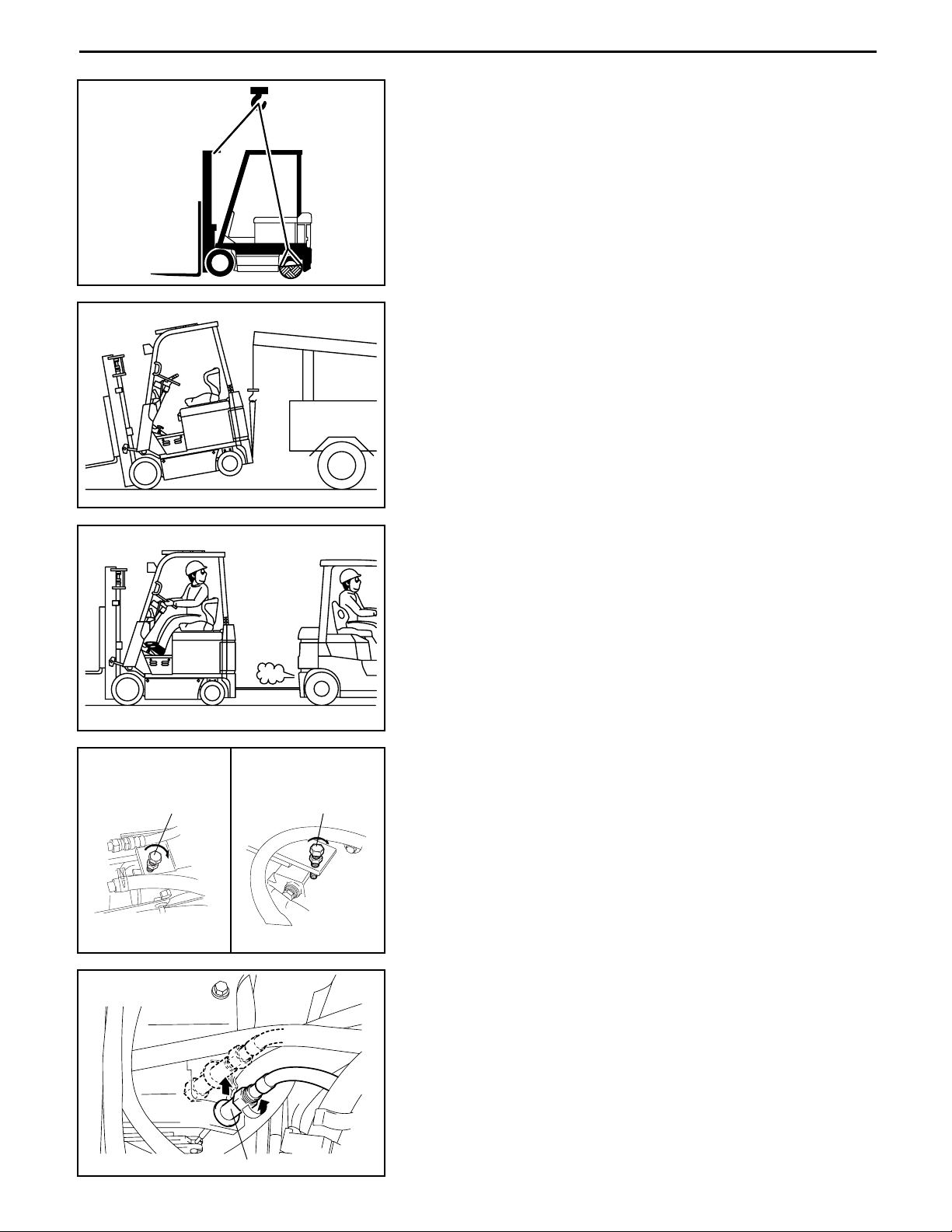
1.Safe operation
(1) Afterjacking up,always support with wooden blocks orrigid stands.
(2) When hoisting the vehicle orits heavy component,use wire rope(s) with a sufficientreserve in load
capacity.
(3) Always disconnectthe battery plug before the inspection orservicing of electricalparts.
2.Tactfuloperation
(1) Prepare the mechanic tools,necessary measuring instruments (circuit tester,megger,oil pressure
gauge,etc.) and SSTs before starting operation.
(2) Before disconnecting wiring,always check the cable colorand wiring state.
(3) When overhauling functionalparts,complicated portions orrelated mechanisms,arrange the parts
neatly to preventconfusion.
(4) When disassembling and inspecting such a precision part as the controlvalve,use clean tools and
operate in a clean location.
(5) Follow the described procedures fordisassembly,inspection and reassembly.
(6) Replace,gaskets,packing and O-rings with new ones each time they are disassembled.
(7) Use genuine Toyota parts forreplacement.
(8) Use specified bolts and nuts.Observe the specified tightening torque atthe time of reassembly.
(Tighten to the centerof the specified tightening torque range.)
If no tightening torque is specified,tighten the bolt ornutaccording to the standard tightening
torque table.
3.Protection of functionalparts
(1) Thoroughly check each connectorforany failure in orimperfectconnection before reconnecting the
battery plug afterthe end of vehicle inspection ormaintenance.
Failure in or imperfect connection ofconnectors related to controllers, especially, may
damage elements inside the controllers.
4.Confirming defectstatus
Do notstart immediate disassembly orreplacement,butfirstconfirm if such disassembly or
replacementis actually needed.
5.Handling of waste fluid,etc.
When draining waste fluid from the vehicle,always receive it with an appropriate container.
Since careless orarbitrary discharge ordisposalof oil,fuel,coolant,oil filter,battery orany other
harmfulsubstance may cause adverse affectto people orenvironmentaldestruction,sort each waste
and always ask an authorized contractorforappropriate disposal.
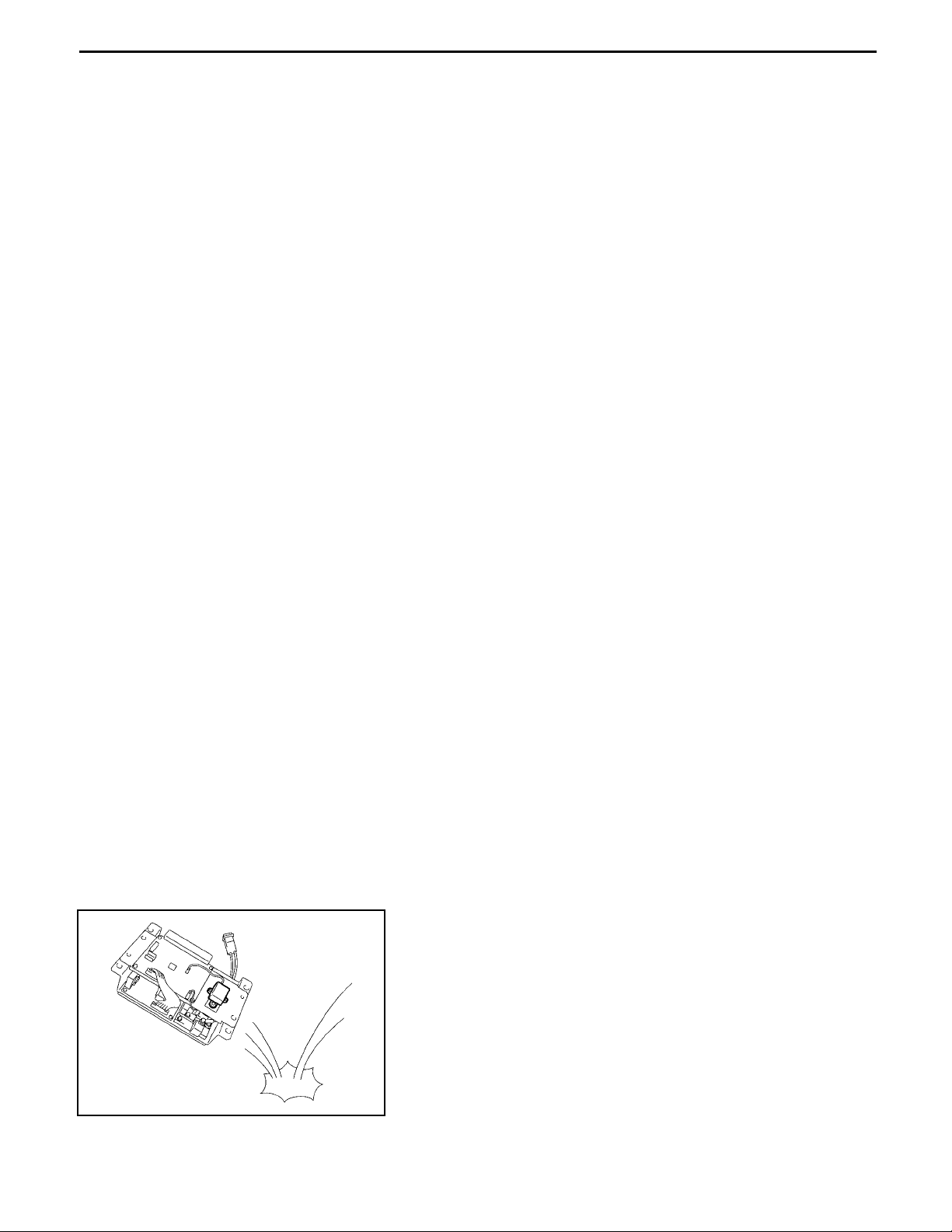
6.Handling of electronic parts
(1) Neverapply impacts to electronic parts such as a
microcomputerorrelay.
(2) Neverletelectronic parts be exposed to a high
temperature orhumidity.
(3) Do nottouch connectorpins since they may be
deformed orbe damaged due to static electricity.