SPECIFICATIONS
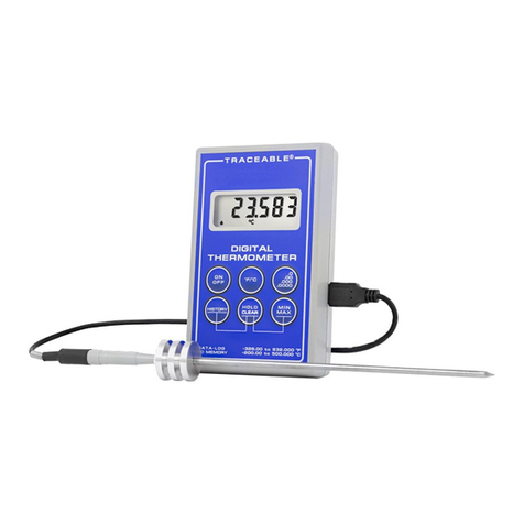
Range: –100.00 to 199.99°C (6410)
–100.00 to 70.00°C (6411)
Update Rate: 1 second
Battery: 2 each AAA (1.5V)
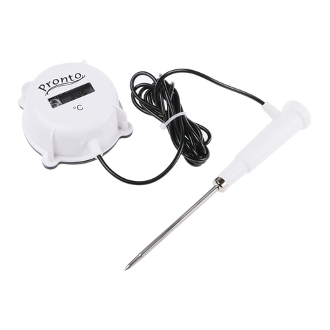
Probe: Waterproof, platinum RTD stainless-steel
probe, 0.13" dia.; stem: 9"; overall: 12",
10-foot PVC cable
SETTING THE TIME-OF-DAY/DATE
Slide the DISPLAY switch to the DATE/TIME position, the
display will show the time-of-day and date.
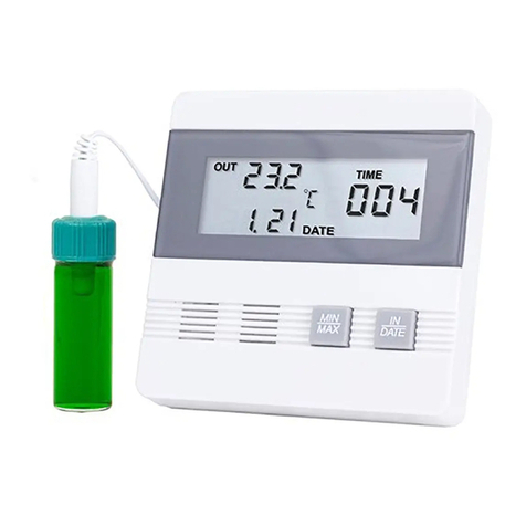
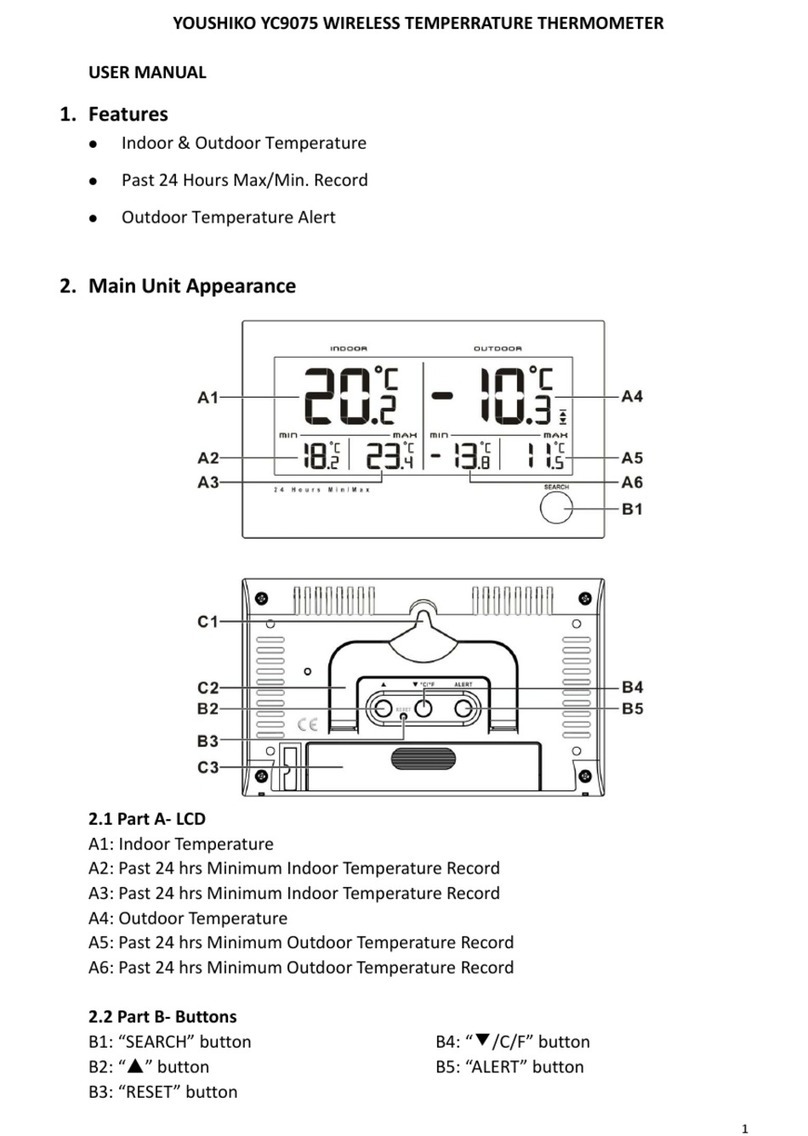
Place your thumb on the middle of the front of the unit and slide
the top cover down to expose the controls (see image above).
While in the time-of-day/date display, pressing the SELECT
button or ADVANCE button will allow the date and time to be
set. Pressing the SELECT button will cause the digits to ash
in the following order Year→Month→Day→Hours→ Minutes
→12/24 hour time→No digits ashing (value set). Once the
desired item is ashing, pressing the ADVANCE button will
increment the value. Press and hold the ADVANCE button for
<3 seconds for continuous incrementation.
With the desired time-of-day/date appearing on the display,
press the SELECT button until no digits are ashing on the
display. The time-of-day/date will be saved.
While in the time-of-day/date display, pressing the EVENT
DATE/TIME button will switch the date display between Month/
Day (M/D) and Day/Month (D/M) display modes.
Note: While in the time-of-day/date setting mode, if no button
is pressed for fteen (15) seconds, the unit automatically exits
from the setting mode. All digits will stop ashing to indicate
setting mode has been exited.
VIEWING THE TIME-OF-DAY/DATE
To view the time-of-day/date, slide the DISPLAY switch to the
DATE/TIME position.
DISPLAYING °F OR °C
To display the temperature readings in Fahrenheit or Celsius,
slide the °C/°F switch to the desired position.
MINIMUM AND MAXIMUM MEMORY
The minimum temperature recorded into memory is the
minimum temperature achieved since the last time the
memory was cleared. The maximum temperature recorded
into memory is the maximum temperature achieved since the
last time the memory was cleared.
Minimum and maximum temperature memories are NOT
programmable (see HI/LO ALARMS).
Below are the FOUR different memory features:
• MIN/MAX: Minimum (MIN) and maximum (MAX) tempera-
ture achieved with time-of-day and date occurred since
the last time the memory was cleared.
–AND–
• 24-HOUR: Minimum (MIN) and maximum (MAX) tempera-
ture achieved for each hour within a 24-hour period.
• 7-DAY: Minimum (MIN) and maximum (MAX) temperature
achieved for each day within a 7-day period.
–OR–
• 31-DAY: Minimum (MIN) and maximum (MAX) tempera-
ture achieved each day during a 31-day period and the
time-of-day it occurred.
TO TOGGLE BETWEEN 31-DAY AND 24-HOUR/7-DAY
MEMORY MONITORING MODES
1. Slide the ‘DISPLAY’ switch to the MIN/MAX position.
2. Slide the ‘HISTORY” switch to the ON position.
3. Press the ‘EVENT DATE/TIME’ button 3 times. The LCD
will display the current history mode.
4. To toggle to the other mode press the ‘SELECT’ button.
The LCD will change the display to the new history mode.
TO VIEW THE MINIMUM/MAXIMUM MEMORY
1. Slide the DISPLAY switch to the ‘MIN/MAX’ position.
2. Press the ‘EVENT DATE/TIME’ once to view the minimum
temperature achieved during the most recent monitoring
period and the time/date it occurred.
3. The next press of the ‘EVENT DATE/TIME’ button will dis-
play the maximum temperature achieved during the most
recent monitoring period and the time/date it occurred.
4. Holding the ‘EVENT DATE/TIME’ button continuously for
2 seconds or no button press for 15 seconds will return
the display to the default min/max screen.
CLEARING THE MINIMUM/MAXIMUM MEMORY
1. Slide the ‘DISPLAY’ switch to the MIN/MAX position.
The display will show the current temperature and mini-
mum/maximum memory.
2. Press the ‘CLEAR MIN/MAX’ button to clear the minimum
and maximum memories.
TO VIEW 24-HOUR MIN/MAX MEMORY (24-hour le)
1. Slide the ‘DISPLAY’ switch to the ‘MIN/MAX’ position.
2. Slide the ‘HISTORY’ switch to the ‘ON’ position.
3. Slide the ‘PERIOD’ switch to the ‘HR’.
4. Press the ‘EVENT DATE/TIME’ button three times to
begin viewing the hourly data. The LCD will display the
current history viewing mode.
5. The next press of the ‘EVENT DATE/TIME’ button will
display the minimum temperature achieved during the
current hour.
6. Press the ‘EVENT DATE/TIME’ button again to view the
maximum temperature achieved during the current hour.
7. Each subsequent press of the ‘EVENT DATE/TIME’
button will display an hourly minimum or maximum
temperature reading for the previous hourly periods in
descending chronological order.
8. Once all saved readings have been viewed, the display
will return to the default min/max screen.
9. Holding the ‘EVENT DATE/TIME’ button continuously for
2 seconds or no button press for 15 seconds will return
the display to the default min/max screen.
NOTE: All data for the 24-hour le will be lost when the mem-
ory is toggled to the 31-day le. Also, all data for the 7-day
le will be lost when the memory is toggled to the 31-day le.
CLEARING THE 24-HOUR MINIMUM/MAXIMUM MEMORY
1. Slide the ‘DISPLAY’ switch to the MIN/MAX position.
The display will show the current temperature and mini-
mum/maximum memory.
2. Slide the ‘PERIOD’ switch to ‘HR’.
3. Press the ‘EVENT DATE/TIME’ button three times to view
the memory data.
4. Press ‘CLEAR MIN/MAX’ to clear the memory data. Note:
Clearing the 24-hour MIN/MAX will NOT clear the 7-day
MIN/MAX.
TO VIEW 7-DAY MIN/MAX MEMORY (7-day le)
1. Slide the ‘DISPLAY’ switch to the ‘MIN/MAX’ position.
2. Slide the ‘HISTORY’ switch to the ‘ON’ position.
3. Slide the ‘PERIOD’ switch to the ‘DAY’.
4. Press the ‘EVENT DATE/TIME’ button three times to
begin viewing the daily data. The LCD will display the
current history viewing mode.
5. The next press of the ‘EVENT DATE/TIME’ button will
display the minimum temperature achieved during the
current day.
6. Press the ‘EVENT DATE/TIME’ button again to view the
maximum temperature achieved during the current day.
7. Each subsequent press of the ‘EVENT DATE/TIME’ but-
ton will display a daily minimum or maximum temperature
reading for the previous 7-day period in descending
chronological order.
8. Once all saved readings have been viewed, the display
will return to the default min/max screen.
9. Holding the ‘EVENT DATE/TIME’ button continuously for
2 seconds or no button press for 15 seconds will return
the display to the default min/max screen.
CLEARING THE 7-DAY MINIMUM/MAXIMUM MEMORY
1. Slide the ‘DISPLAY’ switch to the MIN/MAX position.
The display will show the current temperature and mini-
mum/maximum memory.
2. Slide the ‘PERIOD’ switch to ‘DAY’.
3. Press the ‘EVENT DATE/TIME’ button three times to view
the memory data.
4. Press ‘CLEAR MIN/MAX’ to clear the memory data.
Note: Clearing the 7-daily MIN/MAX will NOT clear the
24-hour MIN/MAX.
TO VIEW 31-DAY MIN/MAX MEMORY (31-day le)
1. Slide ‘DISPLAY’ switch to the ‘MIN/MAX’ position.
2. Slide the ‘HISTORY’ switch to the ‘ON’ position.
3. Press the ‘EVENT DATE/TIME’ button 3 times. The LCD
will display the current memory mode.
4. The next press of the ‘EVENT DATE/TIME’ button will
display the minimum temperature achieved during the
current day.
5. Press the ‘EVENT DATE/TIME’ button again to view the
maximum temperature achieved during the current day.
6. Each subsequent press of the ‘EVENT DATE/TIME’ but-
ton will display a daily minimum or maximum temperature
reading for the previous 31-day period in descending
chronological order.
7. Once all saved readings have been viewed, the display
will return to the default min/max screen.
8. Holding the ‘EVENT DATE/TIME’ button continuously for
2 seconds or no button press for 15 seconds will return
the display to the default min/max screen.
CLEARING THE 31-DAY MINIMUM/MAXIMUM MEMORY
1. Slide the ‘DISPLAY’ switch to the MIN/MAX position.
The display will show the current temperature and mini-
mum/maximum memory.
2. Press the ‘EVENT DATE/TIME’ button three times to view
the 31-day memory.
3. Press ‘CLEAR MIN/MAX’ to clear the memory data.
HI/LO ALARMS
Alarm limits may be set in 0.1° increments.
With the alarm switch set to the ON position:
- The unit will sound an alarm and ash the LEDs when
the temperature measured is outside the alarm limits that
have been set (equal to or lower than the low alarm set
point, or equal to or greater than the high alarm set point).
- The alarm will sound regardless of the display mode.
SETTING THE TEMPERATURE ALARM LIMITS
1. Slide the DISPLAY switch to the ALARM position.
The display will show the current temperature and low/
high alarm set points.
2. While in the alarm display mode, pressing the ‘SELECT’
button will allow the alarm limits to be set.
Pressing the SELECT button will cause the digits to ash in
the following order: Low Alarm 1st Digits→Low
Alarm 2nd Digit→Low Alarm Decimal Digit→ High Alarm
1st Digits→High Alarm 2nd Digit→High Alarm Decimal
Digit→No digits ashing (value set).
3. Once the desired item is ashing, pressing the ADVANCE
button will increment the value.
4. With the desired alarm set points appearing on the dis-
play, press the SELECT button until no digits are ashing
on the display. The alarm settings will be saved.


