Page 10
TEF 2880 NAVIGATION LIGHT - INSTALLATION AND USER MANUAL
Timer
The light has a timer built in to monitor working hours,
pre-set to 100,000 hours. When 100,000 working hours
has elapsed, the light stops working and hence alarm
will arise at navigation ligths control system.
1. Part # 2880***X* where X = 0 or 9. (Versions without
digital input/output):
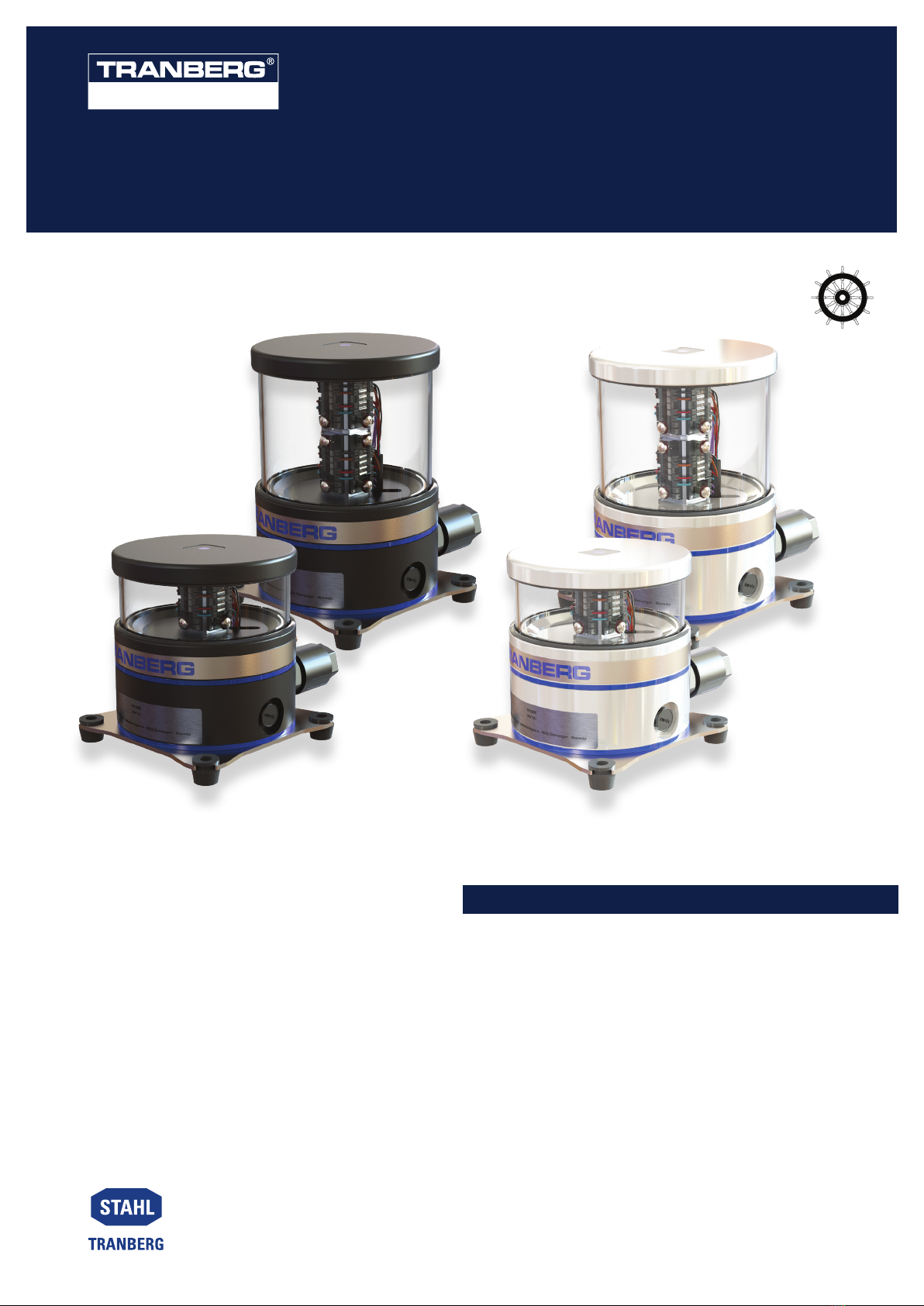
2. Part # 2880***1* (Versions with digital input/output,
on/off (blinking) control):
º Digital input = on/off or blinking control. Logical
‘0’ = off. ‘1’ = on. Alternatively, tie DI to +24V
and control on/off by switching power. Do not
use this mode for blinking lights.
º Digital output = Alarm output, normal state =
‘high’.
In addition, two special control modes are available:
3. Panama steering lights. Part # 28805513* (Panama
steering light):
º On/off control by switching power on and off.
º Digital input = step dimming control. 7
dimming steps. Shifts one dimming step for
each positive pulse at DI.
º Digital output = Alarm output, normal state =
‘high’.
CONTROL AND MONITORING
Control and monitoring
Navigation lights and signal light required by national
and canal authorities shall be connected to a dedicated
control and monitoring system. Control and monitoring
of the TEF2880 series can be obtained in two different
ways (ref. part # matrix page 4):
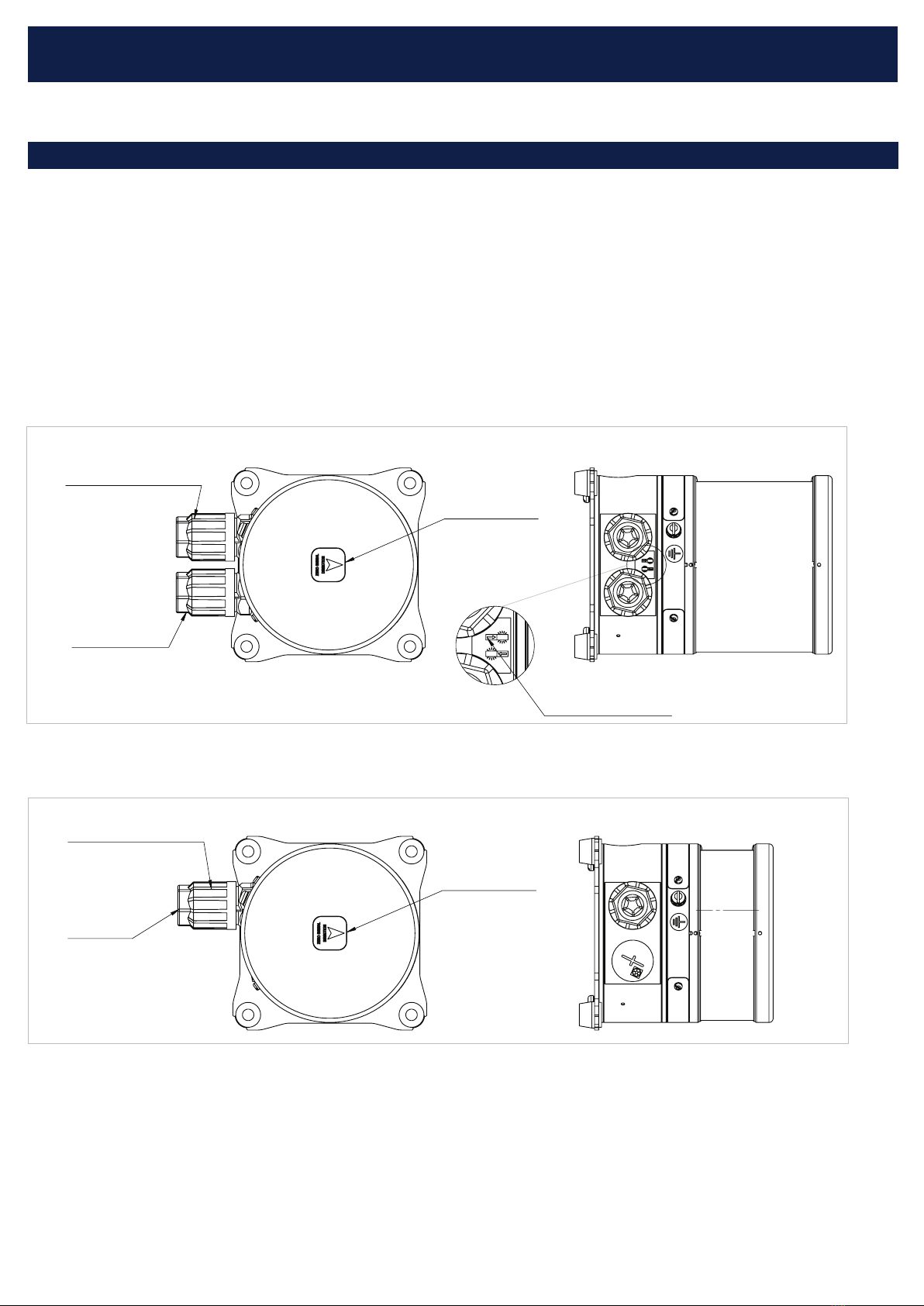
1. Part # 2880***X* where X = 0 or 9. (Versions without
digital input/output):
º On/off control by switching power on and off.
º Monitoring by measuring current. When a
failure occurs, current draw falls below 10 mA.
The monitoring system must be compatible
with table below.
Power * Current
draw *
Current
draw
@ lamp
failure
5 nm lights Max. 15 W Min. 240 mA
3 nm lights Max. 8 W Min. 80 mA
2 nm lights Max. 5 W Min. 50 mA
Additional fishing
lights Max. 3 W Min. 15 mA
* Note: Varies with supply voltage, colour, temperature and
LED production batch.
Maintenance
No maintenance required.
For cleaning, use only mild detergents. Alcohol and petro-
leum based products may damage the light.
MAINTENANCE
DISPOSAL
4. Self-contained blinking lights. Part # 2880***X*
where X = 5, 6, 7 or 8.
º On/off control by switching power on and off.
º D Digital output = Alarm output, normal state
= ‘high’.
The navigation light monitors the following parameters,
and if a failure occurs the light is switched off resulting
in current draw <10mA. (Alarm output switch state for
versions with DI/DO).
º Failure of any LED.
º Deviating LED current.
º Abnormal temperature.
º Under-voltage.
º Working hours >100,000 hours.
Disposal
The TEF2880 shall be disposed of according to national
regulations. The equipment may be returned to the manu-
facturer for recycling, shipment is the customer’s respon-
sibility.